Abstract
Steel truss stiffening girders are widely used when designing long-span bridges in mountainous areas owing to their distinct characteristics compared to the streamlined box girder. However, natural wind in mountainous areas is very complex with high turbulence and large attack angles which adversely affect the flutter performance of long-span bridges with truss girders. Aerodynamic countermeasures are widely adopted to improve flutter performance. This paper studies the flutter performance and the effects of various aerodynamic countermeasures on the flutter improvement of a 1060 m truss-stiffened girder suspension bridge spanning mountainous canyon by wind tunnel tests of the sectional model and full-bridge model. First, sectional model tests with the original girder section were carried out under various wind attack angles. Subsequently, to improve the flutter stability of the bridge under the most unfavorable wind attack angle, several aerodynamic countermeasures including central upper stabilizer, horizontal stabilizer, combined central upper and horizontal stabilizers, and sealed central traffic barrier were proposed and sectional model tests with optimized girders were conducted. The results show that the aerodynamic mitigation effect of the central upper stabilizer, horizontal stabilizer, as well as combined measure, is closely related to the geometric dimension of the stabilizing plate. It is found that large geometric dimensions effectively increase the flutter critical wind speed of the truss girder. Considering sealed central traffic barrier measure, the smaller ventilation rates result in larger flutter critical wind speed of the girder. The sealed central traffic barrier measure with a 50 % ventilation rate is deemed as the most optimal aerodynamic countermeasure in consideration of aesthetics, economy, and safety. Finally, the effectiveness of optimal countermeasure is validated through an aeroelastic full-bridge model test. The research is conducted to provide references on flutter performance optimization of similar bridges in the future.
Highlights
- Studying and optimizing the flutter performance of a long-span bridge by employing the aerodynamic countermeasures via wind tunnel tests
- Large geometric dimensions of the stabilizing plate in case of central upper stabilizer, horizontal stabilizer, and combined central upper and horizontal stabilizers countermeasures whereas, smaller ventilation rates in case of sealed central traffic barrier countermeasure are favorable to the flutter performance
- Research provides useful insight and references on flutter performance optimization of similar bridges in the future
1. Introduction
Over the past few decades, the rapid progress in bridge aerodynamics and construction techniques have enabled long-span suspension bridges to achieve remarkable main span lengths. However, the increase in span length has attracted one drawback in terms of the slenderness of the bridge deck and results in aerodynamic problems. Aerodynamic flutter instability has become a widespread concern in bridge aerodynamics after the collapse of the Original Tacoma Narrows suspension bridge [1]. Therefore, for the wind-resistant design of long-span bridges, flutter instability is one of the most important issues and needs to be improved.
The aerodynamic shape of the girder plays a significant role in improving the flutter stability of long-span cable-supported bridges. Streamlined box girder owing to its distinct characteristics such as lightweight, less steel consumption, excellent flutter stability, and reduced aerodynamic drag force has been adopted for several bridges. For instance, the Great Belt Bridge [2] with a center span of 1624 m and the 4th Nanjing Yangtze River Bridge [3] with a center span of 1418 m are streamlined box girder suspension bridges. Nevertheless, in regions with transportation and construction constraints, the steel truss stiffening girder is widely used on account of its ease of transportation, large torsional stiffness, high ventilation ratio, and convenient assembly on suspension bridges. For instance, Akashi Kaikyo Bridge [4] with a center span of 1991 m and Yangsigang Yangtze River Bridge [5, 6] with a center span of 1700 m are steel truss girder suspension bridges. However, in contrast to the streamlined box girder, the flutter stability of the truss girder is low and requires improvement, especially when they are employed in mountainous regions subjected to strong winds.
Aerodynamic mitigation measures are the most reliable and effective way to improve the flutter performance of long-span bridges. Aerodynamic countermeasures control the airflow pattern around the bridge girder by modifying either its cross-sectional shape or using auxiliary attachments and consequently increases the flutter critical wind speed [7, 8]. Over the past few decades, comprehensive studies have been carried out to investigate the influence mechanism of aerodynamic countermeasures on the flutter stability of long-span bridges with truss girders. The mechanism of the vertical stabilizer on the aerodynamic stability of the truss-girder cross-section was studied using flow visualization and pressure distribution measurements. The study found that the resulting airflow reseparation from the bottom edge of a stabilizer and the airstream blowing through the open grating installed at the deck center results in suppression of wind-induced vibrations and the increased flutter critical wind speed [9]. Based on the computation fluid dynamics (CFD) simulations, the influence mechanism of vertical upper and lower stabilizers at large attack angles was investigated. The results demonstrated that behind upper and lower stabilizers a pair of vortices is generated which acts on the downstream deck of the bridge to induce negative energy [10]. A three-dimensional flutter analysis with and without central stabilizers was conducted to determine the critical flutter wind speed of the Aizhai Bridge. The authors found that the coupling degree between torsional mode and vertical bending mode is increased by using the upper and lower central stabilizers. This mode coupling increase will change the flutter mode from torsional vibration of a single degree of freedom to coupling vibration between torsional mode and vertical bending mode, which eventually reduces the flutter frequency and increases the flutter critical wind speed [11]. The flutter suppression mechanism of suspension bridges with open truss-stiffened girder was investigated with special consideration to the Second Tacoma Narrows Bridge. The findings revealed that open grating provided along the bridge deck was a favorable flutter suppression measure [12]. More recently, a sealed traffic barrier flutter suppression measure on the sides or center of the deck with various ranges of ventilation rates was proposed and the mechanism was studied by considering the truss girder Liujiaxia suspension bridge. The authors concluded that the proposed measure is effective in suppressing both flutter and vortex-induced vibrations simultaneously [13].
Recently, the effectiveness of aerodynamic countermeasures on the flutter suppression of truss girder suspension bridges has been studied by some scholars. The flutter performance optimization of the 1130 m truss girder suspension bridge using the central vertical and horizontal stabilizers was experimentally investigated through wind tunnel tests as well as theoretically. The test results indicate that the central upper stabilizer effectively increases the flutter critical wind speed and significantly improves the truss girder’s flutter performance [14]. To improve the flutter performance of the Akashi-Kaikyo Bridge, several aerodynamic countermeasures were proposed. This resulted in a lower central vertical stabilizer with a 2.15 m height in combination with open grating provided in the center and on both sides of the truss girder [15]. To investigate the optimization of the flutter of a steel truss girder bridge in the mountainous region, a central slotted deck in combination with pneumatic winglets placed outside the upper chord at the lower inspection path was deemed a favorable aerodynamic countermeasure [16]. To meet the wind-resistant design requirements of the Dimu River Bridge, the combination of the central vertical stabilizer and central slotted deck with a 50 % porosity were considered as promising flutter countermeasures [17].
With the expansion of highways and railways in mountainous areas, especially in Southwestern China, an increasing number of long-span suspension bridges with steel truss stiffening girders are being constructed. However, in mountainous regions besides the complex terrain, the natural wind is very complex with high turbulence and large attack angles [18, 19]. Previous studies show that for bridges located in such complex regions, the probability statistical mean value of attack angle can reach –4.5° [20, 21]. At such large attack angles, the truss girder shows bad flutter stability as it presents the bluff body characteristics and produces large vortices attaching to the surface. Although the aforementioned studies have demonstrated that properly adopted aerodynamic countermeasures are effective in mitigating the wind-induced vibrations and improving the flutter stability of long-span suspension bridges with truss girders, the effects of aerodynamic countermeasures on flutter stability improvement at large attack angles change significantly. In addition, there is no consistent understanding of the type, geometric parameters, and installation positions of aerodynamic countermeasures in the existing literature. Therefore, a study on the flutter stability of truss girder bridges in mountainous regions and the aerodynamic optimization of truss girders to ensure their effectiveness at large attack angles is of utmost importance, calling for further investigations.
In this paper, the flutter performance of a steel truss-stiffened girder suspension bridge in a mountainous canyon and the influence of various aerodynamic countermeasures on the improvement of flutter stability using wind tunnel tests of the sectional model and full-bridge model was studied. First, sectional model wind tunnel tests of the original girder sections were carried out for attack angles of 0°, ±3°, and ±5° under smooth flow in the bridge service state. Subsequently, to improve the flutter stability of the bridge girder against the most unfavorable wind attack angle of +3°, a series of aerodynamic optimization measures including the central upper stabilizer, horizontal stabilizer, combined countermeasures, and sealed central traffic barrier were considered and sectional model tests with modified sections were conducted. Finally, the results of sectional model tests were verified with the full-bridge aeroelastic model test.
2. Engineering background
2.1. Description of the bridge
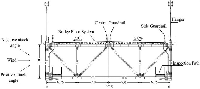
The flutter performance described in this paper was conducted on a single-span steel truss-stiffened girder suspension bridge. The overall bridge length is 1465 m and the span arrangement is 145 m+1060 m+260 m. The bridge girder is an orthotropic steel deck with a truss stiffening girder. The stiffening girder adopts a single-layer deck design scheme. The overall width and depth of the girder are 27.5 m and 7.0 m respectively. Fig. 1 shows the layout of the bridge elevation. Fig. 2 shows the steel-truss stiffening girder cross-section.
Fig. 1Layout of the bridge elevation (unit: m)
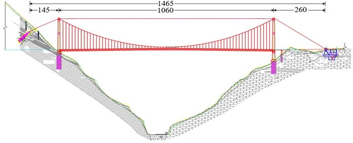
The bridge site is a deep mountainous canyon with steep terrain and complex topography. The basic wind speed at the bridge site is 29.54 m/s. The wind speed terrain correction coefficient is determined as 1.17 and the design reference wind speed at the height of the bridge deck is 34.56 m/s. The minimum required flutter checking wind speed is 52.9 m/s for attack angles between –3° and +3° and 37.0 m/s for ±5°. All of these parameters were determined based on the Chinese Wind-Resistant Design Specification for Highway Bridges [22].
Fig. 2Standard truss-stiffening girder cross-section (unit: m)
2.2. Modal analysis
As shown in Fig. 3, a three-dimensional finite element (FE) model of the bridge was first set up on the ANSYS platform according to the design scheme. The spatial beam element BEAM4 was used to simulate the truss members and bridge towers. Three degrees of freedom (3-D) spar element LINK8 was employed to model the main cables and suspenders. The main cables were laid on the towers. All masses and mass moments of inertia were equally distributed to the main girder with the MASS21 element. The soil-structure interaction was ignored in this study; hence, the anchorages and two main towers were considered fixed at the bases with all degrees of freedom locked. Based on the established FE model, the modal analysis of the bridge was carried out to compute the bridge dynamic characteristics which provide the data basis for wind tunnel tests. Table 1 lists the natural frequencies of some major modes of the bridge deck and associated mode descriptions.
Fig. 3Finite element model of the bridge
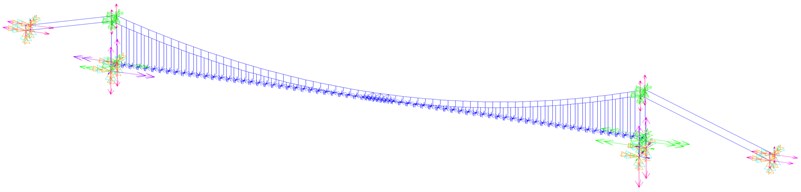
Table 1Natural frequencies and mode descriptions
Mode order | Frequency of prototype (Hz) | Mode description |
1 | 0.0624 | 1st order symmetric lateral bending of deck |
2 | 0.1053 | 1st order antisymmetric vertical bending of deck |
3 | 0.1608 | 1st order symmetric vertical bending of deck |
4 | 0.1869 | 1st order antisymmetric lateral bending of deck |
11 | 0.3168 | 1st order symmetric torsional bending of deck |
14 | 0.3934 | 1st order antisymmetric torsional bending of deck |
3. Sectional model wind tunnel tests
3.1. Sectional model and experimental setup
The sectional model representing the section of the bridge main span was designed and manufactured with a geometric scale ratio of 1:51.1 with a length of 2.095 m. The model was made as an exact rigid replica of the prototype. The main body of the model was constructed of high-quality wooden materials to ensure adequate stiffness. The attachments such as anti-collision guardrails and sidewalk railings on the deck were carved out of Acrylonitrile Butadiene Styrene (ABS) plastic plates to make sure the precise aerodynamic configuration simulation. Table 2 lists the design parameters of the sectional model for the flutter test.
Table 2Main test parameters of the sectional model
Properties | Parameters | Symbol | Unit | Prototype | Ratio | Model value |
Geometric scale | Height | M | 7 | 1/51.1 | 0.137 | |
Width | M | 27.5 | 1/51.1 | 0.538 | ||
Equivalent mass | Mass per unit length | Kg/m | 2.88E+04 | 1/51.12 | 11.013 | |
Mass moment of inertia | kg·m2/m | 3.36E+06 | 1/51.14 | 0.493 | ||
Frequency | Vertical frequency | Hz | 0.1608 | – | 1.472 | |
Torsional frequency | Hz | 0.3168 | – | 2.912 | ||
Damping ratio | Vertical damping ratio | % | – | 1 | 0.35 | |
Torsional damping ratio | % | – | 1 | 0.32 |
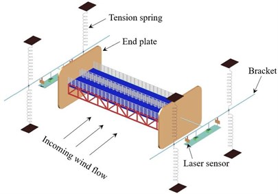
The sectional model wind tunnel tests were carried out in the test section of the XNJD-1 wind tunnel of Southwest Jiaotong University. The dimensions of the wind tunnel test section are 2.4 m (width) × 2.0 m (height) × 16.0 m (length). The wind speed can be continuously adjusted from 0.5 m/s to 45.0 m/s with a turbulent intensity lower than 0.5 % of the corresponding wind speed. The model is elastically mounted in the wind tunnel by eight tension springs to permit two degrees of freedom vibration system in vertical and torsional directions. Two metal support arms are connected at both ends of the model and to avoid disturbing the flow field, the metal support arms are located outside the wind tunnel wall. A pair of non-contact laser displacement sensors are used to measure the displacement of the model at upstream and downstream positions. All the tests are carried out under smooth oncoming flow conditions and wind attack angles of 0°, ±3°, and ±5° are considered. Fig. 4 shows the sectional model set-up in the wind tunnel. Fig. 5 illustrates the setup of spring supported sectional model test.
Fig. 4Sectional model installed in the wind tunnel
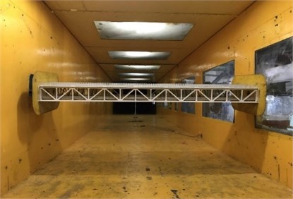
Fig. 5Setup of spring supported sectional model test
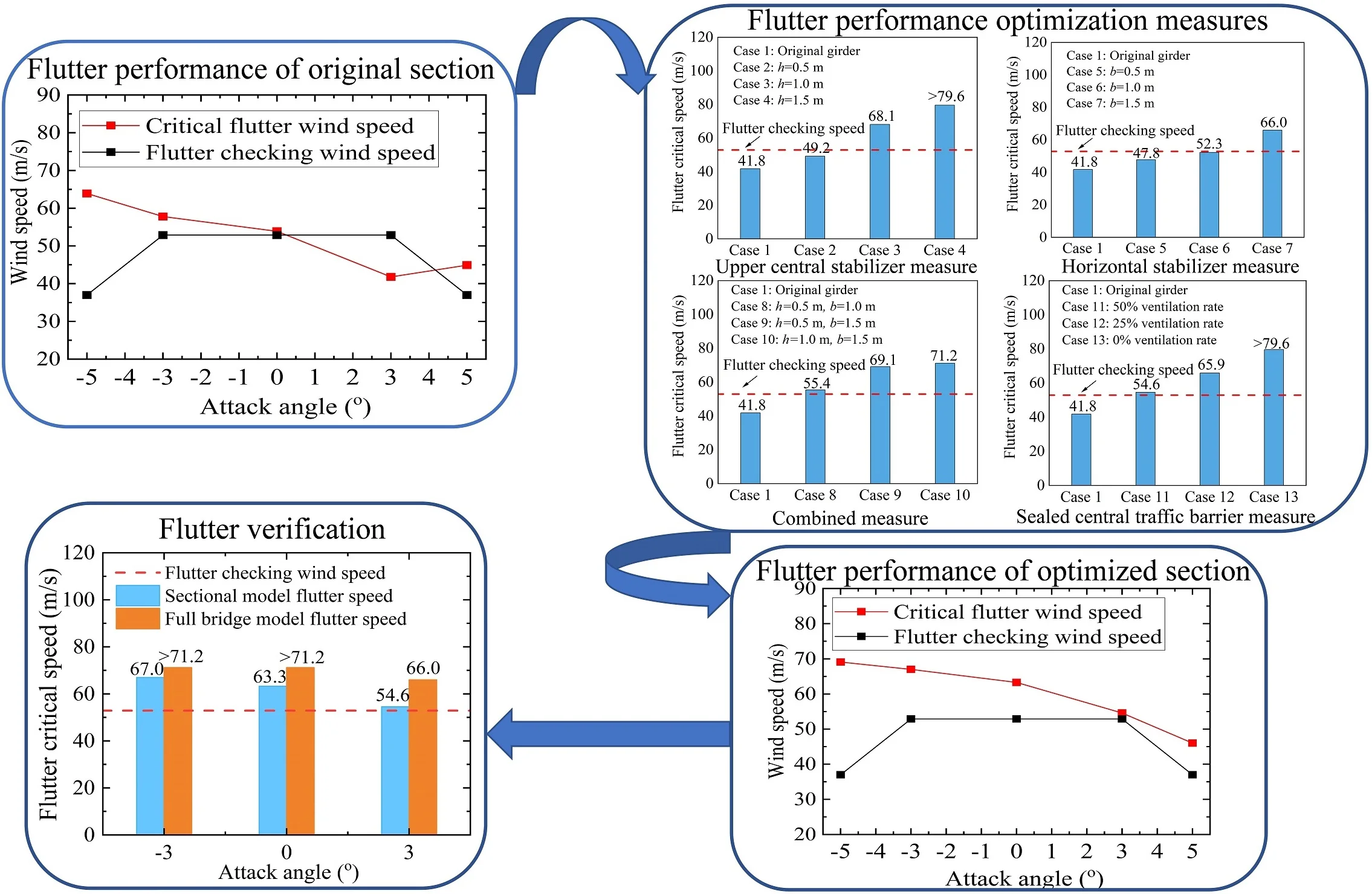
3.2. Flutter performance of original section
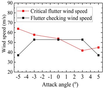
The critical flutter wind speed results of the original truss girder cross-section at the five tested attack angles are shown in Fig. 6. For the sake of comparison, the flutter checking wind speed results of the truss girder at the corresponding attack angles are also shown in Fig. 6. It should be noted here that the wind speed values have been transferred to the prototype values. From Fig. 6, it can be seen that for the attack angles ranging from –5° to +3°, the critical flutter wind speed exhibits a decreasing trend with an increase in absolute attack angle value. For the original truss girder at attack angles of 0°, –3°, and ±5°, the bridge demonstrates excellent flutter stability, whose flutter critical wind speed is substantially higher than the corresponding flutter checking wind speed. However, at an attack angle of +3°, the flutter critical wind speed is only 41.8 m/s, which is far below the requirement of 52.9 m/s, indicating the occurrence of flutter instability. The test results indicate that the flutter stability of the original truss girder at a wind attack angle of +3° fails to meet the Chinese wind-resistant design specification requirements for flutter. Therefore, countermeasures are needed to be taken into consideration to increase the critical flutter wind speed of the original girder cross-section at a wind attack angle of +3°, which is the most unfavorable attack angle for flutter instability.
Fig. 6Critical flutter wind speed of the original truss girder
3.3. Flutter performance optimization measures
Aerodynamic optimization measures are widely implemented for the suppression of flutter vibrations and increasing the flutter critical wind speed of a bridge girder. Based on the above test results, several aerodynamic countermeasures including the central upper stabilizer, horizontal stabilizer, combined central upper and horizontal stabilizers, and sealed central traffic barrier are tested to improve the flutter performance of the truss girder suspension bridge. All cases were conducted in a smooth flow at a wind attack angle of +3°. The effect of each aerodynamic countermeasure is investigated comprehensively and the flutter critical wind speed corresponding to various cases of each countermeasure is measured by sectional model wind tunnel tests.
3.3.1. Effect of upper central stabilizer
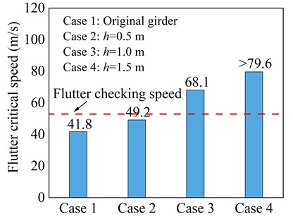
The central stabilizer installed above or below the deck surface is widely regarded as a promising passive aerodynamic countermeasure for flutter suppression. In this regard, the effect of the central stabilizer installed above the deck and in the middle of the central traffic barrier with three different dimensions as a countermeasure is first investigated. Fig. 7 illustrates the configuration of the upper central stabilizer, where represents the height of the stabilizer.
Fig. 8 shows flutter critical wind speed results for three cases of the upper central stabilizer. It can be seen that the upper central stabilizer has a considerable positive effect on the flutter performance of the bridge. Compared with the original girder cross-section, it can be noticed that when the height of stabilizing plate is greater than 0.5 m, the flutter critical wind speed exceeds the flutter checking wind speed and meet the wind-resistant code requirements for flutter.
Fig. 7Central upper stabilizer schematic diagram
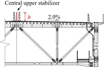
From the above discussion, it can be concluded that the flutter control effect of the central upper stabilizer is closely related to the height of stabilizing plate. It has been found that a sufficiently high stabilizing plate helps to a great extent in reducing the reattachment of the incoming flow and ultimately suppresses the torsional flutter of the truss girder. On the other hand, when the central upper stabilizing plate at small heights is installed, it does not effectively prevent the oncoming flow from reattachment and hence cannot notably increase the flutter critical wind speed of the main girder. Nevertheless, it is worth mentioning here that the high central upper stabilizing plate not only has a negative impact on the aesthetic appearance of the bridge but also hinders driving vision. In addition, it increases the wind load on the stiffening girder and the main girder buffeting response.
Fig. 8Critical flutter wind speed of central upper stabilizer measure
3.3.2. Effect of horizontal stabilizer
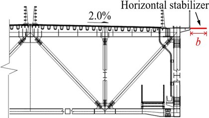
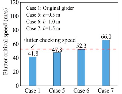
Horizontal stabilizer modifies the aerodynamic shape of the bridge deck, makes the cross-section streamline, and is a favorable aerodynamic countermeasure to improve the flutter stability of the bridge. The effect of the horizontal stabilizer installed symmetrically on both sides of the main girder and fixed on the upper chords with three different dimensions is tested. Fig. 9 illustrates the configuration of the horizontal stabilizer, where represents the width of the horizontal stabilizer.
Fig. 10 shows the flutter critical wind speed results for three cases of the horizontal stabilizer. It can be seen that after setting up horizontal stabilizing plates of width 0.5 m and 1.0 m, the onset of flutter velocity increases, however, critical flutter wind speed is still less than flutter checking speed and do not meet the code requirements for flutter. When the width of the horizontal stabilizer is increased from 1.0 m to 1.5 m, the girder has relatively improved flutter performance.
Fig. 9Horizontal stabilizer schematic diagram
It can be deduced that large geometric sizes are needed to obtain better flutter suppression effects. The results show that a small width horizontal stabilizing plate has no obvious improvement on the bridge flutter stability. The wider horizontal stabilizing plate from the standpoint of aerodynamics substantially weakens the reattachment of the oncoming wind flow on the upper surface of the deck and hence deemed favorable for the flutter performance of the truss girder. However, it should be noted that a wider horizontal stabilizing plate would negatively affect the aesthetics, design, and construction of the bridge.
Fig. 10Critical flutter wind speed of horizontal stabilizer measure
3.3.3. Effect of combined aerodynamic measure
Single aerodynamic measures, in some cases, cannot completely suppress all the wind-induced vibrations of bridges and are beneficial to mitigate only one kind of vibration. In addition, although the adoption of one aerodynamic countermeasure can successfully mitigate one kind of wind-induced vibration, it may give rise to the other vibration owing to the complex wind-structure interaction. Thus, it is greatly recommended to use a combination of aerodynamic countermeasures to effectively mitigate all the possible wind-induced vibrations of a bridge. Given this fact, three cases of combined central upper and horizontal stabilizers measure with varying geometric dimensions as countermeasures are considered. Fig. 11 illustrates the configuration of the combined aerodynamic measure.
Fig. 12 shows the flutter critical wind speed results for three cases of combined measure. It is worth mentioning here that the flutter critical wind speed is substantially higher than the flutter checking speed in all three cases of combined measure, demonstrating the excellent flutter stability of the bridge. In comparison to the single aerodynamic countermeasures, the use of combined measure effectively suppresses the flutter of the truss girder and increases flutter critical wind speed beyond the flutter checking speed in all three cases. However, taking into account the construction feasibility and economy, the application of combined measure does not only waste material but also advances difficulties for installation.
Fig. 11Combined measure schematic diagram
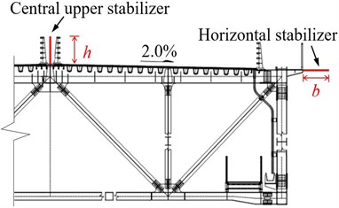
Fig. 12Critical flutter wind speed of combined aerodynamic measure
3.3.4. Effect of sealed central traffic barrier
Sealing the traffic barrier is an effective aerodynamic countermeasure that does not cause the additional cost of the structure. Sealing the barrier on the sides or center partially (with various ranges of ventilation rates) and completely (zero ventilation rate) plays a favorable role in improving the aerodynamic stability of the girder by suppressing the wind-induced vibrations, particularly flutter and vortex-induced vibrations. In this regard, three cases of sealed central traffic barrier with different sealing forms and regular vertical intervals were considered as shown in Fig. 13.
Fig. 13Sealed central traffic barrier schematic diagram: a) 50 % ventilation rate; b) 25 % ventilation rate; c) 0 % ventilation rate
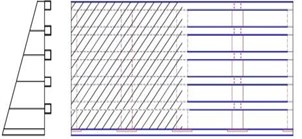
a)
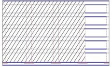
b)
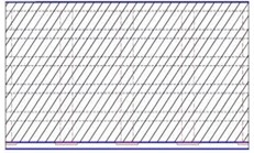
c)
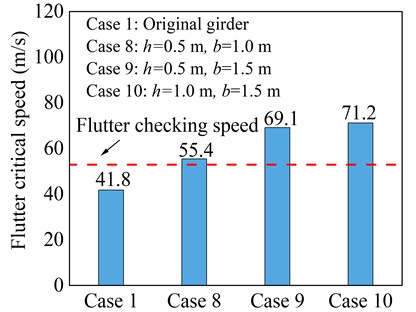
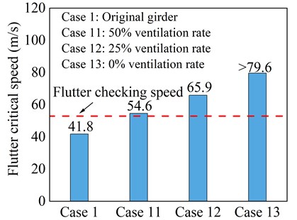
Fig. 14 shows the flutter critical wind speed results of the three test cases of sealed central traffic barrier measure. It can be seen that sealing the central traffic barrier with various ranges of ventilation rates contributes largely to the flutter stability of the bridge with flutter critical wind speed exceeding the code flutter checking wind speed value in all three cases tested. It can also be seen that ventilation rates significantly influence the flutter critical wind speed of the truss girder. Comparing the results of different cases revealed that the smaller ventilation rate results in comparatively larger flutter critical wind speed and has the best vibration mitigation effects.
Fig. 14Critical flutter wind speed of sealed central traffic barrier measure
3.4. Selection of the optimal aerodynamic countermeasure
By comparing the test results of various cases of the above flutter countermeasures from the perspective of construction feasibility, flutter code requirements, and economy, it can be observed that Case 11 which is a sealed central traffic barrier with a 50 % ventilation rate is the optimal aerodynamic optimization measure of the bridge against the most unfavorable wind attack angle (i.e., +3°). However, to ensure the effectiveness of optimal countermeasure for the remaining wind attack angles, sectional model tests with optimized truss girder are conducted and the corresponding flutter critical wind speed is measured.
Fig. 15Critical flutter wind speed of the optimized truss girder
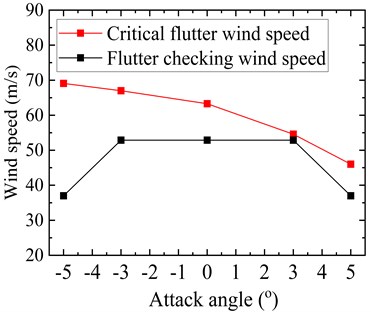
Fig. 15 shows the flutter critical wind speed results of the truss girder at the five tested attack angles after adopting the aerodynamic countermeasure. It can be noticed that the flutter critical wind speed exhibits a decreasing trend with an increase in absolute wind attack angle value. In contrast to the original girder cross-section, the flutter critical wind speed at both zero and negative wind attack angles as well as the most unfavorable attack angle (i.e., +3°) is remarkably increased. However, at an attack angle of +5°, there is little improvement in flutter critical wind speed. It is worth mentioning here that during the course of investigating the effectiveness of various aerodynamic countermeasures at large attack angles, it was observed that the flutter critical wind speed substantially increases by either installing a large size central stabilizing plate or completely sealing the central traffic barrier. However, a large central stabilizing plate adversely affects the aerostatic performance of the bridge deck. On the other hand, a completely sealed central traffic barrier may give rise to the vortex-induced vibrations of the bridge. For a completely sealed central traffic barrier, the oncoming wind flow pattern along the bridge length would be consistent. When the periodic vortex shedding is generated on the surface of the bridge, the associated energy of aerodynamic force is large which induces the vortex-induced vibrations. In contrast, for a partially sealed central traffic barrier, the oncoming wind flow pattern along the bride length would be different due to the presence of alternative sealed and non-sealed zones. Consequently, when the periodic vortex shedding occurs, the associated aerodynamic force energy is weakened which is beneficial for the suppression of vortex-induced vibrations. Therefore, a sealed central traffic barrier with a 50 % ventilation rate has proved to be the most optimal aerodynamic countermeasure. The measure has a significant impact not only at the most unfavorable wind attack angle but also at both zero and negative attack angles. Moreover, it maintained good stability at a large attack angle and satisfied the wind-resistant code requirements for flutter.
4. Verification of flutter via full-bridge test
The full-bridge aeroelastic model test comprehensively investigates the response of the bridge in uniform and turbulent wind flow conditions. Aeroelastic models simulate more truly the complex wind-structure interaction of the scaled models of the bridge in completion as well as erection stages. Moreover, aeroelastic model tests also validate the sectional model wind tunnel test results. Given this fact, a scaled full-bridge aeroelastic model was tested to validate the sectional model flutter stability results.
A full-bridge model constructed to a geometric scale of 1:100 was conducted in a low-speed XNJD-3 wind tunnel of Southwest Jiaotong University, which is at present the world’s largest wind tunnel. The cross-sectional dimensions of the tunnel are 22.5 m (width) × 4.5 m (height), and 36.0 m (length). When the wind tunnel is empty, the wind speed can be continuously adjusted from 0 to 16.5 m/s. The full-bridge model tests are carried out for the optimized girder cross-section in the bridge service state under wind attack angles of 0° and ±3° in uniform flow conditions. From the aeroelastic test, the flutter critical wind speed of the bridge deck was measured and compared with the sectional model flutter critical wind speed. Fig. 16 shows the photograph of the aeroelastic model installed in the wind tunnel.
Fig. 16Full bridge aeroelastic model in the wind tunnel
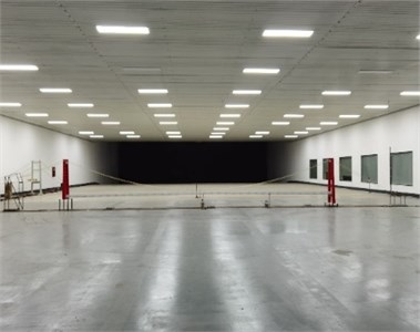
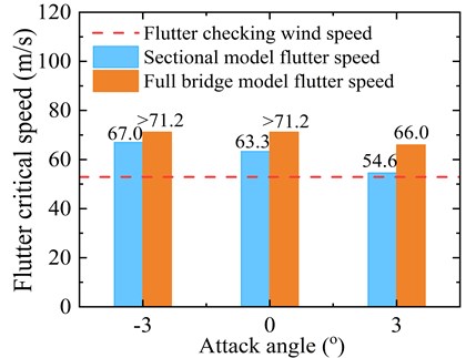
Fig. 17 shows the comparison of flutter critical wind speed results of the optimized girder cross-section obtained via sectional model and full-bridge model tests. It should be noted that the experimental wind speeds corresponding to the tested models have been transferred to the real bridge wind speed values. The test results show that the flutter stability of the girder in the sectional model and full-bridge model tests sufficiently meet the safety requirements with flutter critical wind speed exceeding the flutter checking wind speed for all the attack angles considered. This implies that the truss girder after adopting the aerodynamic countermeasure can effectively optimize the flutter performance of the bridge. It can be seen from Fig. 17 that at each attack angle the flutter critical wind speed value obtained from the full-bridge analysis is substantially higher than the sectional model tests. This is mainly because the aeroelastic full-bridge model captures more truly three-dimensional effects of the surrounding topography and oncoming wind flow. Moreover, aeroelastic models not only represent the bridge geometry in detail, but also accurately simulate the mass, stiffness, and damping properties of the deck, towers, and cables. The results of the full-bridge model test confirm the credibility of the sectional model tests and validate the effectiveness of the optimal aerodynamic countermeasure for suppressing the flutter of the truss girder cross-section.
Fig. 17Critical flutter wind speed of the optimized girder cross-section
5. Conclusions
In this paper, the flutter performance and the effects of various aerodynamic countermeasures on the flutter improvement of 1060 m truss-stiffened girder suspension bridge spanning mountainous canyon using wind tunnel tests of the sectional model and full-bridge model is analyzed. Based on the test results, the major conclusions can be made as follows:
1) The flutter stability of the bridge with the original truss girder section meets the wind-resistant design code requirement for flutter at all the tested attack angles except for +3°. At a +3° attack angle, the flutter critical wind speed is less than the code specified flutter checking wind speed value and needs to be improved.
2) The flutter performance optimization effect of the central upper stabilizer, horizontal stabilizer, and combined measure is closely related to the geometric dimension of the stabilizing plate. Large geometric dimensions significantly increase the flutter critical speed of the truss girder. On the other hand, for sealed central traffic barrier measure, the smaller ventilation rate results in a larger flutter critical speed of the girder. Sealed central traffic barrier with 50 % ventilation rate believed to be the most optimal aerodynamic measure in consideration of aerodynamic stability, economy, and safety.
3) The results of the aeroelastic full-bridge model test verified the effectiveness of the optimal aerodynamic measure adopted through a series of sectional model tests for suppressing the flutter of the truss girder cross-section. Considering the three-dimensional effects, the flutter performance of full-bridge is relatively better than that of sectional model tests.
References
-
K. Y. Billah and R. H. Scanlan, “Resonance, Tacoma Narrows bridge failure, and undergraduate physics textbooks,” American Journal of Physics, Vol. 59, No. 2, pp. 118–124, Feb. 1991, https://doi.org/10.1119/1.16590
-
A. Larsen, “Aerodynamic aspects of the final design of the 1624 m suspension bridge across the Great Belt,” Journal of Wind Engineering and Industrial Aerodynamics, Vol. 48, No. 2-3, pp. 261–285, Oct. 1993, https://doi.org/10.1016/0167-6105(93)90141-a
-
T. A. I. Kou-Xia and D. I. N. G. Da-Jun, “New leaps in construction of bridges in China,” Journal of Architecture and Civil Engineering, Vol. 23, No. 2, pp. 30–40, 2006.
-
T. Miyata, K. Yokoyama, M. Yasuda, and Y. Hikami, “Akashi Kaikyo bridge: Wind effects and full model wind tunnel tests,” in Aerodynamics of Large Bridges, Routledge, 2017, pp. 217–236, https://doi.org/10.1201/9781315136950-16
-
Y. Sun, H. Liao, and M. Li, “Experimental study on flutter performance of a 1700 m long truss girder suspension bridge,” in The 2016 Word Congress on Advances in Civil, Environmental, and Materials Research (ACEM 16), 2016.
-
B. Wu, X. Chen, Q. Wang, H. Liao, and J. Dong, “Characterization of vibration amplitude of nonlinear bridge flutter from section model test to full bridge estimation,” Journal of Wind Engineering and Industrial Aerodynamics, Vol. 197, No. 2, p. 104048, Feb. 2020, https://doi.org/10.1016/j.jweia.2019.104048
-
Y. Kubo, “Prospects for the suppression of aeroedynamic vibrations of a long-span bridge using boundary-layer control,” Journal of Vibration and Control, Vol. 10, No. 9, pp. 1359–1373, Sep. 2004, https://doi.org/10.1177/1077546304042050
-
H. Tang, Y. Li, Y. Wang, and Q. Tao, “Aerodynamic optimization for flutter performance of steel truss stiffening girder at large angles of attack,” Journal of Wind Engineering and Industrial Aerodynamics, Vol. 168, No. 9, pp. 260–270, Sep. 2017, https://doi.org/10.1016/j.jweia.2017.06.013
-
T. Ueda, M. Yasuda, and R. Nakagaki, “Mechanism of aerodynamic stabilization for long-span suspension bridge with stiffening truss-girder,” Journal of Wind Engineering and Industrial Aerodynamics, Vol. 33, No. 1-2, pp. 333–340, Mar. 1990, https://doi.org/10.1016/0167-6105(90)90048-h
-
H. Tang, Y. Li, and K. Shum, “Flutter performance and aerodynamic mechanism of plate with central stabilizer at large angles of attack,” Advances in Structural Engineering, Vol. 21, No. 3, pp. 335–346, Feb. 2018, https://doi.org/10.1177/1369433217717120
-
Z. Q. Chen, K. J. Ouyang, H. W. Niu, and X. G. Hua, “Aerodynamic mechanism of improvement of flutter stability of truss-girder suspension bridge using central stabilizer,” (in Chinese), China Journal of Highway and Transportation, Vol. 22, No. 6, pp. 53–59, 2009.
-
A. Al-Assaf, “Flutter analysis of open-trussed stiffened suspension bridges using synthesized aerodynamic derivatives,” Ph.D. dissertation, Washington State University, 2006.
-
H. Bai, N. Ji, G. Xu, and J. Li, “An alternative aerodynamic mitigation measure for improving bridge flutter and vortex induced vibration (VIV) stability: Sealed traffic barrier,” Journal of Wind Engineering and Industrial Aerodynamics, Vol. 206, No. 11, p. 104302, Nov. 2020, https://doi.org/10.1016/j.jweia.2020.104302
-
J. Liu, H. Liao, M. Li, and H. Mei, “Effect of stabilizer on flutter stability of truss girder suspension bridges,” Journal of Vibroengineering, Vol. 19, No. 3, pp. 1915–1929, May 2017, https://doi.org/10.21595/jve.2016.17954
-
T. Miyata and K. Yamaguchi, “Aerodynamics of wind effects on the Akashi Kaikyo Bridge,” Journal of Wind Engineering and Industrial Aerodynamics, Vol. 48, No. 2-3, pp. 287–315, Oct. 1993, https://doi.org/10.1016/0167-6105(93)90142-b
-
H. Xu, H. Liao, Y. He, and J. Zou, “Wind tunnel test of aerodynamic optimization measures for flutter stability of super long-span bridge with truss girder,” Journal of Highway and Transportation Research and Development (English Edition), Vol. 5, No. 2, pp. 49–54, Sep. 2011, https://doi.org/10.1061/jhtrcq.0000064
-
K. Wang, H. Liao, and M. Li, “Flutter suppression of long-span suspension bridge with truss girder,” Wind and Structures, Vol. 23, No. 5, pp. 405–420, 2016, https://doi.org/10.12989/was.2016.23.5.405
-
A. Fenerci, O. Øiseth, and A. Rønnquist, “Long-term monitoring of wind field characteristics and dynamic response of a long-span suspension bridge in complex terrain,” Engineering Structures, Vol. 147, No. 18, pp. 269–284, Sep. 2017, https://doi.org/10.1016/j.engstruct.2017.05.070
-
H. Tang, Y. Li, K. M. Shum, X. Xu, and Q. Tao, “Non-uniform wind characteristics in mountainous areas and effects on flutter performance of a long-span suspension bridge,” Journal of Wind Engineering and Industrial Aerodynamics, Vol. 201, No. 6, p. 104177, Jun. 2020, https://doi.org/10.1016/j.jweia.2020.104177
-
M.-J. Zhang, Y.-L. Li, H.-J. Tang, L.-D. Zhu, and Q.-Y. Tao, “Field measurement of wind characteristics at bridge site in deep gorge with high altitude and high temperature difference,” Zhongguo Gonglu Xuebao/China Journal of Highway and Transport, Vol. 28, No. 3, pp. 60–65, Mar. 2015.
-
Y. Li, X. Xu, M. Zhang, and Y. Xu, “Wind tunnel test and numerical simulation of wind characteristics at a bridge site in mountainous terrain,” Advances in Structural Engineering, Vol. 20, No. 8, pp. 1223–1231, Aug. 2017, https://doi.org/10.1177/1369433216673377
-
“Wind-resistant design specification for highway bridges,” (in Chinese), Ministry of Communications of the People’s Republic of China, JTG/T D60-01, 2004.
About this article

This research work was supported by “The National Natural Science Foundation of China” (Grant No. 51878580).
