Abstract
An aerodynamic optimization measure of the flutter stability of long-span suspension bridges with truss girder is presented in this paper. At first, the improvement of several kinds of central stabilizers and horizontal stabilizers on flutter stability is examined through series of section model and full aeroelastic model wind tunnel tests. Subsequently, the flutter derivatives of the truss girder with and without stabilizer are identified based on two degrees of freedom coupling free vibration method. Furthermore, based on the identified flutter derivatives, the critical flutter velocities of the truss girder section with and without stabilizer are analyzed through two dimensional flutter analysis method and the critical flutter velocities of the full bridge with and without stabilizer are analyzed through three dimensional method. Afterwards, the influence of each flutter derivative on the flutter stability of the truss girder is investigated. The results indicate that central upper stabilizer can effectively increase the critical flutter velocity of the truss girder. In contrast, the central lower stabilizer and horizontal stabilizer have less influence. Setting up central upper stabilizer leads to an obvious decrease in the value of the flutter derivatives and , while the flutter derivatives , , and are little influenced. The two dimensional and three dimensional flutter analysis results agree well with the sectional model and full model wind tunnel test results respectively.
1. Introduction
Steel truss girder is one of the major types of main girders of the suspension bridge in mountainous regions due to its large torsional stiffness, high ventilation ratio, suiting for complex wind environment, convenient transport and assembly. Compared with streamlined steel box girder, the truss girder has lower flutter stability. For the design of long-span truss girder suspension bridges, flutter stability is one of the most important themes.
Many researchers have carried out investigations on the flutter stability of long-span bridges. Matsumoto described the torsional flutter mechanism of 2D H-shaped cylinders and 2D rectangular cylinders with various side-ratios based on a series of wind tunnel tests. The mechanism of torsional flutter was classified into three types: velocity-restricted torsional flutter, vortex convection initiated torsional flutter and high speed torsional flutter. The torsional flutter was mainly controlled by the phase difference between separated flow from the leading edge and torsional response [1]. Ueda investigated the suppression effect of the vertical stabilizer on Akashi Kaikyo Bridge using flow visualization and pressure measurements. The test results concluded that the reattachment flow reseparated from the bottom edge of the vertical stabilizer, which led to the suppression of wind induced oscillation and increased the critical flutter velocity [2]. Larsen demonstrated the aerodynamics failure mechanism of the Tacoma Narrows Bridge based on numerical simulations and experimental results. It is shown that the instability mechanism is associated with the formation and drift of large vortices from the upwind edge of the bridge girder section; a structural modification of the girder cross section could suppress the vortex formation or counteracted the aerodynamic actions and thus rendered the bridge more aerodynamically stable [3]. Zhu evaluated the flutter instability of a truss-stiffened deck under skew winds via oblique sectional model wind tunnel tests. And the results showed the yaw wind effect could reduce the critical flutter velocity by about 7 % [4]. Yang studied the flutter controlling effect and aerodynamic mechanism of the central stabilizer on a thin plate section model. It is concluded that the appropriate central stabilizer could improve the flutter stability by increasing the participation level of heaving motion and changing the evolution trends of coupled aerodynamic dampings [5].
More recently, the improvements of stabilizers on flutter performance of steel truss girders have been concerned by some researchers. Chen predicted the flutter velocity of Aizhai Bridge with and without stabilizer by three-dimensional flutter analysis method. The analysis results show that using the central upper and lower stabilizers increases the extent of mode coupling between vertical-bending mode and torsional mode. And the increase of the mode coupling makes the flutter mode shift from single degree of freedom torsional vibration to coupling vibration between vertical-bending mode and torsional mode so that flutter frequency is decreased and flutter critical wind velocity is increased [6]. Liu investigated the flutter stability optimization effect of sealing the central slot, central upper stabilizer and central lower stabilizers through sectional model wind tunnel test. The test results show that simultaneously sealing the central slot with grating plate and installing central lower stabilizer inside the truss can enhance the flutter performance obviously [7]. Li carried out Systematic wind tunnel tests to investigate the validity of the aerodynamic measures of truss girder; the aerodynamic measures include central slot, central vertical stabilizer and horizontal stabilizer. The test results show that central slot reduces the critical flutter velocity of the truss girder section; the central vertical stabilizer can improve the flutter stability; the horizontal stabilizer has little effect on the flutter performance [8]. Wang tested the effect of the central upper stabilizer, central lower stabilizer and horizontal stabilizer on the flutter stability of truss girders based on three different types of truss girder of suspension bridge. The study shows that the different aerodynamic optimization solutions applied to distinct truss girders section [9, 10].
All of these studies suggested that installing appropriate stabilizers could suppress the wind-induced oscillation and improve the flutter stability of truss girder suspension bridges. Types of stabilizers include sealing plate of central slot, horizontal stabilizer, central upper stabilizer and central lower stabilizer. Besides, the shapes, install positions and dimensions of the stabilizers are different for different bridges. To sum up, the suitable stabilizers can be used as aerodynamic optimization measures of the flutter stability of long-span suspension bridges with truss girder. But the conclusions form studies on stabilizers are inconsistent and the study on suppression mechanism is rather little, which are necessary to study in detail.
In this paper, a long-span suspension bridge with steel truss girder is select as the study issue. At first, the flutter responses of the truss girder and the effects of various stabilizers on flutter stability are investigated through section model wind tunnel tests at a scale of 1:48. Subsequently, the flutter derivatives of the truss girder with and without stabilizer are identified based on two degrees of freedom coupling free vibration method. Furthermore, full aeroelastic model wind tunnel tests are carried out for further study on the effect of the central upper stabilizer. Afterwards, based on the identified flutter derivatives, the critical flutter velocities of the truss girder section with and without stabilizer are analyzed through two-dimensional flutter analysis method and the critical flutter velocities of the full bridge with and without stabilizer are analyzed through three dimensional method. Lastly, the influence of each flutter derivative on the flutter stability of the truss girder is investigated.
2. Dynamic characteristic analysis
The suspension bridge, selected as the engineering example, is a single span highway bridge with a main span of 1130 m as shown in Fig. 1. The structural model of the full bridge is created by using three-dimensional finite element methods. The main girder and towers are dispersed into beam elements; the main cables and the hangers are dispersed into link elements; the secondary dead loads are dispersed into mass elements; the boundary constraint conditions are applied according to the practical bridge. The dynamic characteristics of the bridge structure, which provides the data basis for the wind tunnel tests, are calculated by ANSYS finite element procedure. The structural natural frequencies and mode features are shown in Table 1.
Fig. 1Arrangement of the bridge (unit: m)
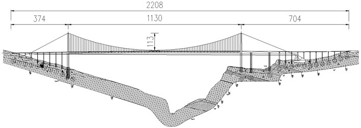
Table 1Structural natural frequencies and mode features
Mode order | Natural frequency (Hz) | Mode feature |
1 | 0.0844 | First order symmetric lateral bending |
3 | 0.1660 | First order antisymmetric vertical bending |
4 | 0.1777 | First order symmetric vertical bending |
8 | 0.3113 | First order symmetric torsion |
14 | 0.3887 | First order antisymmetric torsion |
3. Sectional model tests
As a first step for studying the flutter response, the section model is elastically mounted by 8 springs to simulate vertical and torsional modes of vibration in the suspension bridge. The section model tests were carried out in high-speed test section of XNJD-1 wind tunnel at Southwest Jiaotong University, the dimension of the test section is 2.4 m (width) × 2.0 m (height) × 16.0 m (length). Its wind speed is adjustable from 0.5 m/s to 45.0 m/s.
3.1. Sectional model and experimental setup
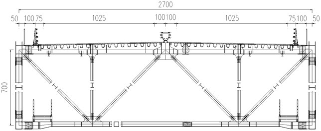
According to the standard cross section of the truss girder in completed bridge stage (shown in Fig. 2), the section model was designed and manufactured with scale ratio 1:48. The deck and the chords are constructed with hard pine to have sufficient rigidity while the web members, rails, struts and bracings are constructed with ABS plates.
Fig. 2Standard cross section (unit: cm)
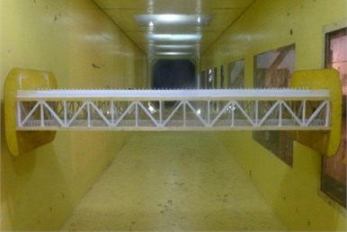
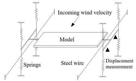
As shown in Fig. 3, the section model is elastically mounted in the wind tunnel by 8 extension springs through two metal support arms connected to each model end, and the model may move in vertical and torsional directions but the motion in along wind direction is restrained by steel wires. The metal support arms are placed out of the wind tunnel walls to avoid disrupting the flow field. The displacements of the model at upstream and downstream locations are measured by two laser displacement transducers. The test is conducted in smooth oncoming flow (turbulent intensity ~0.5 %), and –3°, 0°, +3° wind attack angles are considered.
Table 2Main test parameters of the sectional model
Parameter | Proto type | Section model |
Length (m) | – | 2.100 |
Width (m) | 27.0 | 0.563 |
Height (m) | 7.0 | 0.146 |
Equivalent mass (kg/m) | 25636 | 11.13 |
Equivalent moment of inertia (kg∙m2/m) | 3335858 | 0.628 |
Vertical vibration frequency (Hz) | 0.1777 | 3.37 |
Torsional vibration frequency (Hz) | 0.3113 | 5.75 |
Vertical damping ratio (%) | – | 0.45 |
Torsional damping ratio (%) | – | 0.48 |
Fig. 3Elastically-mounted sectional model
3.2. Data processing
The response data are recorded after the vibration become stable. The sampling frequency is 256 Hz and sample duration exceeds 30 s for each record. The wind velocity and the displacements of the model at upstream and downstream locations are measured in each test case. The two displacements and are used to calculate the vertical displacement and torsional displacement , as follows:
where is the distance between two measurement points of laser transducers.
3.3. Experimental results
The root-mean-square values of vertical and torsional displacement responses at different wind velocities are shown in Fig. 4. The results show that the critical velocity decreases with the increase of wind attack angle. The critical flutter velocities of the truss girder at different attack angles are listed in Table 3. The result clearly shows that the critical flutter velocity at –3° wind attack angle is higher than the flutter checking velocity according to the specification JTG/TD60-01 [11], while the critical velocities at 0° and +3° wind attack angle are lower than the checking velocity. It indicates there is some probability of occurring of flutter, which is not allowed in wind resistance design of bridges [12-19]. It is necessary to improve the flutter stability of the truss girder to prevent the appearing of flutter instability [20].
Fig. 4Root-mean-square values of vertical and torsional displacements
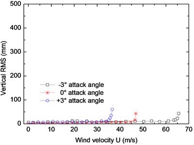
a) Vertical
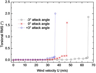
b) Torsional
Table 3Critical flutter velocity of the truss girder
Wind attack angle | Critical flutter velocity (m/s) | Flutter checking velocity (m/s) | Safety evaluation |
–3° | 65.0 | 46.6 | Safe |
0° | 46.5 | Unsafe | |
+3° | 36.1 | Unsafe |
3.4. Flutter performance optimization
Referring the related research results, 10 optimization measures, including central lower stabilizer, central upper stabilizer and horizontal stabilizer, are designed and studied through wind tunnel tests (marked in Table 4). The contrast tests are conducted at +3° wind attack angle, which is the most unfavorable attack angle for the flutter stability of the truss girder according to the test results in Table 3. The critical flutter velocities of each case (case 2-case 11) are measured by wind tunnel test and compared with the original design (case 1).
3.4.1. Central lower stabilizer
Two kinds of central lower stabilizers, with the height of 1.4 m (case 2) and 2.1 m (case 3) respectively, are installed to the main truss under the deck and tested successively. The influence of the central lower stabilizer on critical flutter velocity is shown in Fig. 5(a). With the change of height of the stabilizer, there are few changes on the critical flutter velocity comparing to the original section (case 1). It indicates the central lower stabilizer has little improvement on flutter stability of the truss girder.
3.4.2. Central upper stabilizer
The central upper stabilizer is placed at the intermediate position of the central crush barriers and fixed to the deck. Four kind of upper stabilizers are chosen to be investigated. The heights of the stabilizers are 0.9 m (case 4), 1.0 m (case 5), 1.1 m (case 6) and 1.15 m (case 7). The result in Fig. 5(b) shows the critical flutter velocity changes with the height of the central upper stabilizer. As it can be seen obviously, the critical velocity increases significantly when installing central upper stabilizers. The onset velocity increases by 18 %, 31 %, 43 %, 57 % after installing central upper stabilizer with the heights of 0.9 m, 1.0 m, 1.1 m, 1.15 m respectively. It can be deduced that central upper stabilizer could effectively improve the flutter stability of the truss girder and the greater the height of the upper stabilizer is, the higher the critical flutter velocity will be.
Table 4Aerodynamic optimization measures
Central lower stabilizer | 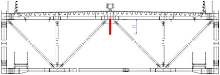 | Case 1: 0 m |
Case 2: 1.4 m | ||
Case 3: 2.1 m | ||
Central upper stabilizer | 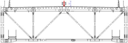 | Case 4: 0.9 m |
Case 5: 1.0 m | ||
Case 6: 1.1 m | ||
Case 7: 1.15 | ||
Horizontal stabilizer | 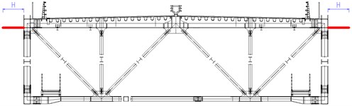 | Case 8: 0.75 m |
Case 9: 1.0 m | ||
Case 10: 1.1 m | ||
Case 11: 1.25 m |
Fig. 5Critical flutter velocity with central stabilizers (+3° wind attack angle)
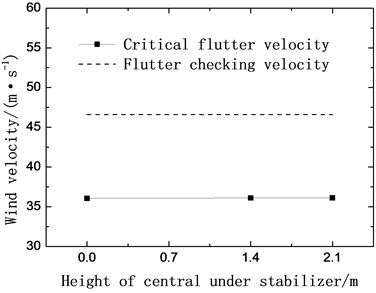
a) Lower stabilizers
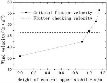
b) Upper stabilizers
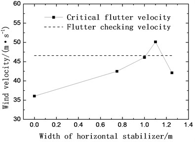
3.4.3. Horizontal stabilizer
The horizontal stabilizers are mounted on the both sides of the main girder symmetrically and fixed on the top chords. Four different horizontal stabilizers with the width of 0.75 m (case 8), 1.0 m (case 9), 1.1 m (case 10) and 1.25 m (case 11) are investigated. The critical flutter velocities of each case are examined through wind tunnel tests and shown in Fig. 6.
As shown in Fig. 6, the critical flutter velocity increases by 18 %, 28 % and 38 % with the width of horizontal stabilizer increasing from 0 to 0.75 m, 1.0 m and 1.1 m respectively. However, when the width of the stabilizer increases from 1.0 m to 1.1 m, the critical velocity is decreased by 16 % instead. It can be concluded that the horizontal stabilizer can evidently increase the critical flutter velocity, and the width of the stabilizer has an optimal value.
The experimental results indicate that installing the central upper stabilizer with a height exceeding 1.0 m or setting up the horizontal stabilizers of 1.1 m width both can increase the critical flutter velocity beyond the flutter checking velocity. Taking into consideration of optimization effect, aesthetic appearance, construction costs and daily maintenance, the central upper stabilizer of 1.0 m height (case 5) is selected to be the aerodynamic optimization measure for the truss girder suspension bridge.
Fig. 6Critical flutter velocity with horizontal stabilizers (+3 wind attack angle)
4. Flutter derivatives identification
Flutter derivatives are the basis for evaluating the flutter stability of the bridge structure. To study the aerodynamic mechanism of the central upper stabilizer on improving flutter stability of the truss girder, the cross sections of the truss girder without and with central upper stabilizer (case 5) are selected and the flutter derivatives of are identified by two degrees of freedom free vibration method.
4.1. Identification method
Scanlan and Huston described the self-excited forces with the flutter derivatives and (1-4), as follows [21-22]:
where, is the mass density of air; is the wind velocity; is the width of the deck; and represent the vertical and torsional reduced frequency respectively; and represent the vertical and torsional displacement. The self-exited lift force and moment of the vibration section model with two degree of freedom can be expressed as:
where and are the mass and inertia moment of the model per unit length respectively; and represent the vertical and torsional frequency of the model; and represent the vertical and torsional damping ratio of the model. Substituting Eq. (2) into Eq. (3) yields:
where represents the displacement time history of vertical and torsional vibration; is the mass matrix of the model system; and are the effective damping matrix and effective stiffness matrix of the model system. Based on the effective stiffness matrix and damping matrix of the model system under zero and non-zero wind velocity, the flutter derivatives can be written as:
where , , , . and respectively represent the stiffness matrix and damping matrix of the model system under zero wind velocity.
4.2. Identified results
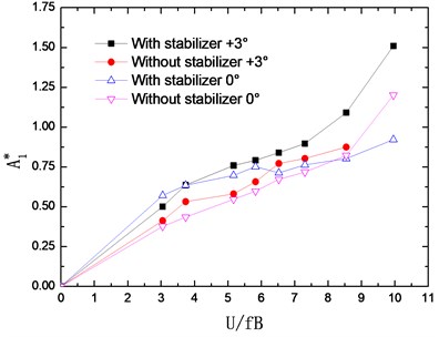
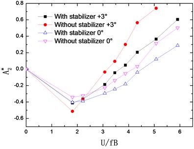
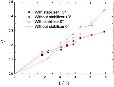
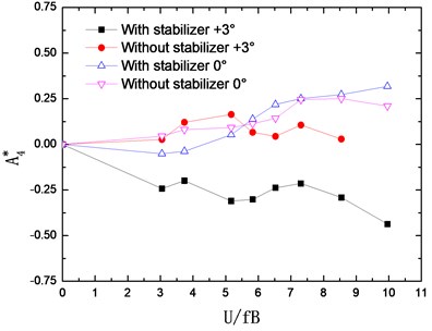
The flutter derivatives of the truss girder with and without stabilizer are identified in smooth flow and –0°, +3° wind attack angles are considered. The changing curves of flutter derivatives (1-4) with reduced wind velocities are shown in Fig. 7. Accordingly, Fig. 8 shows the changing curves of flutter derivatives (1-4).
Fig. 7Identified flutter derivatives Hi* (i= 1-4)
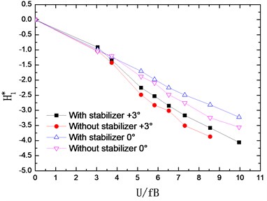
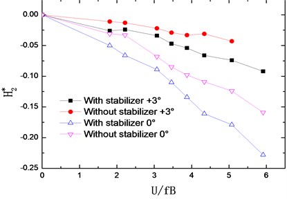
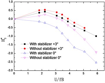
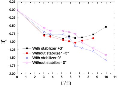
The flutter derivatives and , related to the torsional aerodynamic damping, have the greatest impact on the flutter stability of bridges. Particularly, shows the contribution of torsional velocity to pitch moment and behaves as an aerodynamic damping effect. A negative aerodynamic damping would be added to the bridge structure when the value of is positive, which is adverse to the aerodynamic stability. Conversely, the negative is beneficial for the flutter stability by adding a positive aerodynamic damping to the structure.
As shown in Fig. 7 and Fig. 8, the flutter derivatives and decrease evidently after installing the central upper stabilizer. This indicates the increase of the structural damping and the improvement of the flutter stability, which is in good agreement with the conclusion reached from the wind tunnel tests. Moreover, the central upper stabilizer also leads to a decrease in the value of and , but and have a relatively small impact on the flutter stability of the bridge. Additionally, with the central upper stabilizer installed, the value and tendency of flutter derivatives , , and are little influenced.
Fig. 8Identified flutter derivatives Ai* (i= 1-4)
5. Full aeroelastic model test
The stability of the whole bridge structure, considering the complex interactions of the main girder, main cables, towers and hangers, can be better studied via full aeroelastic model wind tunnel tests. For investigating the effect of the central upper stabilizer on flutter stability of the whole bridge structure, a full-bridge aeroelastic model at a scale of 1:100 was carried out in XNJD-3 boundary layer wind tunnel of Southwest Jiaotong University, the dimension of the test section is 22.5 m (width) × 4.5 m (height) × 36.0 m (length), shown in Fig. 9. The main parameters of the truss girder and the towers are listed in Table 5. The experimental parameters of the full model are summarized in Table 6.
The critical flutter velocities of the full aeroelastic model with and without central upper stabilizer are examined respectively under smooth flow. The influences of the central upper stabilizer on the critical flutter velocities of section model and full-bridge model are summarized in Table 7. The wind velocities have been translated to practical wind velocity at the bridge site.
The test results show that the central upper stabilizer increases the critical flutter velocity of the girder section model by 20 % and 31 % under 0° and +3° wind attack angle respectively. Correspondingly, the critical flutter velocity of the full aeroelastic model is increased by 33 % and 41 %. It can be concluded that central upper stabilizer can effectively improve the flutter stability of the truss girder suspension bridge.
Fig. 9Full aeroelastic model in wind tunnel
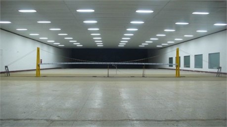
Table 5Main design parameters of the full model
Parameters | Scale | Proto type | Full model |
Length of girder (m) | 100 | 1130 | 11.30 |
Width of girder (m) | 100 | 27 | 0.27 |
Height of girder (m) | 100 | 7 | 0.07 |
Height of tower (m) | 100 | 230 | 2.30 |
Vertical stiffness of girder (N·m2) | 1005 | 1.39E+12 | 1.39E+02 |
Transverse stiffness of girder (N·m2) | 1005 | 4.58E+13 | 4.58E+03 |
Longitudinal stiffness of tower (N·m2) | 1005 | 2.63E+13 | 2.63E+03 |
Transverse stiffness of tower (N·m2) | 1005 | 2.60E+13 | 2.60E+03 |
Table 6Experimental parameters of the full model
Frequency | Damping ratio | Mode feature | |
Proto type | Full model | ||
0.0844 | 0.869 | 0.43 | First symmetric lateral bending |
0.1660 | 1.605 | 0.52 | First antisymmetric vertical bending |
0.1777 | 1.743 | 0.49 | First symmetric vertical bending |
0.2435 | 2.512 | 0.55 | First antisymmetric lateral bending |
0.3113 | 3.071 | 0.41 | First symmetric torsion |
Table 7Test results of critical flutter velocity
Wind attack angle | Section model | Full model | Flutter checking velocity | ||
Without stabilizer | With stabilizer | Without stabilizer | With stabilizer | ||
0° | 46.5 m/s | 56.0 m/s | 53.7 m/s | 71.2 m/s | 46.6 m/s |
+3° | 36.1 m/s | 47.2 m/s | 44.9 m/s | 63.1 m/s | |
6. Theoretical analysis
Regarding identified flutter derivatives as input parameters, the flutter performance of the section model and the full bridge are theoretical analyzed by a multi-mode based flutter analysis method [23].
6.1. Theoretical background
The governing equations of motion for a bridge excited by aerodynamic forces are given as:
where , , indicate the mass, damping and stiffness matrixes respectively; is the displacement vector; is the matrix of the self-excited forces described in Eq. (2).
The vertical motion and torsional motion of an element of the main girder can be expressed with interpolation functions as follows:
Substituting Eq. (7) into Eq. (2) and integrating, the aerodynamic forces of the girder element can be expressed as nodal force vector :
where and are matrixes of element aerodynamic forces related to the shape function and . Considering all the girder elements, the aerodynamic force matrix of the full bridge can be given as:
Selecting modes from the natural modes then the degree of freedom can be expressed as:
where are the generalized coordinates of the m modes.
Due to orthogonality property of the modes, the following is obtained by combining Eq. (6), (8) and (10):
where:
The generalized coordinates of the structure under the act of aerodynamic load are assumed to be:
by substituting Eq. (13) into (11), the following is obtained:
Let the , , Eq. (14) can be written as:
is one of the eigenvalues of Eq. (15). While the imaginary part of is near zero, the structure is in a critical self-excited vibration state under the aerodynamic load, and the flutter is about to take place. This is the critical flutter eigenvalue , and the critical flutter velocity and flutter frequency can be calculated as follows:
where is the reduced wind velocity corresponding to the flutter eigenvalue .
6.2. Analysis result
The critical flutter velocities of the main girder section and the full bridge are calculated through three dimensional flutter analysis procedures. Only the first order symmetric vertical bending mode and symmetric torsional mode are considered in predicting the onset velocity of the section model, while the flutter analysis of the full bridge is conducted by considering the first thirty modes. The comparison on the critical flutter velocity between theoretical analysis outcomes and wind tunnel test results is given in Table 8.
Comparing the critical flutter velocities of girder section and full bridge in Table 8, the theoretical calculation results are in agreement with the test results. Both the wind tunnel test results and theoretic calculation indicate that the central upper stabilizer can significantly increase the critical flutter velocity of the truss girder bridge.
Table 8Critical flutter velocity of theoretical calculation and test result
Wind attack angle | Stabilizer | Girder section | Full bridge | ||
Section model test | 2-D analysis | Full model test | 3-D analysis | ||
0° | Without | 46.5 m/s | 48.4 m/s | 53.7 m/s | 62.6 m/s |
With | 56.0 m/s | 60.5 m/s | 71.2 m/s | 87.4 m/s | |
+3° | Without | 36.1 m/s | 35.7 m/s | 44.9 m/s | 46.1 m/s |
With | 47.2 m/s | 44.6 m/s | 63.1 m/s | 60.5 m/s | |
6.3. Influence of each flutter derivative
To further investigate the influence of each flutter derivative on the flutter stability of the truss girder, the critical flutter velocities of the truss girder are calculated varying one flutter derivative at a time keeping all the others. As marked in Table 9, each flutter derivative of the truss girder without stabilizer ( and ) is substituted by the corresponding flutter derivative of the girder with the central upper stabilizer ( and ).
Table 9Results of flutter analysis of changing single flutter derivative
Flutter derivatives | Critical flutter velocity (m/s) | |
0° | +3° | |
, , , , , , , | 48.39 | 35.65 |
, , , , , , , | 48.43 | 35.66 |
, , , , , , , | 59.42 | 42.93 |
, , , , , , , | 48.49 | 35.71 |
, , , , , , , | 48.38 | 35.67 |
, , , , , , , | 48.39 | 35.65 |
, , , , , , , | 49.98 | 36.34 |
, , , , , , , | 48.32 | 35.71 |
, , , , , , , | 48.40 | 35.64 |
, : Flutter derivatives without stabilizer; , : Flutter derivatives with stabilizer | ||
The flutter analysis results in Table 9 show that the critical flutter velocity will increase by more than 20 % after substituting the original flutter derivatives with the , and there will be a 2 % increase when substituting the with . Whereas substituting the other flutter derivatives can only improve the critical flutter velocity less than 0.5 %. It can be concluded that flutter derivative is the key factor in improving the flutter stability of truss girder suspension bridge and has the secondary influence. While changing the values of the other six flutter derivatives has little impact on the calculation result of critical flutter velocity.
7. Conclusions
Section model and full aeroelastic model wind tunnel tests and theoretical calculation have been used to investigate the effect of the stabilizer on flutter stability of truss girder suspension bridge. The main conclusions can be drawn as follows:
The central upper stabilizer can effectively improve the flutter stability of the truss girder, and the horizontal stabilizer can evidently increase the critical flutter velocity but the width of the stabilizer has an optimal value.
The central upper stabilizer increases the critical flutter velocity of the section model by more than 20 % and leads to a 30 % increase in critical flutter velocity of the full aeroelastic model.
After installing the central upper stabilizer, the flutter derivatives and have an evident decrease, and also decrease in a certain degree, but the flutter derivatives , , and are little influenced.
The flutter analysis results show that the central upper stabilizer can significantly improve the flutter stability of the truss girder bridge and the theoretical calculation results are in good agreement with the test results.
The value of flutter derivative is the key factor in improving the flutter stability of truss girder suspension bridge and has the secondary influence, the other six flutter derivatives has little impact.
References
-
Matsumoto M., Daito Y., Yoshizumi F., Ichikawa Y., Yabutani T. Torsional flutter of bluff bodies. Journal of Wind Engineering and Industrial Aerodynamics, Vol. 69, Issue 71, 1997, p. 871-882.
-
Ueda T., Tanaka H., Matsushita Y. Aerodynamic stabilization for super long-span suspension bridges. Proceedings of IABSE Symposium Long-span and High-rise Structures, Kobe, Japan, 1998.
-
Larsen A. Aerodynamics of the Tacoma Narrows Bridge-60 years later. Structural Engineering International, Vol. 10, Issue 4, 2000, p. 243-248.
-
Zhu L. D., Xu Y. L., Guo Z. S., Tan X. Yaw wind effect on flutter instability of four typical bridge decks. Wind and Structures, Vol. 17, Issue 17, 2013, p. 317-343.
-
Yang Y. X., Ge Y. J., Xiang H. F. Flutter controlling effect and mechanism of central stabilizer. Journal of Tongji University, Vol. 35, Issue 2, 2007, p. 149-155.
-
Chen Z. Q., Ouyang K. J., Niu H. W., Hua X. G. Aerodynamic mechanism of improvement of flutter stability of truss girder suspension bridge using central stabilizer. China Journal of Highway and Transport, Vol. 22, Issue 6, 2009, p. 53-59.
-
Liu J., Liao H. L., Ma C. M. Study on flutter stability optimization of truss suspension bridge in mountainous region. Journal of Wuhan University of Technology (Transportation Science and Engineering), Vol. 38, Issue 3, 2014, p. 637-640.
-
Li C. G., Zhang Z. T., Chen Z. Q., Liao J. H. Experimental study on the aerodynamic stability measure of a suspension bridge with truss stiffening girder. Journal of Vibration and Shock, Vol. 27, Issue 9, 2008, p. 40-43.
-
Wang K., Liao H. L., Liu J. Wind resistance tests for long-span steel truss bridges across gorges of mountainous area. Journal of Vibration and Shock, Vol. 33, Issue 19, 2014, p. 169-174.
-
Wang K., Liao H. L., Li M. S. Flutter suppression of long-span suspension bridge with truss girder. Wind and Structures, Vol. 23, Issue 5, 2016, p. 405-420.
-
JTG/T D 60-01. Wind-resistent Design Specification for Highway Bridges. Communications Press, Beijing, China, 2004, (in Chinese).
-
Gu B., Sun X., Sheng V. S. Structural minimax probability machine. IEEE Transactions on Neural Networks and Learning Systems, 2016, p. 1-11.
-
Gu B., Sheng V. S., Tay K. Y., Romano W., Li S. Incremental support vector learning for ordinal regression. IEEE Transactions on Neural Networks and Learning Systems, Vol. 26, Issue 7, 2014, p. 1403-1416.
-
Pan Z. Q., Zhang Y., Kwong S. Efficient motion and disparity estimation optimization for low complexity multiview video coding. IEEE Transactions on Broadcasting, Vol. 61, Issue 2, 2015, p. 166-176.
-
Fu Z. J., Ren K., Shu J. G., Sun X. M., Huang F. X. Enabling personalized search over encrypted outsourced data with efficiency improvement. IEEE Transactions on Parallel and Distributed Systems, 2015, https://doi.org/10.1109/TPDS.2015.2506573.
-
Gu B., Sheng V. S. A robust regularization path algorithm for ν-support vector classification. IEEE Transactions on Neural Networks and Learning Systems, 2016, https://doi.org/10.1109/TNNLS.2016.2527796.
-
Zheng Y. H., Jeon B., Xu D. H., Wu Q. M. J., Zhang H. Image segmentation by generalized hierarchical fuzzy C-means algorithm. Journal of Intelligent and Fuzzy Systems, Vol. 28, Issue 2, 2015, p. 961-973.
-
Xia Z. H., Wang X. H., Sun X. M., Liu Q. S., Xiong N. X. Steganalysis of LSB matching using differences between nonadjacent pixels. Multimedia Tools and Applications, Vol. 75, Issue 4, 2016, p. 1947-1962.
-
Wen X. Z., Shao L., Xue Y., Fang W. A rapid learning algorithm for vehicle classification. Information Sciences, Vol. 295, Issue 1, 2015, p. 395-406.
-
Jeoung C., Park S. B., Kim W. S., Cho D. Y. Wind oscillation analysis of a suspension bridge coupled with CFD. Journal of Vibroengineering, Vol. 17, Issue 1, 2015, p. 487-495.
-
Scanlan R. H. Air foil and bridge deck flutter derivatives. Journal of Soil Mechanics and Foundations Division, Vol. 97, Issue 6, 1971, p. 1717-1737.
-
Huston D. R. The Effects of Upstream Gusting on the Aeroelastic Behavior of Long Suspended-Span Bridges. Ph.D. Dissertation, Princeton University, Princeton, 1986.
-
Hua X. G., Chen Z. Q. Wind-induced flutter analysis of long-span bridges with fully automatic searching method. Engineering Mechanics, Vol. 19, Issue 2, 2002, p. 68-72.
Cited by
About this article

The support for this work was provided in part by National Program on Key Basic Research Project (Grant No. 2013CB036300) and National Natural Science Foundation of China (Grant No. 51378442 and No.51408505).
