Abstract
This paper presents a limit cycle oscillation (LCO) suppression method of nonlinear aeroelastic system based on adaptive neuro-fuzzy control. A prototypical 2D wing section with a single control surface at the trailing edge of the main wing, which contains a symmetrical freeplay nonlinearity in the pitch degree of freedom, is modelled by SIMULINK (Matlab 2016R) to illustrate the proposed method. Proportional integral differential (PID) controller is used to suppression the LCO of nonlinear aeroelastic system. The control law of the PID controller is identified by neural network. A new fuzzy control law of the nonlinear aeroelastic system is obtained by adjusting the parameters of the fuzzy control system. A nonlinear aeroelastic system with measurement noise in the measurement feedback loop is conducted to verify the effectiveness of the proposed method.
1. Introduction
Recently, there has been growing interest in active control technology of the nonlinear aeroelastic system, which suppresses and alleviates aeroelastic problems via control surface on the wing. Active flexible wing (AFW) technology, which uses a nonlinear programming technique and an analogy with linear quadratic Gaussian solution, is developed to suppress the flutter. The general method is applied to synthesise an active flutter suppression control law for an aeroelastic wind tunnel wing model. Experimental results show that the AFW technology can successfully suppress the flutter [1-4]. Active aeroelastic wing technology, which uses wing aeroelastic flexibility, integrates aerodynamics, active controls and advanced technology structures to maximise aircraft performance, and its key aspects were tested on an F/A-18 testbed [5]. However, these studies do not consider the effect of nonlinear factors, and this nonlinearity may cause various aeroelastic phenomena, such as limit cycle oscillation (LCO), bifurcation and chaos [6, 7].
A globally stable nonlinear adaptive control method, which uses partial feedback linearization techniques, was proposed to suppress the LCO of a typical airfoil section with structural nonlinearities [8]. Vipperman et al. investigated and tested an active control method for a typical wing section, which utilizes the models obtained from system identification [9, 10]. A compensator, which uses the linear quadratic Gauss optimization scheme, was designed to suppress the LCO caused by the freeplay nonlinearity of the control surface [11]. However, the bifurcation structures, which are widely existing in the closed-loop control system, will affect system stability [12]. In the past few years, many researchers have focused on robust control to improve the stability of the control system [13, 14]. Modern control theory, which is based on state space method, requires the establishment of an accurate mathematical model of the controlled object. Influenced by uncertainties of the control system, including the accuracy of unsteady aerodynamic calculation, the error of structural dynamics modelling and the group delay of filters in control loops, modelling aeroservoelastic systems is difficult, which adds complexity when designing the control law of active flutter suppression.
Fuzzy control does not require a precise mathematical model of the controlled object and is suitable for complex control systems that are difficult to model. Fuzzy logic control has been widely used to control the nonlinear systems [15-19]. In recent decades, fuzzy control has been applied to aeroelastic system control. An adaptive decoupled fuzzy sliding-mode control is derived to control the plunge and pitch motions of an aeroelastic system [20, 21]. Li proposed an aeroelastic system LCO suppression method via an adaptive fractional-order fuzzy controller [22]. These studies have shown that the fuzzy control algorithm is better than the traditional control methods. However, the fuzzy control algorithm, which must constantly adjust the control rules, is difficult to optimize and the debugging cycle is long when it is applied to a complex or time-varying controlled object.
This article is organized as follows: Section 2 introduces a prototypical two dimensional wing section with freeplay in the pitch, which adopts a single trailing edge flap as the control input signal. In Section 3, the framework of adaptive neuro-fuzzy control for the nonlinear aeroelastic system is presented. Traditional proportional integral differential (PID) controller is used to generate the initial control parameters. Takagi-Sugeno (T-S) [23] model is adopted to construct the fuzzy logic system. Neural network is used to identify the fuzzy control rules. In Section 4, the proposed algorithm is tested by two sets of numerical experiments: a nonlinear aeroelastic system without measurement noise and the other one with 20 dB measurement noise. Finally, conclusions are drawn in Section 5.
2. Nonlinear aeroelastic system model
Following the strategy employed in Reference [24], we seek to adopt the simplest representation of the aeroelastic system as possible. Fig. 1 illustrates a schematic of the prototypical 2D wing section with a control surface at the trailing edge of the main wing.
Fig. 1Schematic of the prototypical 2D wing section [24]
![Schematic of the prototypical 2D wing section [24]](https://static-01.extrica.com/articles/21738/21738-img1.jpg)
In this system, represents the airfoil chord; is the semi-chord of the wing section; and represent the plunge and pitch of the main wing, respectively; indicates the flap of the control surface; is the non-dimensional distance between the mid-chord and elastic axis; represents the non-dimensional distance between the mass center and elastic axis; and denote the stiffness coefficients of the wing in plunge and pitch, respectively; and and refer to the quasi-steady aerodynamic lift and moment of force, respectively.
The governing equations of motion for the structure of the nonlinear aeroelastic system can be written as follow:
where represents the mass of the wing section; is the moment of the inertia about the elastic axis; and represent the structural damping coefficients of the wing in plunge and pitch, respectively; and is the moment–rotation relationship of pitch angle (). The moment characteristic of a symmetrical freeplay nonlinear system is expressed as:
where is the system gap.
and refer to the quasi-steady aerodynamic lift and moment of force, which could be modeled as follows:
where represents the free-stream density; is the inflow velocity; and are the lift and moment coefficient per angle of attack, respectively; and are the lift and moment coefficient per control surface deflection (), respectively.
Substituting Eq. (3) and Eq. (4) into Eq. (1) yields:
Defining:
Then, the governing equations of motion could be written as follow:
The transformed equations of motions in the state space form become:
where:
3. Description of fuzzy control system
Fuzzy logic control is a computer digital control method based on fuzzy set theory, fuzzy linguistic variables and fuzzy logic inference. This method is an important and effective form of intelligent control. Fuzzy control does not depend on the precise mathematical model of the controlled object, and has good robustness and adaptability. This method is especially suitable for controlling nonlinear, time-varying, delayed and model-incomplete systems. Due to the complexity of the nonlinear aeroelastic system, it is difficult to get the predefined model structure of the variable characteristics in the system. Adaptive neuro-fuzzy control, which is based on the neural network identification algorithm, utilizes the strong learning capability of the neural network, the direct processing ability of quantitative data and the strong structural knowledge expression capability of fuzzy logic. Fig. 2 shows the flow chart of adaptive neuro-fuzzy control for the nonlinear aeroelastic system.
Fig. 2Flow chart of adaptive neuro-fuzzy control
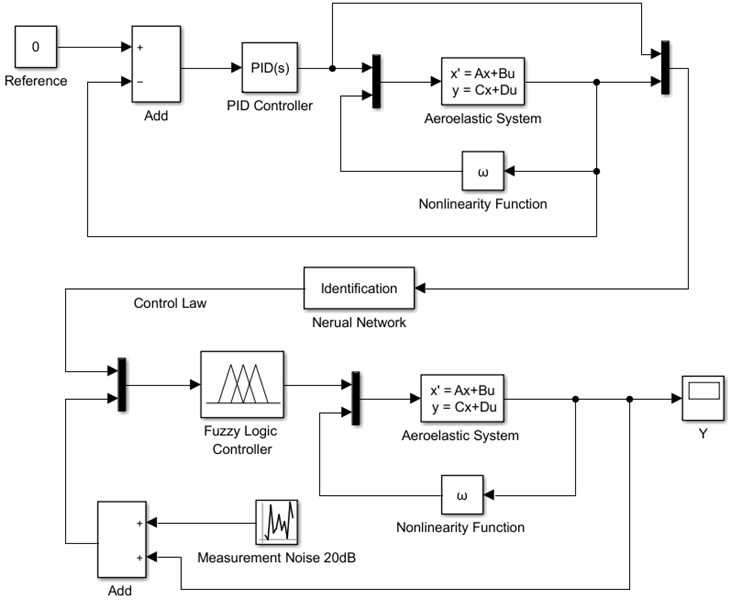
The input signal of the PID controller is the difference between the system feedback and reference signal. The purpose of the controller is to suppress the LCO of the aeroelastic system, which requests the reference signal to be the constant signal (). Nonlinear function is used to simulate the system nonlinearity. The input signals of the adaptive neural network are the control and output signals of the PID control system, and the control law of the fuzzy logic control system is obtained after the training of the neural network. Finally, a fuzzy control system is used to control the nonlinear aeroelastic system.
The key point of fuzzy logic control is to map the input space to the output space. The main mechanism for achieving this goal is a list of If-Then statements called rules. Fuzzy inference refers to the process of mapping a given input to an output by using fuzzy logic. The fuzzy inference process comprises five parts: fuzzification of the input variables, application of the fuzzy operator (AND or OR) in the antecedent, implication from the antecedent to the consequent, aggregation of the consequents across the rules and defuzzification.
Mamdani [25] and T-S are the two commonly used fuzzy inference models. The Mamdani model is among the first control systems built using fuzzy set theory, and its advantage is intuitive. However, this model expects the output member functions to be fuzzy sets, which must be defuzzified for each output variable after the aggregation process. The T-S model is a more compact and computationally efficient representation than the Mamdani model, and it is suitable for optimization and adaptive technology. The fuzzy inference system in this study adopts the T-S model.
The T- model of a dual-input-single-output system with fuzzy rules is shown as follows:
where is the basis of fuzzy rules and denotes the th rule, which can be written as:
where and are the inputs of the fuzzy inference system, indicates the output of the th fuzzy rule, and denote the fuzzy sets of the th rule and , and are constants, the values of which are determined by identifying from a large number of input-output test data of the system. For the zero-order T-S method, the output value is a constant.
The output of the control system is the weighted average value of the output of all single rules:
where is the weight of th rule, which can be calculated by Eq. (21) or (22):
4. Numerical simulation examples
For linear aeroelastic systems, the critical flutter velocity can be obtained through eigenvalue analysis. Given the influence of nonlinearity, the flutter speed of the system decreases, and the system response presents LCO when the inflow velocity is relatively low. By using the system parameters listed in Table 1 [12], the initial conditions are set to 0.03, 0, 0, and 0. The critical flutter velocity of the linear system is obtained as = 12.1 m/s; the critical flutter velocity is 11.7 m/s when a symmetrical gap exist in the system; and the LCO occurs when the inflow velocity is 11.0-11.7 m/s.
Table 1Nonlinear aeroelastic system parameters [12]
Parameter | Value |
, kg/m3 | 1.225 |
, m | 0.135 |
, kg | 12.387 |
0.2466 | |
−0.6 | |
, kg·m2 | 0.065 |
, Ns/m | 27.43 |
, Nms | 0.180 |
, N/m | 2844.2 |
, Nm/rad | 2.82 |
6.28 | |
3.358 | |
−0.628 | |
−0.635 | |
, rad | 0.04 |
4.1. Results of the PID controller
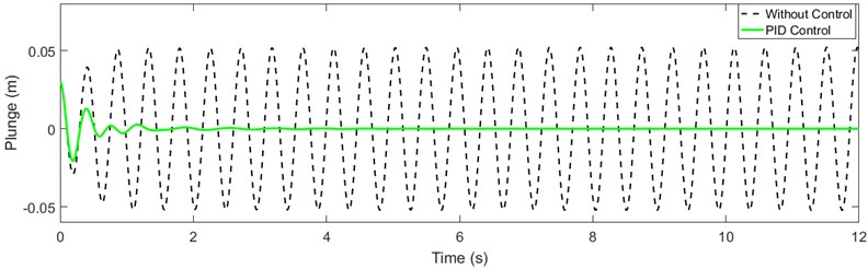
PID control is the earliest and most widely used method in automatic control. In this study, the PID controller is utilized to generate the original data for the neuro-fuzzy control. The inflow velocity is set to = 11.6 m/s. The response results of the PID control system of the gap nonlinear aeroelastic system are obtained, as shown in Fig. 3.
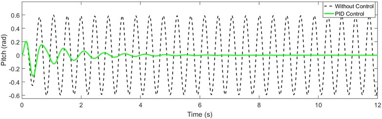
Fig. 3Response of the aeroelastic system: a) plunge direction and b) pitch direction
a)
b)
Fig. 3(a) and 3(b) present the responses of the aeroelastic system in the plunge and pitch directions, respectively. When the controller is not used, periodic equal amplitude oscillation (LCO) occurs in the plunge and pitch directions of the system. When the PID controller is used, the oscillation decreases gradually. Results indicate that the LCO of the nonlinear aeroelastic system can be suppressed by the PID controller. Fig. 3 indicates that the LCO is mainly in the pitch direction because the system nonlinearity is the stiffness nonlinearity in that direction. The pitch direction response of the system is subsequently investigated.
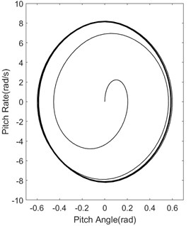
Fig. 4Pitch direction phase diagram of the system: a) without controller and b) PID controller
a)
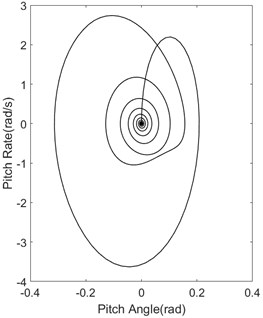
b)
The pitch direction phase diagram of the system are depicted in Fig. 4. Fig. 4(a) exhibits the pitch direction phase diagram of the system without the controller. The system does not converge, but it is a stable LCO. Fig. 4(b) represents the pitch direction phase diagram of the system with the PID controller. The system gradually converges and the LCO is suppressed.
Fig. 5Output signal of the PID controller
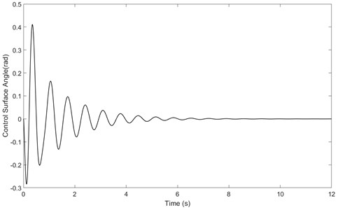
The output signal of the PID controller is shown in Fig. 5. The PID controller suppresses the LCO in 5 s and tends to be stable gradually.
4.2. System without measurement noise
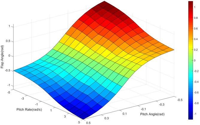
After the input and output data of the PID controller are obtained, the control law of the fuzzy control system similar to the PID controller can be obtained by using the neural network identification method. The parameters of the membership function are adjusted by using the back-propagation algorithm alone or with the least square method. Fig. 6 presents the control law diagram for training the input and output data of the PID controller. The graph shows that the input and output parameters of the fuzzy controller coincide with the PID controller. The input signal should be symmetrical on the basis of the characteristics of the nonlinear aeroelastic system with symmetrical freeplay. Therefore, the input membership function is adjusted to a symmetrical form, and the control law of the fuzzy inference system is regenerated, as shown in Fig. 7. The adjusted control law surface is an S-shaped surface. In Fig. 6 and Fig. 7, different colors represent different flap angles of the control surface (), which is determined by pitch angle and pitch rate of the nonlinear aeroelastic system.
Fig. 6Control law of the trained fuzzy controller
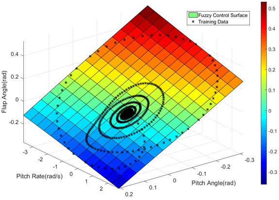
Fig. 7Adjusted control law diagram of the fuzzy inference system
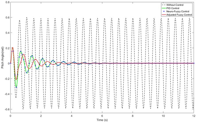
The responses of nonlinear aeroelastic system without measurement noise controlled by different algorithms are given in Fig. 8. The black dotted line represents the response of the pitch direction of the nonlinear aeroelastic system without the controller, the green solid line indicates the response of the system using the PID controller, the blue asterisk signifies the response of the system using the neuro-fuzzy controller and the thick red solid line denotes the response of the system using the adjusted fuzzy controller. The neural network can accurately identify the control law of the PID controller (the control effect of both is identical), and the adjusted fuzzy control has a shorter convergence time and better control effect than the PID controller.
Fig. 8Results of nonlinear aeroelastic system without measurement noise
4.3. System with measurement noise
In the real control system, the measurement noise is inevitable in the measurement feedback loop. In order to test the LCO suppression effect of the adaptive controller in the presence of measurement noise, a 20 dB measurement noise is added to the pitch and pitch rate signals of the nonlinear aeroelastic system. Fig. 9 show the pitch and pitch rate feedback signals of the nonlinear aeroelastic system with measurement noise, when the controller is turned on after 5 s. Fig. 10 displays the deflection command of control surface when the system with measurement noise.
Fig. 9Pitch and pitch rate signals of nonlinear aeroelastic system with measurement noise
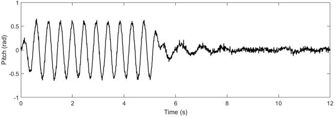
a)
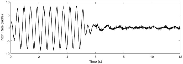
b)
Fig. 10Deflection command of control surface
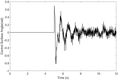
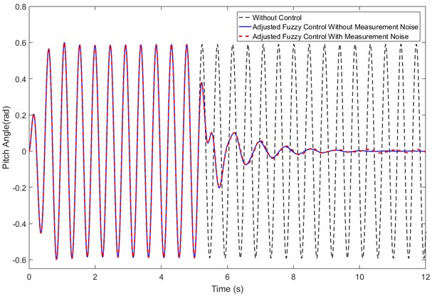
The responses of nonlinear aeroelastic system with measurement noise controlled by adjusted fuzzy controller is shown in Fig. 11. The black dotted line represents the response of the pitch direction of the nonlinear aeroelastic system without controller; the blue solid line denotes the response of the system without measurement noise using the adjusted fuzzy controller; the red dotted line denotes the response of the system with measurement noise using the adjusted fuzzy controller. The results show that the proposed control method can still suppress the LCO in the presence of measurement noise. Due to the measurement noise, the system response does not converge to zero as it does without measurement noise, but fluctuates around the x-axis. Because the nonlinear aeroelastic system is equivalent to a low-pass filter [24], the system response does not appear high-frequency vibration as shown in Fig. 10.
Fig. 11Results of nonlinear aeroelastic system with measurement noise
5. Conclusions
In this article, a LCO suppression method of nonlinear aeroelastic system based on adaptive neuro-fuzzy control is proposed. The original control parameters (data) of LCO suppression for nonlinear aeroelastic systems are generated by a PID controller, and the control rules of the PID controller are identified by the neural network. The membership function of the fuzzy control system is adjusted in accordance with the LCO characteristics of the nonlinear aeroelastic system. Two examples, one without measurement noise and the other one with 20 dB measurement noise, are conducted to verify the proposed fuzzy control algorithm. Simulation results show that the neural network can accurately identify the control law of the PID controller, and the adjusted fuzzy control law has a better performance than the PID controller. The advantages of the proposed method are summarized as follows:
1) The adaptive neuro-fuzzy control method can be used for active flutter suppression of strongly nonlinear aeroelastic systems without establishing accurate mathematical models.
2) The established control method is easy to optimize and no need to constantly adjust the control rules when used to suppress LCO of nonlinear aeroelastic systems with measurement noise.
References
-
Mukhopadhyay V., Newsom J. R., Abel I. Reduced-order optimal feedback control law synthesis for flutter suppression. Journal of Guidance, Control, and Dynamics, Vol. 5, Issue 4, 1982, p. 389-395.
-
Mukhopadhyay V. Digital robust control law synthesis using constrained optimization. Journal of Guidance, Control, and Dynamics, Vol. 12, Issue 2, 1989, p. 175-181.
-
Mukhopadhyay V. Flutter suppression control law design and testing for the active flexible wing. Journal of Aircraft, Vol. 32, Issue 1, 1995, p. 45-51.
-
Waszak M. R., Srinathkumar S. Flutter suppression for the active flexible wing: a classical design. Journal of Aircraft, Vol. 32, Issue 1, 1995, p. 61-67.
-
Pendleton E. W., Bessette D., Field P. B., Gerald D. M., Kenneth E. G. Active aeroelastic wing flight research program: technical program and model analytical development. Journal of Aircraft, Vol. 37, Issue 4, 2000, p. 554-561.
-
Lee B. H. K., Tron A. Effects of structural nonlinearities on flutter characteristics of the CF-18 aircraft. Journal of Aircraft, Vol. 26, Issue 8, 1989, p. 781-786.
-
Lee B. H. K., Price S. J., Wong Y. S. Nonlinear aeroelastic analysis of airfoils: bifurcation and chaos. Progress in Aerospace Sciences, Vol. 35, 1999, p. 205-334.
-
Ko J., Kurdila A. J., Strganac T. W. Nonlinear control of a prototypical wing section with torsional nonlinearity. Journal of Guidance, Control, and Dynamics, Vol. 20, Issue 6, 1997, p. 1181-1189.
-
Vipperman J. S., Clark R. L., Conner M., Dowell E. H. Experimental active control of a typical section using a trailing-edge flap. Journal of Aircraft, Vol. 35, Issue 2, 1998, p. 224-229.
-
Vipperman J. S., Barker J. M., Clark R. L., Balas G. J. Comparison of μ- and H_2-synthesis controllers on an experimental typical section. Journal of Guidance, Control, and Dynamics, Vol. 22, Issue 2, 1999, p. 278-285.
-
Frampton K. D., Clark R. L. Experiments on control of limit-cycle oscillations in a typical section. Journal of Guidance, Control, and Dynamics, Vol. 23, Issue 5, 2000, p. 956-960.
-
Ko J., Strganac T. W., Kurdila A. J. Stability and control of a structurally nonlinear aeroelastic system. Journal of Guidance, Control, and Dynamics, Vol. 21, Issue 5, 1998, p. 718-725.
-
Dai Y. T., Yang C., Wang C. L. Strategy for robust gust response alleviation of an aircraft model. Control Engineering Practice, Vol. 60, 2017, p. 211-217.
-
Hess R. A., Peng C. Design for robust aircraft flight control. Journal of Aircraft, Vol. 55, Issue 2, 2018, p. 875-886.
-
Kumbasar T. Robust stability analysis and systematic design of single-input interval type-2 fuzzy logic controllers. IEEE Transactions on Fuzzy Systems, Vol. 24, Issue 3, 2016, p. 675-694.
-
Li Y. M., Sui S., Tong S. C. Adaptive fuzzy control design for stochastic nonlinear switched systems with arbitrary switchings and unmodeled dynamics. IEEE Transactions on Cybernetics, Vol. 47, Issue 2, 2017, p. 403-414.
-
Furqon R., Chen Y. J., Tanaka M., Tanaka K. An SOS-based control lyapunov function design for polynomial fuzzy control of nonlinear systems. IEEE Transactions on Fuzzy Systems, Vol. 25, Issue 4, 2017, p. 775-787.
-
Yu J. P., Shi P., Dong W. J., Lin C. Adaptive fuzzy control of nonlinear systems with unknown dead zones based on command filtering. IEEE Transactions on Fuzzy Systems, Vol. 26, Issue 1, 2018, p. 46-55.
-
Wang N., Sun J. C., Er M. J. Tracking-error-based universal adaptive fuzzy control for output tracking of nonlinear systems with completely unknown dynamics. IEEE Transactions on Fuzzy Systems, Vol. 26, Issue 2, 2018, p. 869-883.
-
Lin C. M., Hsu C. F. Hybrid fuzzy sliding-mode control of an aeroelastic system. Journal of Guidance, Control, and Dynamics, Vol. 25, Issue 4, 2002, p. 829-832.
-
Lin C. M., Chin W. L. Adaptive decoupled fuzzy sliding-mode control of a nonlinear aeroelastic system. Journal of Guidance, Control, and Dynamics, Vol. 29, Issue 1, 2006, p. 206-209.
-
Li G. J., Cao J. D., Alsaedi A., Ahmad B. Limit cycle oscillation in aeroelastic systems and its adaptive fractional-order fuzzy control. International Journal of Machine Learning and Cybernetics, Vol. 9, Issue 8, 2017, p. 1297-1305.
-
Takagi T., Sugeno M. Fuzzy identification of systems and its applications to modeling and control. IEEE Transactions on Systems, Man, and Cybernetics, Vol. 15, Issue 1, 1985, p. 116-132.
-
Zhang B., Han J. L., Yun H. W., Chen X. M. Nonlinear aeroelastic system identification based on neural network. Applied Sciences, Vol. 8, Issue 10, 2018, p. 1916.
-
Mamdani E. H. Application of fuzzy algorithms for control of simple dynamic plant. Proceedings of the Institution of Electrical Engineers, Vol. 121, Issue 12, 1974, p. 1585-1588.
About this article

This work was supported by National Natural Science Foundation of China (Grant No. 11472133).
