Abstract
For a flexible manipulator system, the unwanted vibrations deteriorate usually the performance of the system due to the coupling of large overall motion and elastic vibration. This paper focuses on the active vibration control of a two-link flexible manipulator with piezoelectric materials. The multi flexible body dynamics (MFBD) model of the two-link flexible manipulator attached with piezoelectric sensors and actuators is established firstly. Based on the absolute nodal coordinate formulation (ANCF), the motion equations of the manipulator system are derived and motion process and dynamic responses of the system are simulated. According to the time varying feature of system, a fuzzy PID controller is developed to depress the vibration. This controller can tune control gains online accommodating to the variation of the system. Control results obtained by the fuzzy PID control and the conventional PID control indicate that the fuzzy PID controller can effectively suppress the elastic vibration of the manipulator system and performs better than the conventional PID controller.
1. Introduction
Manipulators are widely used in industrial and research environments which are too hazardous or unpleasant for a human worker. High performance robotic systems are quantified by a high speed of operation, high end-position accuracy, and lower energy consumption [1, 2]. However, the accuracy is deteriorated by excessive vibration of the flexible links. Flexural vibration in flexible manipulators has been the main research challenge in the modeling and control of such systems [3]. There exists the coupling of large overall motion and elastic vibration during the movement of flexible manipulator system. It is a typical nonlinear time-varying system, yet to be adequately resolved.
During the past 30 years, considerable researches on the development of dynamic models of flexible manipulators have been carried out. In the most previous research works, the kinematic description of flexible manipulators that undergo large displacements is the floating frame of reference formulation. The mechanical model of flexible link robot, being described by differential equations and thus possessing an infinite number of dimensions, is difficult to be used directly in system analysis or control design. Usually the motion equations are truncated to some finite dimensional models with either the assumed modes method (AMM) or the finite element method (FEM) [4]. In [5-8], flexible manipulators using Lagrange’s equation and the assumed mode method are studied. Many authors used the finite element method to derive the equations of motion [9-12]. Theodore and Ghosal [10] provided a detailed comparison between the assumed mode method and the finite element method used for flexible manipulators.
The main drawback of the floating frame of reference formulation is that the flexible bodies are simplified to linear models. These linear models simplified for the convenience of simulation are unreasonable in many cases. In these researches, nonlinear material and nonlinear elastic deflections introduced by large amplitude vibration of the manipulator are not permissible [3]. However, the absolute nodal coordinate formulation (ANCF) proposed by Shabana [13], supports both nonlinear geometric deformation as well as nonlinear material formulations and can be used dynamic analysis and simulation of multibody systems with large deformations. In this paper, a more accurate model for the dynamic analysis of a two-link flexible manipulator system is obtained using this formulation, and motion process and dynamic responses of the system are simulated.
Besides the effort on dynamic modeling and analysis of flexible manipulator systems, researchers carried out a lot of work on vibration control of the manipulators. Wang [14], Meirovitch [15] and Shaheed et al. [16] studied vibration control of one-link manipulator with PD control, optimal control and adaptive control, respectively. Moreover, there has been a lot of interest in the area of active vibration control of manipulators by using piezoelectric materials as sensors and actuators. H. C. Shin and S. B. Choi [1, 17], Z. C. Qiu et al. [18], V. Bottega et al. [19] controlled the end-point position of a two-link flexible manipulator employing servomotors mounted at the hub and piezoceramic actuators attached to the surfaces of each flexible link. Despite intense research work have been devoted to the vibration control of manipulator system, most of the previous studies are control experiments or the control simulations based on AMM multi flexible body models, there is no study available on the vibration control simulation using the nonlinear finite element model in ANCF. This paper reports vibration control of the two-link flexible manipulator system based on a more accurate model.
In addition, it is well known that the fuzzy PID control technique combining the traditional PID control with the fuzzy control algorithm can adaptively adjust the PID parameters online by using the fuzzy logic. For this reason, the fuzzy PID control technique can effectively improve the control accuracy and is extensively used in processes where systems dynamics is either very complex or exhibit a highly nonlinear characteristic [20, 21]. In [22], experiments are carried out to evaluate the effectiveness of the fuzzy PID control method applied for hydraulic systems. In [23-25], fuzzy PID controllers which can adaptively adjust controller parameters on-line are designed to control SRM (Switched Reluctance Motor) system, HVAC (heating, ventilating and air-conditioning) system, and APS (atmospheric pressure simulator) system. These references listed here are merely part of applications of fuzzy PID controllers. However, little research has been done to explore how this control method applied into the vibration control of flexible manipulator systems. In this paper, we focus on the vibration control of a two-link flexible manipulator system using fuzzy PID controllers. According to the time varying feature of the system, a fuzzy PID controller, which can tune control gains online accommodating to the variation of the system is developed to depress the vibration of flexible links.
The organization of this paper is as follows. In Section 2, the rigid flexible coupling motion equations of the system are derived based on absolute nodal coordinate formulation. The simulation multi flexible body dynamics (MFBD) model of the manipulator system with piezoelectric sensors and actuators is established using multibody system analysis software RecurDyn. In Section 3, a fuzzy PID controller suitable for the time varying system is developed and the coupled vibration control process for the two-link manipulator is simulated. Then, control effects are discussed for different cases and the performance of fuzzy PID controller is compared with that of conventional PID controller in Section 4. Several conclusions are summarized in the last section.
2. Dynamic modeling
2.1. Description of the system
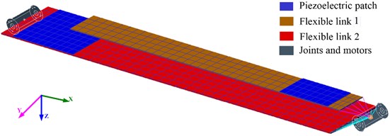
Fig. 1 shows the schematic of a two-link flexible manipulator system. The system consists of two flexible links with bonded piezoelectric actuators and sensors, two revolute joints, and two motors. The first flexible link is clamped on the hub of the shoulder joint. The elbow joint attached at the tip of the first link connects two flexible links together. Under the effect of torques from drive motors, the motion of flexible links is rotational motion about -axes of shoulder joint and elbow joint. Two PZT actuators are perfectly attached to the upper surfaces of the flexible links near the location of each root, respectively. Moreover, two piezofilm sensors are bonded to lower surfaces of the flexible links.
A flexible link of the manipulator system featuring by surface-bonded piezoelectric actuator and sensor is shown in Fig. 2. Subscript denotes the th flexible link, and subscripts , and denote actuator, beam, and sensor, respectively. represents the location of actuator and sensor, measured from the root of the th link, 0.06 m and 0.04 m. The dimensions and mechanical properties of flexible links, piezoelectric actuators and sensors are given in Table 1.
Fig. 1A two-link flexible manipulator system featuring piezoelectric actuators and sensors
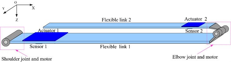
Fig. 2The ith flexible link of the manipulator system
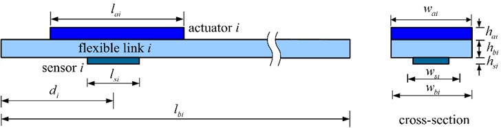
Table 1Dimensional and mechanical properties of the flexible links and piezoelectric actuators and sensors
Dimension (××) | Young’s modulus, (GPa) | Density, (kg/m3) | Piezoelectric constant, (m/V) | |
Link 1 | 0.55×0.08×0.002 | 69 | 2700 | – |
Link 2 | 0.45×0.04×0.0012 | 69 | 2700 | – |
Actuator 1 | 0.1×0.08×0.0008 | 71.4 | 7350 | 200×10-12 |
Actuator 2 | 0.08×0.04×0.0008 | 71.4 | 7350 | 200×10-12 |
Sensor 1 | 0.02×0.02×2.5e-4 | 2.5 | 1800 | 1.5×10⁻¹² |
Sensor 2 | 0.02×0.02×2.5e-4 | 2.5 | 1800 | 1.5×10⁻¹² |
2.2. Sensors and actuators
Fig. 3 is a schematic of the vibration control. It is assumed that the piezofilm sensors are thin with respect to the flexible links, hence the strain in each of them is regarded as uniform over thickness. The piezoelectric sensor can be treated as a parallel plate capacitor, and the charge stored across the electrodes of the capacitor can be expressed as:
where and are the width and length of the sensor, and are elastic modulus and piezoelectric constant of the sensor. is the strain component along the sensor length direction.
Assuming the value of to be average over the piezofilm sensor length, the voltage generated by the sensor can be rewritten as:
Because the piezoelectric sensor has very high output impedance, the output of the sensor is passed through a charge amplifier. Then, the output voltage of the charge amplifier is defined as:
where is the capacitance of the amplifier.
Fig. 3Schematic of the vibration control
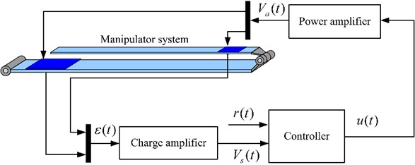
According to Eq. (3), it can be found that the output voltage of the charge amplifier is proportional to the amount of electric charge generated by the sensor. The output signal of the charge amplifier is then fed to the controller designed for the vibration control of the flexible links. The output of controller is amplified by a power amplifier. The final voltage applied to the actuator is the product of and :
where is the voltage applied to the piezoceramic actuator, and is the power amplification factor.
Finally, the rectangular piezoelectric actuator is equivalent to a pair of torques with opposite signs and proportional to :
where is the width of the actuator, and are the thicknesses of the beam and PZT actuator, respectively. and are the Young’s modulus and piezoelectric constant of the PZT actuator.
2.3. Absolute nodal coordinate formulation for the flexible links
Absolute nodal coordinate formulation (ANCF) can be used in the large rotation and deformation analysis of flexible bodies that undergo arbitrary displacements [13]. In this subsection, the ANCF is briefly introduced and the motion equations of flexible links are derived by employing ANCF.
In the absolute nodal frame formulation, the element nodal coordinates are defined in the inertial frame. Here, we define as the vector of element nodal coordinates, and then these nodal coordinates are used with a global shape function . The global shape function has a complete set of rigid body modes that can describe arbitrary rigid body translational and rotational displacements. Therefore, the global position vector of an arbitrary point on the element can be described as:
By differentiating Eq. (6) with respect to time, the absolute velocity vector can be defined. Using the element nodal coordinate and velocity vectors, the kinetic energy and potential energy of the element are given as:
where and are the mass and stiffness matrices of the element, respectively. It is worth noting that, in the absolute coordinate formulation, is a constant matrix and is a highly nonlinear function of the element coordinates and changes over time even in the case of linear elastic problems.
Employing the Lagrange’s equation, one can obtain the equations of motion of the finite element as follows:
where is the vector of generalized nodal force described in the absolute coordinate system. Using the equation of the finite element, connectivity conditions between the finite elements can be imposed and the equations of the elements can be assembled to obtain the equations of motion of flexible links in the multibody system.
Employing the Lagrange multiplier theorem, one can obtain the equations of motion for the constrained manipulator system as follows:
where is the global vector of element nodal coordinates. and are the global mass matrix and stiffness matrix assembled by element mass matrices and element stiffness matrices. is the global force vector described in the absolute coordinate system. and are Jacobian and Lagrange multiplier, respectively.
2.4. Modeling in RecurDyn
The electromechanical model of the two-link manipulator is established and the kinematic process and vibration of the system can be simulated based on the model. RecurDyn, a powerful multibody dynamic analysis software from Korea, is employed here. It combines MBD (Multi Body Dynamics) to analyze the motion of rigid bodies and a nonlinear FEM (Finite Element Method) to analyze the motion, stress, and deformation of flexible bodies. RecurDyn’s solver combines these two components into a single solver. This makes RecurDyn a fast, robust, and reliable solver [26].
The MFBD modeling of the manipulator system can be described as three basic steps. First of all, the finite element models of flexible links are constructed in ANSYS. After that, the finite element models are imported into RecurDyn. Finally, constraints and drivers are added to the model of the flexible manipulator system for kinematics and dynamics simulation.
The finite element models of shoulder link and elbow link are established in ANSYS as shown in Fig. 4. Because the thickness of the piezofilm sensors are much thinner and softer than the flexible links, the influences of the sensors on the system inertia and stiffness properties are neglected in the simulation.
The finite element models are imported into the dynamic simulation software RecurDyn. Two rotational joints and two drivers are included to represent the shoulder and elbow joints, respectively. The flexible links are driven by the drivers, and rotate around axes of the rotational joints. Finally, the dynamic model of the two-links manipulator system is finished with RecurDyn as shown in Fig. 5.
Fig. 4Finite element models of flexible links
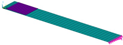
a) Link 1
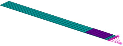
b) Link 2
Fig. 5The multi flexible body dynamical model of the manipulator
3. Fuzzy PID control
The driving torques applied on the joints and subsequent rigid body motion are treated as disturbances to the system which exciting vibrations of the flexible links. To suppress the vibration of the manipulator system, a fuzzy PID controller is developed. The fuzzy PID controller is a hybrid controller combining a conventional PID controller with an adaptive fuzzy controller, and can tune control gains online accommodating to the variation of the system.
3.1. Conventional PID control
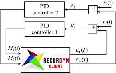
Since PID controller has the advantages of simple structure, high stability and easy design, it has been most widely used in industrial process control. Firstly, a pure PID control is applied to the two-link flexible robot manipulator. The block diagram of active vibration control with two simplified PID controllers is shown in Fig. 6. In the PID controller, the difference between the reference signal and the sensor signal is used as input. The strain, amplified by the charge amplifier, is taken as the sensor signal. The reference input, denoted by , is assigned a zero value:
where is the sensor amplification factor.
Fig. 6Block diagram of active vibration control with a traditional PID controllers
In the PID controller the proportional, integral, and derivative terms are summed to calculate the output of the controller. Defining as the ideal continuous controller output, the final output of a PID controller is given by Eq. (12):
where is error. , and are proportional gain, integral gain, and derivative gain, respectively.
We are concerned with digital control, and for small sampling periods, Eq. (12) may be approximated by a discrete approximation:
where index refers to the time step.
The output of the PID controller is amplified by power amplification, i.e., the applied voltage to the actuator is multiplied by . As mentioned before, the control torques applied to manipulator system is calculated via Eq. (5).
The performance of the PID controller directly depends on an appropriate choice of the PID gains. Table 2 shows the effect of PID parameters on system response. In practice, the values of PID parameters should be settled within a reasonable range.
Table 2Effect of PID parameters on system response
Rise time | Overshoot | Settling time | Steady state error | |
Reduce | Increase | Small change | Reduce | |
Reduce | Increase | Increase | Eliminate | |
Small change | Reduce | Reduce | Small change |
3.2. Fuzzy PID controller design
Conventional PID controllers have proven to be very effective for systems that can be modeled relatively precisely by mathematical equations. However, they have been found to be inefficient in handling systems that are either too complex or too vague to be described by accurate mathematical models. What’s more, the success of the PID controller depends on an appropriate choice of the PID gains and the selection of PID parameters in most cases is not an easy task. It takes a great deal of experience to transform design requirements and objectives to the performance index that will produce the desired performance. To replace experience with analytical tools is very important for complex systems or those without precise descriptions. To determine proper control gains analytically, a fuzzy inference module is designed especially for the conventional PID controller to adjust the PID gains online, according to the error and its change rate. The active vibration control system with fuzzy PID controllers is shown in Fig. 7.
In this subsection, we briefly describe the standard procedure for designing a fuzzy controller, which includes of fuzzification, control rule base establishment, and defuzzification [22, 23].
3.2.1. Fuzzification of input and output variables
The structure of the fuzzy logic system based on the Mamdani inference method includes two inputs and three outputs as shown in Fig. 8. The inputs to the fuzzy inference system are error and the rate of change of the error , and the outputs are increments of PID gains , , and , respectively. Through fuzzy logic knowledge, the fuzzy PID tuners which tune PID parameters (, , ) can be established by using the following equation:
where , , are initial values of fuzzy PID controller gains.
Fig. 7Block diagram of Fuzzy PID control
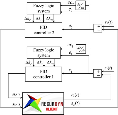
Fig. 8The structure of the fuzzy logic system based on the Mamdani inference method
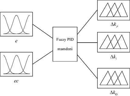
In order to transform the input and output data into proper semantic value, it is necessary to carry out fuzzification of the input and output variables. In this research, the fuzzy range of inputs and outputs is separated into 7 semantic variables, and corresponding fuzzy subsets are [NB, NM, NS, ZO, PS, PM, PB]. Where NB is negative big; NM is negative middle; NS is negative small; ZO is zero; PS is positive small; PM is positive middle; PB is positive big.
The membership functions of two inputs are implemented with seven Gaussian membership functions and scale within the range of [–6, 6]. The membership functions of three outputs are seven triangular membership functions and scale within the range of [–3, 3]. The membership functions are illustrated in Figs. 9 and 10.
3.2.2. Fuzzy control rules
The key to realize self-tuning fuzzy PID control is to find out fuzzy relation between inputs and outputs by using the experience of experts or input-output data. The fuzzy inference rules between inputs and outputs are given as in the form of.
Rule: If is and is , Then is , is and is . Where , , , , (, , , , [NB, NM, NS, ZO, PS, PM, PB]) are linguistic values of inputs and outputs. Table 3 gives out all 49 possible rules.
Fig. 9Membership functions of e and ec
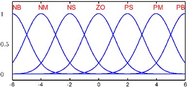
Fig. 10Membership functions of kP, kI and kD
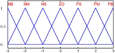
Table 3The fuzzy rule base for PID gains
/ / | ||||||||
NB | NM | NS | ZO | PS | PM | PB | ||
NB | PB/NB/NB | PB/NB/NB | PM/NB/NM | PM/NB/NM | PS/NM/NS | ZO/NM/ZO | ZO/NS/ZO | |
NM | PB/NB/NB | PB/NB/NB | PM/NB/NM | PS/NM/NS | PS/NM/NS | ZO/NS/ZO | NS/ZO/ZO | |
NS | PM/ZO/NB | PM/NS/NM | PM/NM/NS | PS/NM/NS | ZO/NS/ZO | NS/NS/PS | NS/ZO/PS | |
ZO | PM/ZO/NM | PM/NS/NM | PS/NS/NS | ZO/NS/ZO | NS/NS/PS | NM/NS/PM | NM/ZO/PM | |
PS | PS/ZO/NM | PS/ZO/NS | ZO/ZO/ZO | NS/ZO/PS | NS/ZO/PS | NM/ZO/PM | NM/ZO/PB | |
PM | PS/PB/ZO | ZO/PS/ZO | NS/PS/PS | NM/PS/PS | NM/PS/PM | NM/PS/PB | NB/PB/PB | |
PB | ZO/PB/ZO | ZO/PM/ZO | NM/PM/PS | NM/PM/PM | NM/PS/PM | NB/PS/PB | NB/PB/PB | |
3.2.3. Defuzzification
Product-inference rule and center average defuzzzifier are adopted to accomplish fuzzy implication and synthesis calculation respectively. The output of ( and are similar) from the fuzzy inference system is:
where denotes the th fuzzy rule and is the number of rules in the rule base. is any point at which achieves its maximum value, . and are the Gaussian membership function of the input and , respectively:
where and are the corresponding centers and standard deviations of Gauss membership functions, respectively.
4. Simulations and results
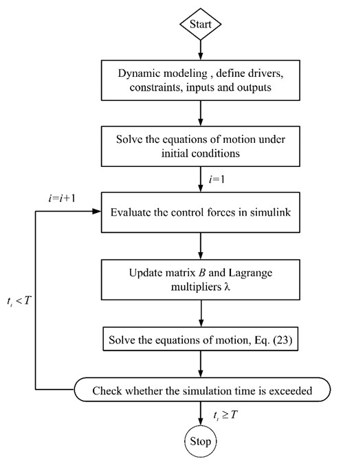
To simulate vibration control of the manipulator system, Matlab/Simulink and RecurDyn are utilized jointly. The procedure of the active vibration control simulation is illustrated in Fig. 11. Firstly, the dynamic model is achieved from RecurDyn as described previously, and the inputs and outputs of model are defined, respectively. The inputs are control torques, and the outputs are strain values at the sensor location. Next, the controllers which calculate control forces are designed in Simulink. Finally, solution is set up and the co-simulation is accomplished step by step.
Fig. 11Flow chart of co-simulation
In this part, the motion processes and dynamic responses of the system are simulated under two different cases: (1) Only the motor of joint 2 drives, joint 1 is locked all the way. Flexible link 2 swings within [0, 3] rad and the variation of angles for joint 1 and joint 2 are shown in Fig. 12(a). (2) Joint 1 uniformly rotates from 0 rad to 23 rad within two seconds and then stops spanning. Joint 2 is locked before joint 1 arrives at desired position. During the span of [2, 3] s, joint 2 uniformly rotates from 0 rad to 3 rad, and then stops. Fig. 12(b) describes the rotating angles of joint 1 and joint 2 for the latter case.
If we take no account of elastic deformation, the motion of the manipulator system becomes multi rigid body movement. The displacement responses of any point for this rigid system are only depending on the large overall motion.
The curves in Figs. 13 and 14 represent the displacements of endpoints for two links. By comparison of the tip displacement curves of flexible system (dotted lines) and rigid system (solid lines), it is found that the disturbances of the driving torques and subsequent rigid body motion can excite vibrations of the flexible links. As pointed out before, there exists the coupling between the large overall motion and elastic vibration during the movement of flexible manipulator system. The stationarity of the flexible manipulator system is deteriorated by unfavorable vibrations. The elastic vibration of each link decays very slowly under only the influence of inherent material damping property. It also suggests that adding active vibration control to manipulator system is necessary.
Fig. 12Rotation angles of joint 1 and joint 2
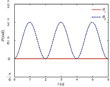
a) Case 1
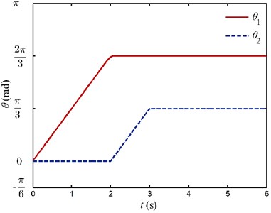
b) Case 2
Fig. 13The motion curves of endpoints for case 1
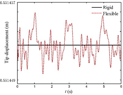
a) Link 1
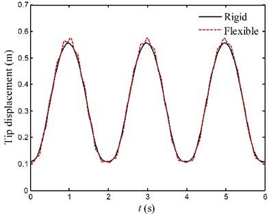
b) Link 2
Fig. 14The motion curves of endpoints for case 2
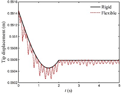
a) Link 1
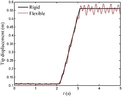
b) Link 2
To verify the effectiveness of the fuzzy PID controller, active vibration control simulations are carried out. In the following simulation, conventional PID control and fuzzy PID control strategies are used for controlling vibrations of the flexible links respectively, for comparison. The sensor and power amplification factors, and are, respectively, taken as 50. The gains of conventional PID controllers are fixed, while the fuzzy PID controllers tune the PID gains online within given ranges. Initial values and adjustable ranges of PID gains for fuzzy PID controllers are listed in Table 4. The saturation blocks are assembled into the controllers to impose upper and lower bounds on the control voltages. On the one hand, the given initial values and adjustable ranges ensure that adjusted gains are within in reasonable ranges. On the other hand, the control voltages are restricted within the limit of actuator voltage by the saturation blocks. Thus, the stability of fuzzy PID controllers can be guaranteed.
Table 4Initial values and adjustable ranges of the gains for the controllers
PID controller 1 | PID controller 2 | Fuzzy PID controller 1 | Fuzzy PID controller 2 | |
Proportional gain | 2.4 | 2.0 | Initial value:2.4 Range: [0.8, 4.0] | Initial value:2.0 Range: [0.8, 3.2] |
Integral gain | 0.6 | 0.4 | Initial value:0.6 Range: [0, 1.2] | Initial value:0.4 Range: [0, 0.8] |
Derivative gain | 0.04 | 0.04 | Initial value:0.04 Range: [0, 0.08] | Initial value:0.04 Range: [0, 0.08] |
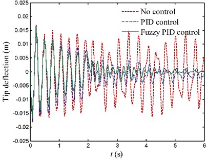
The tip deflection curves of two links under motion process 1 are shown in Fig. 15. In the absence of control, the elastic vibration of each link is really obvious. Although the lowest frequency vibration caused by reciprocating motion is not be effectively suppressed, the higher vibration of each link is distinctly suppressed by active vibration control. This is because the frequency of reciprocating motion is only 0.5 Hz, hence the energy dissipated by the damping effect of piezoelectric actuators is rarely. It is also observed that, the fuzzy PID control method achieves better results than the conventional PID control.
Fig. 15Tip deflection responses of the flexible links for case 1
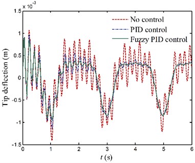
a) Link 1
b) Link 2
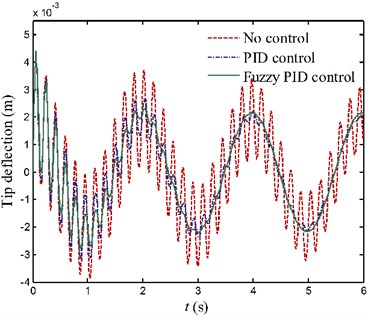
For motion process 2, the vibrations of each link are shown in Fig. 16. The rms (root-mean-square) displacements are calculated and utilized to evaluate the control efficiency of the fuzzy controller. The rms displacement values of link 1 under no control, PID control and fuzzy PID control are 8 mm, 5.1 mm and 4.1 mm, respectively. The rms displacement values of link 2 under no control, PID control and fuzzy PID control are 10.5 mm, 5 mm and 3.9 mm, respectively. Referring at values of the uncontrolled system response, rms displacement values of link 1 and link 2 with PID control are decreased approximately 36 % and 52 %, respectively. Further, the control efficiency can be increased over 10 % through the use of fuzzy controller.
Fig. 16Tip deflection responses of the flexible links for case 2
a) Link 1
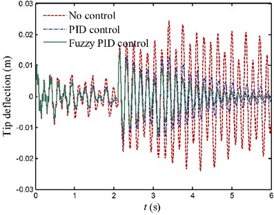
b) Link 2
Fig. 17Applied voltages to the PZT actuators for case 1
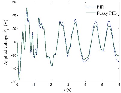
a) Link 1
b) Link 2
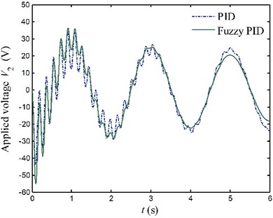
Fig. 18Applied voltages to the PZT actuators for case 2
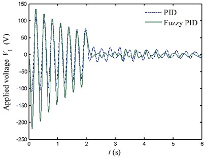
a) Link 1
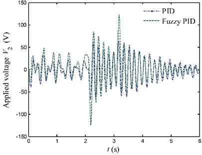
b) Link 2
Figs. 17 and 18 show voltages applied to the PZT actuators. When elastic vibration of flexible link is violent, the control voltages calculated by the fuzzy PID controller are larger compared with the pure PID controller. On the contrary, the control voltages calculated by the fuzzy PID controller are smaller than the pure PID controller while the simulated responses of the system are small. It proves that the fuzzy PID controller tunes control gains online accommodating to the variation of the system. This makes the fuzzy PID controller become a faster controller, and obtain smaller steady error and better control quality.
Through these comparisons, a conclusion can be drawn that the proposed the fuzzy PID controller can improve the performance yielded by a PID controller. By the fuzzy PID control, the unwanted vibration of flexible links is effectively suppressed. The active control significantly decreases the time it will take to an assigned position and improve work efficiency. Hence, the simulation results provide some guidance for studying active vibration control of manipulator systems.
5. Conclusions
This paper focuses on multi flexible body dynamics analysis and active vibration control of a two-link flexible manipulator system. The main contributions of the present paper can be summarized as follows:
1) By using absolute nodal coordinate formulation, the motion equations of the manipulator system are derived. The MFBD model of the system is established, and the electromechanical coupling relations of piezoelectric actuators and sensors are analyzed.
2) The MFBD simulation analysis of the manipulator system has been completed. Tip displacement of each link is compared with those for a rigid manipulator system. It is found that the disturbances of the driving torque and subsequent rigid body motion can excite vibrations of the flexible links. There exists the coupling between large overall motion and elastic vibration during the movement of flexible manipulator system.
3) A fuzzy PID controller, which can tune the PID gains online, is developed and applied to the manipulator system. The elastic vibration of the flexible links is efficiently suppressed using fuzzy PID control. The performances of fuzzy PID controllers and conventional PID controllers are compared and discussed. Simulation results indicate that the fuzzy PID controller achieves better results than the conventional PID controller. In addition, the control methods described in this paper can be extended to control the vibration of other space manipulator system.
References
-
Shin H. C., Choi S. B. Position control of a two-link flexible manipulator featuring piezoelectric actuator and sensors. Mechatronics, Vol. 11, 2001, p. 707-729.
-
Halim D., Luo X., Trivailo P. M. Decentralized vibration control of a multi-link flexible robotic manipulator using smart piezoelectric transducers. Acta Astronautica, Vol. 104, Issue 1, 2014, p. 186-196.
-
Dwivedy S. K., Eberhard P. Dynamic analysis of flexible manipulators, a literature review. Mechanism and Machine Theory, Vol. 41, Issue 7, 2006, p. 749-777.
-
Abedi E., Nadooshan A. A., Salehi S. Dynamic modeling of tow flexible link manipulators. International Journal of Natural Sciences and Engineering, Vol. 2, 2008, p. 461-467.
-
Hastings G. G., Book W. J. A linear dynamic model for flexible robotic manipulators. IEEE Control Systems Magazine, 1987, p. 61-64.
-
Wang P. K. C., Wei J. D. Vibration in a moving flexible robot arm. Journal of Sound and Vibration, Vol. 116, Issue 1, 1987, p. 149-160.
-
Martins J., Botto M. O., da Costa J. S. Modeling flexible beams for robotic manipulators. Multibody System Dynamic, Vol. 7, Issue 1, 2002, p. 79-100.
-
Chen Z. S., Kong M. X., Liu M., et al. Dynamic modeling and trajectory tracking of parallel manipulator with flexible link. International Journal of Advanced Robotic Systems, Vol. 10, 2013.
-
Bricout J. N., Debus J. C., Micheau P. A finite element model for the dynamic of flexible manipulator. Mechanism and Machine Theory, Vol. 25, Issue 1, 1990, p. 119-128.
-
Theodore R. J., Ghosal A. Comparison of the assumed modes and finite element models for flexible multi-link manipulators. The International Journal of Robotics Research, Vol. 14, Issue 2, 1995, p. 91-111.
-
Chung J., Yoo H. H. Dynamic analysis of a rotating cantilever beam by using the finite element method. Journal of Sound and Vibration, Vol. 249, Issue 1, 2002, p. 147-164.
-
Mohamed Z., Tokhi M. O. Command shaping techniques for vibration control of a flexible robot manipulator. Mechatronics, Vol. 14, 2004, p. 69-90.
-
Shabana A. A. Dynamics of Multibody Systems. Cambridge University Press, 2013.
-
Wang W. J., Lu S. S., Hsu C. F. Experiments on the position control of a one-link flexible robot arm. IEEE Transactions on Robotics and Automation, Vol. 5, Issue 3, 1989, p. 373-377.
-
Meirovitch L., Sharony Y. Optimal vibration control of flexible spacecraft during a minimum-time maneuver. Journal of Optimization Theory and Applications, Vol. 69, Issue 1, 1991, p. 31-54.
-
Shaheed M. H., Tokhi O. Adaptive closed-loop control of a single-link flexible manipulator. Journal of Vibration and Control, Vol. 19, Issue 13, 2013, p. 2068-2080.
-
Kim H. K., Choi S. B., Thompson B. S. Compliant control of a two-link flexible manipulator featuring piezoelectric actuators. Mechanism and Machine Theory, Vol. 36, 2001, p. 411-424.
-
Qiu Z. C., Han J. D., et al. Active vibration control of a flexible beam using a non-collocated acceleration sensor and piezoelectric patch actuator. Journal of Sound and Vibration, Vol. 326, 2009, p. 438-455.
-
Bottega V., Pergher R., Fonseca J. S. O. Simultaneous control and piezoelectric insert optimization for manipulators with flexible link. Journal of the Brazilian Society of Mechanical Sciences and Engineering, Vol. 31, Issue 2, 2009, p. 105-116.
-
Zorić N. D., Simonović A. M., Mitrović Z. S., et al. Free vibration control of smart composite beams using particle swarm optimized self-tuning fuzzy logic controller. Journal of Sound and Vibration, Vol. 333, Issue 21, 2014, p. 5244-5268.
-
Carvajal J., Chen G., Ogmen H. Fuzzy PID controller: design, performance evaluation, and stability analysis. Information Sciences, Vol. 123, Issue 3, 2000, p. 249-270.
-
Ahn K. K., Truong D. Q., Thanh T. Q., et al. Online self-tuning fuzzy proportional-integral-derivative control for hydraulic load simulator. Proceedings of the Institution of Mechanical Engineers, Part I: Journal of Systems and Control Engineering, Vol. 222, Issue 2, 2008, p. 81-95.
-
Zheng J. M., Zhao S. D., Wei S. G. Application of self-tuning fuzzy PID controller for a SRM direct drive volume control hydraulic press. Control Engineering Practice, Vol. 17, Issue 12, 2009, p. 1398-1404.
-
Soyguder S., Karakose M., Alli H. Design and simulation of self-tuning PID-type fuzzy adaptive control for an expert HVAC system. Expert Systems with Applications, Vol. 36, Issue 3, 2009, p. 4566-4573.
-
Li G., Li B., Wu D., et al. Feedback linearization-based self-tuning fuzzy proportional integral derivative control for atmospheric pressure simulator. Proceedings of the Institution of Mechanical Engineers, Part I: Journal of Systems and Control Engineering, Vol. 228, Issue 6, 2014, p. 385-392.
-
FunctionBay, Inc., http://www.recurdyn.com.
About this article
This work was supported by the National Natural Science Foundation of China (No. 11302160) of the second author.
