Abstract
Aiming at the complex electromechanical coupling effect at the joints of RP (rotating parallel) flexible robot, the electromechanical coupling dynamics and vibration response characteristics driven by AC servo motor, as well as the dynamic starting characteristics of the motor are studied. The physical model including electromagnetic and mechanical system coupling is established, and the dynamic model of the whole system is derived based on the overall electromechanical coupling effect and Lagrange Maxwell equation. With the help of Matlab/Simulink, a virtual simulation platform is built to analyze the output speed characteristics of the motor drive end and the motion of the moving base. Finally, through the joint simulation of Matlab/Simulink dynamic simulation model and Adams/controls virtual prototype model, the vibration characteristics of flexible manipulator under electromechanical coupling are obtained. The simulation results show that the electromechanical coupling effect of the motor drive end has a significant impact on the dynamic characteristics of the flexible manipulator. The conclusions obtained are of great value for improving the chiral energy of flexible machinery.
1. Introduction
RP (Rotation Parallel) flexible robot system as a typical electromechanical coupling dynamic system, it is a complex electromechanical coupling relationship between the driving system and the actuator, which generates system excitation through the transmission system [1-3]. As a high-speed and light structure, the system excitation caused by electromechanical coupling effect will be more significant because of its low modal frequency. Therefore, the influence of electromechanical coupling effect in the system should be fully considered when analyzing the dynamic characteristics of flexible manipulator [4].
Taking the permanent magnet AC servo drive motor system as an example, there are many kinds of mechanical and electromagnetic coupling in the whole system [5]. [6] studied the precision transmission system and concluded that the output of the servo drive circuit has harmonic effect, and the output electromagnetic thrust of the motor has multi-order harmonic components, which is easy to excite the system vibration, and the excitation effect is generated through the action of the transmission system, thus affecting the dynamic characteristics of the system. By analyzing the electromechanical coupling characteristics of high-speed and high acceleration drive systems. [7] obtained that for high-speed light structures, the system excitation generated by coupling factors will be more prominent. [8, 9] designed a device to simulate the space flexible manipulator, established the coupling dynamic model of the electrically driven flexible manipulator, and studied the influence of electromechanical coupling effect in mechanical system. [10] studied the nonlinear vibration and stability of flexible robot with load under basic harmonic excitation. [11, 12] analyzed the electromechanical coupling dynamic characteristics of mechanical system in detail, and proposed the theoretical analysis method of electromechanical dynamics to solve this kind of problem. [13] established the electromechanical coupling model of machine tool motor spindle and studied the relationship between current and motor spindle output speed characteristics under electromagnetic torque coupling. In addition, for electromechanical systems with multiple coupling relationships, [14] proposed the basic idea of global coupling analysis and parallel partial coupling analysis for the multiple coupling of electromechanical parameters and electrical parameters of modern large-scale complex electromechanical systems. [15] established the coupling dynamic model of multi flexible link flexible hinge manipulator based on hypothetical modal method and Lagrange equation. According to the characteristics of electromechanical dynamics, [16] proposed a global modeling method of complex electromechanical system based on constraint function recursive group aggregation. [17] studied the change of coupling effect between mechanical structure parameters and electrical parameters with the increase of motor torque. Meanwhile, [18] studied the nonlinear dynamics of the flexible arm with basic linear motion, and discussed the stability of the system under the conditions of considering the main parametric resonance, combine parametric resonance and internal resonance. [19] studied the dynamic characteristics and nonlinearity of the system driven by high-speed permanent magnet. At the same time, [20] studied the electromechanical coupling vibration characteristics of the translational manipulator driven by AC servo motor. [2] constructed the coupling dynamic model of motor drive system and analyzed its vibration response characteristics. [21-24] studied the dynamic characteristics of thin plate structure under parametric excitation and external excitation. [25] studied the dynamic characteristics of flexible beam plate structure under fixed axis rotation and parametric excitation. However, at present, most studies consider the flexible manipulator alone, do not specifically consider the coupling relationship between the driving system and the actuator, and assume that the motion of the moving base connecting the flexible manipulator is uniform and constant. Therefore, in some fields with high precision requirements, the motion fluctuation generated by the system will produce some errors in the vibration characteristic analysis and vibration control of the flexible manipulator [26, 27].
Based on the above research, considering the important influence of complex electromechanical coupling effect on the dynamic characteristics and stability of flexible manipulator, the electromechanical coupling dynamics and vibration response characteristics of flexible robot manipulator driven by AC servo motor are studied. The main technical contributions of the proposed scheme are summarized as follows:
1) Considering the coupling between electromagnetic system and mechanical system, a global electromechanical coupling model is established; and the dynamic equation of mechanical structure is derived by using the electromechanical analysis dynamic method.
2)The virtual simulation platform is constructed based on MATLAB/Simulink, the output speed characteristics of the driving end and the motion characteristics of the moving base are analyzed, and the vibration law of the flexible arm under electromechanical coupling is revealed.
3) It is found that in the state of high-speed motion, the non-stationary process in the starting stage of the motor has a more significant impact on the dynamic characteristics of the end of the flexible arm. In some occasions with high requirements for speed accuracy, the impact of the non-stationary process in the starting stage of the motor should be considered.
2. Electromechanical coupling dynamics analysis of flexible manipulator system
Since the invention of permanent magnet generator and motor in the 18th century, electromechanical coupling in mechanical system has become the object of research and analysis [28, 29]. As a typical complex electromechanical system, there are main coupling factors in the whole system, [30-32]. The output of the driving circuit has harmonic effect, and the output electromagnetic thrust of the motor has multi-order harmonic components, which is easy to excite the system to produce vibration, and then affect the flexible manipulator through the action of the transmission system [33, 34]. In recently years, with the rapid development of flexible robot, the research on the dynamic characteristics of flexible manipulator has attracted the attention of many scholars. In the existing research on the dynamic modeling and dynamic characteristics of the flexible manipulator, the flexible manipulator is usually studied separately without considering the coupling effect between the driving system and the actuator, and it is assumed that the moving base connecting the flexible arm is constant in motion, without considering the motion fluctuation caused by electromechanical coupling. Therefore, should be fully considered in the process of studying the vibration characteristics of the flexible manipulator [35].
Based on the existing industrial RP flexible robot, the structural diagram as shown in Fig. 1.
Fig. 1The structural diagram of RP flexible robot system
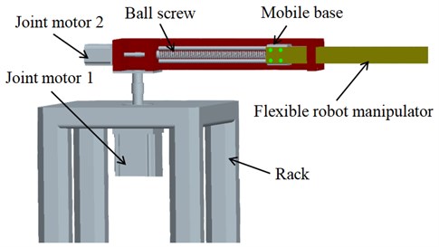
It can be seen from the above Fig. 1 that the flexible robot system includes frame, driving system, roller lead screw, rigid moving base and flexible operating arm. The driving motor 1 can realize the rotary movement of the mechanical structure, the driving motor 2 can realize the translational movement of the roller lead screw, the flexible operating arm is connected with the rigid moving base through bolts, and then the actuator at the end of the operating arm can complete the corresponding operation tasks. Further, according to the law of energy conservation, the energy that drives the whole system of the flexible manipulator comes from electric energy, and the mechanical torque of the mechanical part should be equal to the electromagnetic torque of the permanent magnet synchronous drive motor, so the flexible manipulator system is constructed into a global electromechanical coupling diagram as shown in Fig. 2.
Fig. 2Global electromechanical coupling diagram
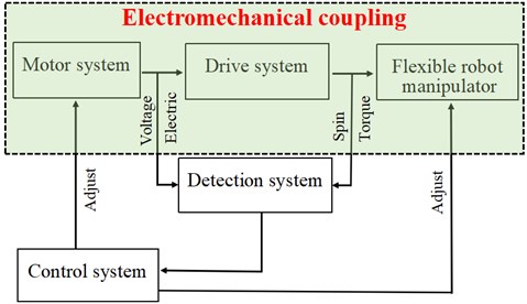
It can be seen from Fig. 2 that the mechanical system, transmission system and execution system are connected through the mutual coupling of electric field and magnetic field. It completes the conversion from electrical signals such as voltage and current to force and torque. It is a typical electromechanical coupling system.
2.1. Physical model of system structure
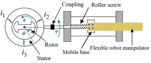
RP flexible robot system is a complex mechanical structure including drive system, transmission system and execution system. The driving system mainly selects permanent magnet AC servo motor, which is composed of stator and rotor. When the stator is connected with three-phase sinusoidal ac, the stator generates a space uniform rotating magnetic field. The stator magnetic field interacts with the rotor magnetic field to generate driving torque, driving the rotor rotation, so as to realize the conversion of electrical energy into mechanical energy. The driving system is composed of roller screw pair, moving guide rail pair and positioning base. The system selects a flexible manipulator. The servo motor is connected with the input end of the roller, and the electric energy is converted into kinetic energy through the rotation of the rotor in the magnetic field, and then drives the moving slider on the roller screw to move, and finally realizes the action of the flexible operation arm. According to the working principle, the drive system, transmission system and execution system are simplified into the physical model shown in Fig. 3.
Fig. 3Global system physical model
2.2. Electromechanical coupling dynamic model
According to the above established system physical model, based on the analysis dynamics method, the electromechanical coupling dynamics model among the driving system, transmission system and execution system of RP flexible robot is established by using Lagrange-Maxwell equation, and the coupling relationship between the output characteristics of synchronous motor and the motion characteristics of positioning base is analyzed according to this model. When mechanical and electromagnetic coupling is established, the following assumptions are made for the driving motor and the flexible operating arm:
1) Ignore core saturation and eddy current loss.
2) The mutual inductance and self-inductance of each phase winding are constant, and the air gap is evenly distributed.
3) The rotor has no damping winding and the permanent magnet has no damping effect.
Firstly, the Lagrange-Maxwell operator can be expressed as:
where represents the sum of the kinetic energy of the drive, transmission and execution system, represents the magnetic field energy in the system, and represents the elastic potential energy in the system.
Secondly, the Lagrange-Maxwell equation can be expressed as:
where represents the dissipation function of the system and represents the non-conservative generalized force of the system.
1) The kinetic energy of the whole mechanical system includes: the rotational kinetic energy of the driving motor, the rotational kinetic energy of the lead screw, the kinetic energy of the moving slider and the kinetic energy of the flexible operating arm, so the sum of the kinetic energy of the system is:
Among them, the first item represents the energy of the driving motor; the second item represents the rotational kinetic energy of the screw; the third item represents the kinetic energy of the moving base and the fourth item represents the kinetic energy of the flexible operating arm. In this analysis system, the end mass is ignored. is the moment of inertia of the motor, is the moment of inertia of the roller lead screw, is the mass of the moving slider, is the rotation angle of the motor, is the density of the flexible operating arm,is the cross-sectional area of the mechanical arm and is the diameter of the roller lead screw.
2) The magnetic field energy in the system includes: the magnetic energy generated by the stator current in the AC permanent magnet synchronous motor; the magnetic energy generated by the rotor permanent magnet and the magnetic energy generated by the interaction between the rotor flux and the stator current. Due to the difference between the three-phase currents 120° and the relatively large number of slots between each pole, it can be considered that the magnetic energy generated by the air gap of the rotor permanent magnet does not change with the rotation of the rotor, that is ( is a constant). Therefore, the sum of magnetic energy in the system is:
where , , respectively represent the self-inductance of three-phase stator winding; represent the mutual inductance of three-phase stator winding, , and represent the three-phase current of motor.
3) The potential energy in the system mainly includes the elastic potential energy when the roller lead screw is twisted and the elastic potential energy of the flexible operating arm. Therefore, the sum of potential energy in the system is:
where represents the torsional stiffness of the roller lead screw, and represents the elastic stiffness of the flexible operating arm.
By introducing Eq. (3), (4) and (5) into Eq. (1), the Lagrange operator of the system can be obtained:
The kinetic energy dissipated in mechanical system mainly includes: resistance dissipation , electric rotor dissipation , friction dissipation between moving slider and roller lead screw:
where , and respectively represent the resistance of three-phase motor, represents the resistance value of rotor and represents the friction coefficient between sliding block and lead screw.
Bring Eq. (3), (4), (5) and (7) into Eq. (1) to obtain the Lagrange equation of the system:
By introducing the above formula into Eq. (2), the voltage equation of stator winding 1 can be obtained:
The voltage equations of stator winding 2 and stator winding 3 as follows:
When the output angle of the motor is taken as the research object in generalized coordinates, the vibration displacement equation of the flexible manipulator can be obtained.
According to Eq. (6):
Bring the above formula into Eq. (2) to obtain the vibration displacement equation of the flexible manipulator in the system:
Similarly, when the displacement of the flexible manipulator is selected as the research object in generalized coordinates, the following can be obtained:
In summary, the global electromechanical coupling dynamic equations of the system can be obtained by combining Eq. (9), (10), (11), (13) and (14):
From the above formula, it can be concluded that there is a coupling phenomenon between the mechanical structure parameters of the AC permanent magnet servo motor such as current, and motor angle and the vibration displacement of the flexible operating arm. With the change of input parameters of AC permanent magnet servo motor, the vibration displacement parameters of flexible manipulator also change, which has a certain impact on the operation accuracy of end effector. Therefore, the theoretical derivation of the global electromechanical coupling based on the above system has an important significance for exploring the vibration mechanism of the flexible arm, the optimal design of the mechanism and improving the positioning accuracy of the system.
3. Establishment of system global electromechanical coupling model and design of virtual simulation platform
3.1. Composition of flexible manipulator system experiment object
Considering that the global electromechanical coupling dynamic model of the above system is a set of nonlinear differential equations, it is difficult to obtain an accurate solution. Therefore, based on the determined global electromechanical coupling dynamic model of the system, a virtual simulation platform of the manipulator system will be built with the help of MATLAB /Simulink for numerical example analysis. The parameters of each mechanical component are established first.
(1) In order to meet the characteristics of high strength and light weight of flexible manipulator. The experimental system uses epoxy fiber board as the flexible manipulator, which has greater stiffness and lighter weight than aluminum. The physical parameters of epoxy resin fiberboard are shown in Table 1.
Table 1Physical parameters of the flexible manipulator
Material | Length / mm | Width / mm | Thickness / mm | Density / kg.m3 | Elastic modulus / Gpa | Poisson’s ratio |
Epoxy Resin | 350 | 50 | 5 | 2030 | 25.24 | 0.30 |
(2) The flexible manipulator driving subsystem adopts the most widely used permanent magnet AC servo motor, its model is MHNJ042GIU, and the motor can detect the operation of each driving motor by relying on its own encoder. Specific physical parameters are shown in Table 2.
Table 2Physical parameters of permanent magnet synchronous AC servo motor
Model | Rated power | Rated torque | Rated speed | Maximum speed | Rotor inertia | Encoder |
MHMJ042GIU | 400 | 1.3 | 3000 | 5000 | 0.67 | 20 bit |
(3) The transmission system is a important component connecting the drive system and the execution system. In this experimental system, the ball screw pair produced by Taiwan TBI company is used, and its main performance parameters are shown in Table 3.
Table 3Physical parameters of ball screw pair
Model | TBI external diameter / mm | Lead / mm | Nut diameter / mm | Nut length / mm | Dynamic load / kgf |
SFS1610 | 15 | 10 | 28 | 47 | 839 |
Fig. 4Flexible manipulator experimental platform
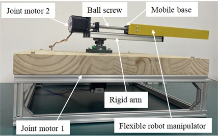
Based on the determination of the parameters of the above parts, finally the RP flexible manipulator experimental platform is built as shown in Fig. 4 (Nanjing Xiaozhuang University, Department of Robotic Engineering, Key Laboratory of Intelligent Robots). The flexible operating arm is fixedly connected to the moving slider of the roller lead screw through bolts. Under the action of the driving torque of AC permanent magnet synchronous motor 1 and 2, the roller lead screw and the moving slider can realize rotation and translation movement, and then drive the flexible operating arm fixed on the moving slider to complete the specified operation.
3.2. Motion characteristic under electromechanical coupling effects
By solving the above Eq. (15), the output characteristics of the AC permanent magnet synchronous motor and the moving slider in the flexible manipulator system can be obtained, and then the output characteristics of the moving base can be taken as the input, so as to obtain the dynamic characteristics of the flexible manipulator in the form of electromechanical coupling. In order to achieve the above purpose, this paper will use the modeling method of the combination of module connection and programming, and build the virtual simulation experimental platform of RP flexible manipulator with the help of MATLAB / Simulink, carry out dynamic simulation analysis on the coupling relationship in the mechanical structure, and study the motion speed characteristics between the driving motor and the moving slider base. The Simulink simulation model is shown in Fig. 5.
Fig. 5Simulink model of system global virtual simulation under electromechanical coupling
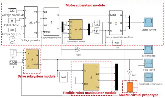
The specific process of the virtual simulation platform is as follows: firstly, the output speed and output torque of the drive motor are solved by the drive subsystem module, and then imported into the drive subsystem module to solve the speed and acceleration of the slider base, finally, the dynamic characteristics and output characteristics of the flexible manipulator in the form of electromagnetic torque direct coupling can be obtained by importing into the flexible manipulator subsystem module.
3.3. Motor output speed characteristics
When studying the speed characteristics of drive motor, the frequency of the power supply is set as = 30 Hz, 40 Hz and 50 Hz respectively. According to the calculation formula:
The output speeds of permanent magnet synchronous motor can be calculated as 450 r/min, 600 r/min and 750 r/min respectively. Where, represents the stator voltage frequency of the permanent magnet synchronous motor, represents the pole pairs of the permanent magnet synchronous motor andrepresents the output speed of the permanent magnet synchronous motor.
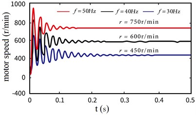
According to the Simulink dynamic coupling simulation model built above, when the three-phase voltage frequency of the motor is set as 30 Hz, 40 Hz and 50 Hz respectively, the output speed curve of the synchronous motor can be obtained, as shown in Fig. 6.
It can be seen from Fig. 6 that the output speed of the drive motor obtained from the virtual simulation model fluctuated significantly at the initial stage, and then gradually tended to rotate at 450 r/min, 600 r/min, and 750 r/min, which is the same as the theoretical calculation results of the above Eq. (20), thus verifying the rationality of the virtual simulation model built in this section. At the same time, it can be seen that the electromechanical coupling in the system is mainly manifested in the fluctuation of motor speed during the non-stationary phase of the starting time of the drive motor.
Fig. 6The output speed (f= 30 Hz, 40 Hz, 50 Hz)
3.4. Speed characteristics of mobile base
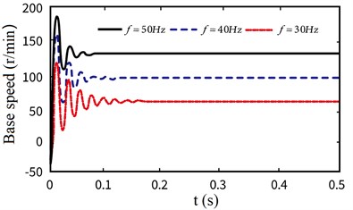
According to the above discussion, it can be seen that there are obvious fluctuations in the output characteristics of the drive motor, which is bound to be transmitted to the flexible arm through the transmission system, and then have a certain impact on the operation accuracy of the end effector. According to the Simulink model of the system established in Fig. 5, similarly, the speed characteristic curve of the moving base under the set voltage and frequency can be obtained, as shown in Fig. 7.
As shown in Fig. 7, when the frequency of the drive motor is set to 30 Hz, 40 Hz and 50 Hz respectively, the speed of the corresponding mobile base is 75 mm/s, 100 mm/s and 125 mm/s. At the same time, it is also found that in the initial stage, due to the obvious vibration of the speed of the drive motor, the speed of the moving base also has an obvious fluctuation and then gradually tends to a stable state.
Fig. 7The velocity characteristic (f= 30 Hz, 40 Hz, 50 Hz)
3.5. Vibration characteristics of flexible arm
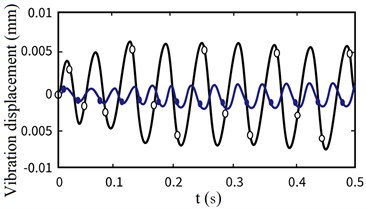
Also based on the virtual simulation platform of the global electromechanical coupling model of the system established in Fig. 5, taking the three-phase stator voltage frequency of AC permanent magnet synchronous motor 30 Hz as an example, the first three-order modal response displacement curves of the flexible operating arm considering the non-stationary in the start-up stage and not considering the non-stationary in the start-up stage are numerically simulated, as shown in Fig. 8.
Fig. 8Displacement curve of under global electromechanical coupling effect and ideal start (f= 30 Hz) (black line – considering the non-stationary process, blue line – not considering the non-stationary process)
a) Vibration displacement (First order)
b) Vibration displacement (Second order)
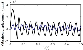
c) Vibration displacement (Third order)
From Fig. 8, we can find that the non-stationary factors in the motor starting stage have a great impact on the first three orders of vibration displacement at the end of the flexible arm, and the lower the modal order is, the greater the amplitude of vibration displacement is. On the contrary, the non-stationary factors have a small impact on the amplitude of vibration displacement, and gradually tend to be stable.
As shown in Fig. 8, the vibration displacement curves of the first three modes at the end of the flexible manipulator under the above two startup states are described respectively. It can be seen from the Fig. 8 that the non-stationary process of permanent magnet motor in the starting stage has an obvious impact on the dynamic characteristics of flexible arm, that is, the increase of vibration displacement amplitude.
Fig. 9The variation of flexible arm end (f= 30 Hz, 40 Hz, 50 Hz)
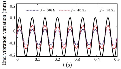
In order to deeply analyze the unstable process of the motor in the starting phase and its impact on the vibration at the end of the flexible arm, we first set the voltage change frequency of the AC permanent magnet motor, which is 30 Hz, 40 Hz and 50 Hz respectively. Under various operating frequencies, we comprehensively consider the impact of the non-stationary factors in the motor starting phase on the elastic vibration at the end of the flexible arm, As shown in Fig. 9, the variation of the end vibration of the flexible manipulator under different operating frequencies is obtained.
It can be seen from the above Fig. 9 that there are differences in the vibration displacement of the end of the flexible manipulator under different target speeds, that is, with the gradual increase of the speed of the drive motor, the amplitude of the end vibration displacement increases gradually, but the frequency is basically constant. It shows that the non-stationary factors in the starting phase of the motor have a greater impact on the vibration of the end of the flexible manipulator at a higher speed. Therefore, when some operations require high accuracy, it is necessary to consider the influence of non-stationary factors on the positioning accuracy of the end effector of the manipulator.
After the above research and analysis, it is shown that the output speed of the drive motor and the moving speed of the moving base in the system have fluctuated to a certain extent under the influence of electromechanical coupling factors, and these fluctuations are bound to have a corresponding impact on the vibration characteristics of the flexible manipulator. Therefore, based on MATLAB/Simulink and ADAMS/Controls, the vibration displacement of flexible manipulator at different motion speeds is explored.
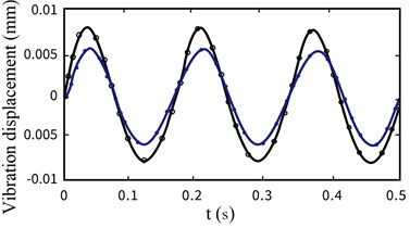
By setting different power frequency in Simulink, the working frequency of the flexible manipulator can be changed, so that its motion speed is different. Therefore, according to the above research, it can be concluded that the mechanical system at this time has motion fluctuations, but the speed of the given moving base is ideal and stable during the ADAMS prototype test without motion fluctuations, so the comparison curve as shown in Fig. 10 is obtained.
Fig. 10Comparison curve between Simulink co-simulation experiment and ADAMS prototype (black line – Simulink co-simulation experiment, red line – ADAMS prototype experiment)
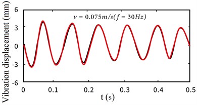
a) Vibration displacement ( 30 Hz)
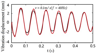
b) Vibration displacement ( 40 Hz)
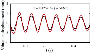
c) Vibration displacement ( 50 Hz)
From the above experimental results, it can be seen that there is the same trend in the case of electromechanical coupling and non-coupling, but the response amplitude is larger. With the faster the mobile base moves, the difference between the vibration displacement of the flexible manipulator in the two cases is more and more obvious. It is further proved that the non-stationary process of the driving motor in the starting phase has more obvious influence on the vibration characteristics of the end of the flexible manipulator at high speed.
4. Conclusions
Taking the electromechanical coupling phenomenon between RP type flexible robot systems as the main research object, by considering the mutual coupling phenomenon between the electromagnetic control system and the mechanical system.
1) The coupling model of machinery and electromagnetism is constructed, and the dynamic equation expression of mechanical system under electromechanical coupling effect is given.
2) Based on MATLAB/Simulink, a virtual simulation platform is established. The motion speed of the driving motor and the motion speed characteristics of the moving slider base are analyzed, and the vibration characteristics of the flexible manipulator under the electromechanical coupling effect are obtained.
3) Experimental results: under the condition of high-speed motion, the coupling effect between machinery and electromagnetic has more obvious influence on the vibration characteristics of the flexible arm end during the non-stationary process of the motor starting phase. That is, with the gradual increase of the speed of the drive motor, the amplitude of the end vibration displacement also gradually increases.
Therefore, in some occasions that require high motion accuracy, more attention should be paid to the negative impact of the non-stationary process of the drive motor in the starting phase. Through the analysis of electromechanical coupling phenomenon between systems, it provides a theoretical basis for studying the vibration characteristics detection of flexible arm under electromechanical coupling.
References
-
S. Wang et al., “Review on modeling theory and control method of flexible manipulator,” Robotics, Vol. 24, No. 1, pp. 86–91, 2004.
-
Y. F. Liu, W. Li, X. F. Yang, Y. Q. Wang, M. B. Fan, and G. Ye, “Coupled dynamic model and vibration responses characteristic of a motor-driven flexible manipulator system,” Mechanical Sciences, Vol. 6, No. 2, pp. 235–244, Oct. 2015, https://doi.org/10.5194/ms-6-235-2015
-
Z.-C. Qiu, “Adaptive nonlinear vibration control of a Cartesian flexible manipulator driven by a ballscrew mechanism,” Mechanical Systems and Signal Processing, Vol. 30, No. 2, pp. 248–266, Jul. 2012, https://doi.org/10.1016/j.ymssp.2012.01.002
-
S. K. Dwivedy and P. Eberhard, “Dynamic analysis of flexible manipulators, a literature review,” Mechanism and Machine Theory, Vol. 41, No. 7, pp. 749–777, Jul. 2006, https://doi.org/10.1016/j.mechmachtheory.2006.01.014
-
M. Östring, S. Gunnarsson, and M. Norrlöf, “Closed-loop identification of an industrial robot containing flexibilities,” Control Engineering Practice, Vol. 11, No. 3, pp. 291–300, Mar. 2003, https://doi.org/10.1016/s0967-0661(02)00114-4
-
T. Kosaki and M. Sano, “Control of a parallel manipulator driven by pneumatic muscle actuators based on a hysteresis model,” Journal of Environment and Engineering, Vol. 6, No. 2, pp. 316–327, 2011, https://doi.org/10.1299/jee.6.316
-
H. Jahanabadi, M. Mailah, M. Z. Md Zain, and H. M. Hooi, “Active force with fuzzy logic control of a two-link arm driven by pneumatic artificial muscles,” Journal of Bionic Engineering, Vol. 8, No. 4, pp. 474–484, Dec. 2011, https://doi.org/10.1016/s1672-6529(11)60053-x
-
Z.-C. Qiu, M.-L. Shi, B. Wang, and Z.-W. Xie, “Genetic algorithm based active vibration control for a moving flexible smart beam driven by a pneumatic rod cylinder,” Journal of Sound and Vibration, Vol. 331, No. 10, pp. 2233–2256, May 2012, https://doi.org/10.1016/j.jsv.2012.01.010
-
M. N. Nguyen, D. T. Tran, and K. K. Ahn, “Robust position and vibration control of an electrohydraulic series elastic manipulator against disturbance generated by a variable stiffness actuator,” Mechatronics, Vol. 52, No. 6, pp. 22–35, Jun. 2018, https://doi.org/10.1016/j.mechatronics.2018.04.004
-
B. Pratiher and S. K. Dwivedy, “Non-linear dynamics of a flexible single link Cartesian manipulator,” International Journal of Non-Linear Mechanics, Vol. 42, No. 9, pp. 1062–1073, Nov. 2007, https://doi.org/10.1016/j.ijnonlinmec.2007.06.001
-
R. Chen, D. Qin, and C. Liu, “Dynamic modelling and dynamic characteristics of wind turbine transmission gearbox-generator system electromechanical-rigid-flexible coupling,” Alexandria Engineering Journal, Vol. 42, No. 9, p. 1062, Oct. 2022, https://doi.org/10.1016/j.aej.2022.10.036
-
X. Yang, W. Zhao, Hui Liu, Lei Wang, and Tao Liang, “Modeling and analysis of the variation facts of dynamic characteristics of the feed system,” in 2013 IEEE International Symposium on Assembly and Manufacturing (ISAM), pp. 362–364, Jul. 2013, https://doi.org/10.1109/isam.2013.6643479
-
J. Chen, R. Zhu, W. Chen, M. Li, X. Yin, and G. Dai, “Nonlinear dynamic modeling and analysis of helical gear system with time-varying backlash caused by mixed modification,” Nonlinear Dynamics, Vol. 243, No. 12, pp. 1–20, Sep. 2022, https://doi.org/10.1007/s11071-022-07872-y
-
S. Zhou, Y. Zhou, Y. Li, Y. Chen, and Z. Ren, “Dynamic characteristics analysis of gear system with coupled thermal-elasto-hydrodynamic-nonlinear effect,” International Journal of Bifurcation and Chaos, Vol. 32, No. 1, pp. 1–5, Jan. 2022, https://doi.org/10.1142/s0218127422500092
-
X. Liu, Y. Yang, and J. Zhang, “Effects of tooth-crack-induced mesh stiffness on fault signals of a planetary gear train,” Procedia Computer Science, Vol. 109, No. 4, pp. 785–792, 2017, https://doi.org/10.1016/j.procs.2017.05.324
-
Y. Zhu, Y. Chen, P. Huray, and X. Dong, “Application of a 2D-CFDTD algorithm to the analysis of photonic crystal fibers (PCFs),” Microwave and Optical Technology Letters, Vol. 35, No. 1, pp. 10–14, Oct. 2002, https://doi.org/10.1002/mop.10502
-
H. Ma, R. Feng, X. Pang, R. Song, and B. Wen, “Effects of tooth crack on vibration responses of a profile shifted gear rotor system,” Journal of Mechanical Science and Technology, Vol. 29, No. 10, pp. 4093–4104, Oct. 2015, https://doi.org/10.1007/s12206-015-0903-6
-
S. K. Dwivedy and R. C. Kar, “Simultaneous combination and 1:3:5 internal resonances in a parametrically excited beam-mass system,” International Journal of Non-Linear Mechanics, Vol. 38, No. 4, pp. 585–596, Jun. 2003, https://doi.org/10.1016/s0020-7462(01)00117-2
-
J. Ju, W. Li, Y. Wang, M. Fan, and X. Yang, “Dynamics and nonlinear feedback control for torsional vibration bifurcation in main transmission system of scraper conveyor direct-driven by high-power PMSM,” Nonlinear Dynamics, Vol. 93, No. 2, pp. 307–321, Jul. 2018, https://doi.org/10.1007/s11071-018-4193-2
-
F. Tang, S. L. Huang, X. L. Hu, and J. T. Wang, “Electro-mechanical coupling characteristics of pzt for sensor and actuator application,” International Journal of Modern Physics B, Vol. 13, No. 29n31, pp. 3823–3826, Dec. 1999, https://doi.org/10.1142/s0217979299003994
-
Y. Arai and T. Yamashita, “Study on seismic response of large-span cantilevered roofs considering vibration characteristics of main structures,” Journal of Structural and Construction Engineering (Transactions of AIJ), Vol. 84, No. 762, pp. 1073–1080, 2019, https://doi.org/10.3130/aijs.84.1073
-
R. Chen, D. Qin, Y. Yi, C. Liu, and J. Shi, “Dynamic characteristics of electromechanical coupling of wind turbine drive system under multi‐source excitation,” Wind Energy, Vol. 25, No. 3, pp. 391–418, Mar. 2022, https://doi.org/10.1002/we.2678
-
S. B. Li and W. Zhang, “Global bifurcations and multi-pulse chaotic dynamics of rectangular thin plate with one-to-one internal resonance,” Applied Mathematics and Mechanics, Vol. 33, No. 9, pp. 1115–1128, 2012, https://doi.org/10.3879/j.issn.1000-0887.2012.09.002
-
X. Guo, W. Zhang, and M. Yao, “Multi-pulse orbits and chaotic dynamics of a composite laminated rectangular plate,” Acta Mechanica Solida Sinica, Vol. 24, No. 5, pp. 383–398, Oct. 2011, https://doi.org/10.1016/s0894-9166(11)60039-6
-
K. Wei, W. Zhang, P. Xia, and Y. Liu, “Nonlinear dynamics of an electrorheological sandwich beam with rotary oscillation,” Journal of Applied Mathematics, Vol. 2012, No. 6, pp. 1–17, 2012, https://doi.org/10.1155/2012/659872
-
W. Zhang, Z. Wen, Y. Ye, and S. Zhou, “Structural mechanics analysis of bolt joint of rigid flexible coupling manipulator,” Journal of Measurements in Engineering, Vol. 10, No. 2, pp. 93–104, Jun. 2022, https://doi.org/10.21595/jme.2022.22688
-
S. S. Ge, T. H. Lee, and J. Q. Gong, “A robust distributed controller of a single-link SCARA/Cartesian smart materials robot,” Mechatronics, Vol. 9, No. 1, pp. 65–93, Feb. 1999, https://doi.org/10.1016/s0957-4158(98)00037-3
-
F. W. Liou, A. G. Erdman, and C. S. Lin, “Dynamic analysis of a motor-gear-mechanism system,” Mechanism and Machine Theory, Vol. 26, No. 3, pp. 239–252, Jan. 1991, https://doi.org/10.1016/0094-114x(91)90066-d
-
A. Smaili, M. Kopparapu, and M. Sannah, “Elastodynamic response of a d.c motor driven flexible mechanism system with compliant drive train components during start-up,” Mechanism and Machine Theory, Vol. 31, No. 5, pp. 659–672, Jul. 1996, https://doi.org/10.1016/0094-114x(95)00094-f
-
H. Tourajizadeh and M. H. Korayem, “Optimal regulation of a cable suspended robot equipped with cable interfering avoidance controller,” Advanced Robotics, Vol. 30, No. 19, pp. 1273–1287, Oct. 2016, https://doi.org/10.1080/01691864.2016.1198719
-
M. H. Korayem, H. N. Rahimi, and A. Nikoobin, “Mathematical modeling and trajectory planning of mobile manipulators with flexible links and joints,” Applied Mathematical Modelling, Vol. 36, No. 7, pp. 3229–3244, Jul. 2012, https://doi.org/10.1016/j.apm.2011.10.002
-
W. Zhang, Z. Wen, Z. You, and X. Ye, “Analysis of vibration characteristics of rotating parallel flexible manipulator considering joint elastic constraints,” Journal of Vibroengineering, Vol. 24, No. 7, pp. 1–14, Jun. 2022, https://doi.org/10.21595/jve.2022.22478
-
Y. Liu, W. Li, Y. Wang, X. Yang, and J. Ju, “Dynamic model and vibration power flow of a rigid-flexible coupling and harmonic-disturbance exciting system for flexible robotic manipulator with elastic joints,” Shock and Vibration, Vol. 2015, No. 6, pp. 1–10, 2015, https://doi.org/10.1155/2015/541057
-
Z.-C. Qiu, Y. Yang, and X.-M. Zhang, “Reinforcement learning vibration control of a multi-flexible beam coupling system,” Aerospace Science and Technology, Vol. 129, No. 15, p. 107801, Oct. 2022, https://doi.org/10.1016/j.ast.2022.107801
-
S. Liu, H. Ai, B. Sun, S. Li, and Z. Meng, “Bifurcation and chaos of electromechanical coupling main drive system with strongly nonlinear characteristic in mill,” Chaos, Solitons and Fractals, Vol. 98, No. 3, pp. 101–108, May 2017, https://doi.org/10.1016/j.chaos.2017.03.013
About this article

This work was supported by the National Natural Science Foundation of China (61772247), Key projects of Natural Science Foundation of Zhejiang Province (LZ21F020003), the National Natural Science Foundation of Zhejiang Province (LY20E050002, LY18F030001) and Nanjing Xiaozhuang College Talent Fund (2020 NXY14).
The datasets generated during and/or analyzed during the current study are available from the corresponding author on reasonable request.
The authors declare that they have no conflict of interest.
