Abstract
The residual vibration is a very universal problem in flexible manipulators which are widely used in robot technology. This paper focuses on the soft measurement of the vibration signals for a translational flexible-link manipulator (TFLM) system. A vibration observer based on the improved Luenberger observer, which only requires the practical measurement values of the boundary positions, is designed to obtain the vibration signals of the TFLM. The main contribution of the vibration observer is its ability to simplify system structure and get the vibration signals of any point of the TFLM which is unrealistic by infinite sensors in practice. Furthermore, the improved part of the Luenberger observer is the added feedback coefficients for the tip vibration signals which can correct the observed mode and reduce the observation error markedly. And according to the stable conditions of observer, the added feedback coefficients are designed by Lyapunov technique and multiple population genetic algorithms (MPGA). Finally, the efficiency of the designed vibration observer is verified by combined-simulation.
1. Introduction
With the high-precision and high-speed development of robot’s technology, the requirements for the mechanical arm are increasingly. Compared with the rigid manipulators, the flexible-link manipulator has numerous advantages, such as smaller damping, higher speed and larger load. As a consequence, it has increasingly applied in many engineering fields such as precision assembly [1], modern manufacturing [2, 3], medical equipment [4], space equipment [5]. However, the flexible-link manipulator exhibits long time residual vibrations which are aroused during the positioning and seriously impacts the positioning speed and accurate tracking ability. Because the flexible-link manipulator is essentially an infinite-dimensional distributed-parameter system and the actuators are fewer than its degrees of freedom which means that the flexible-link manipulator system is under-actuated, the residual vibration control for the flexible-link manipulator is rather challenging [6-8].
In order to constitute effective feedback control to suppress the residual vibrations of the translational flexible-link manipulator (TFLM), the vibration signals should be obtained firstly. Currently, the researchers often measure the vibration signals of TFLM by sensors such as accelerometers [9], strain gauges [10], position-sensitive detector (PSD) [11] and so on. Qiu [12] presented a characteristic model based nonlinear golden section adaptive control algorithm for the TFLM system and significantly suppressed the larger amplitude vibration and the lower amplitude vibration. Malki and Misir [13] applied a fuzzy PID controller to the vibration control of the flexible-joint manipulator and verified the effectiveness and robustness of this control method. In [14], an active vibration controller based on fuzzy logic and neural networks for the vibration suppression of the single-link flexible manipulator was proposed and the experimental results showed its feasibility. Unfortunately, because the low stiffness and large deflection of the TFLM, the addition of sensors is bound to affect dynamic characteristics of the system [15]. Thus, many researchers investigate the location configuration, structure optimization of sensors and control mechanism optimization for reducing the influence of sensors on the system. Sun [16] described the validity of piezoelectric materials (PZT) for the vibration suppression of a single-link flexible manipulator and the PSD sensor, which is a kind of disconnection displacement sensor, is applied to obtained the vibration signals of the flexible manipulator. In [17], a novel observer-based robust dynamic feedback tracking controller without velocity measurements was developed to the motion tracking control of flexible-joint robotic manipulators and the number of sensors can be greatly reduced. An optimization problem with genetic algorithms (GA) is formulated in [18], which is aim to optimize the location and size of the sensors on the flexible manipulators. However, in those methods, the influences of sensors on the dynamic characteristics and structural optimization still exist while the sensors are used to obtain the vibration signals. Besides, the residual vibration of the TFLM is often suppressed by adding additional actuators [19, 20]. Due to the position limitation, the sensors can only obtain the residual vibration signals near the actuators which seriously affects the control effect. Furthermore, because the actuators positions should be optimized firstly [11, 16], the vibration signals of any point of the TFLM is indispensable which is unrealistic by infinite sensors.
Fortunately, the Luenberger observer can estimate the internal state variables by the measurable input and output variables which is a kind of method for indirect measurement [21]. Based on this, the vibration signals of the TFLM can be effectively estimated by rational Luenberger observer. In [22], an observer based on partial differential equation (PDE) model was presented to achieve the estimate of the infinite dimensional states for a flexible-link manipulator. Mosayebi [23] developed a nonlinear high gain observer to estimate the elastic degrees of freedom and their time derivatives for flexible-link manipulators. But those observer is only based on the feedback values of the joint angles which is an open-loop observation method for the elastic degrees of freedom and the observation error cannot be solved. Above all, there are two major methods in observer design of the TFLM: one is based on the ordinary differential equation (ODE) models [23-25] and another is based on PDE models [22]. Through comparing these two methods, although the PDE models can describe the TFLM system more precisely, the complicated calculations seriously affect the effect of real-time observation. Then, many researchers apply ODE models to construct observer in practical application. On the other side, because observers are based on the theoretical models, the intrinsic deviations of ODE models, which include the imprecise part caused by mode truncation and the nonlinear part, obviously affect the observation accuracy. Thus, the solutions of observation error should be further analyzed.
Therefore, based on the ODE dynamic model of the TFLM, a vibration observer is constructed in this paper. In this way, the vibration signals of any point on the TFLM can be got with limited sensors. In view of the modal truncation errors of ODE model, the tip vibration signals are fed back to improve the observation precision of the other positions of the TFLM. The design process of the vibration observer gains deals with two parts. The basic part is based on the thought of no deviation Kalman estimator and the part of observation error compensation is designed by Lyapunov technique and multiple population genetic algorithms (MPGA).
The remainder of this paper is organized as follows. The dynamic modeling of TFLM is given in Section 2. The main contribution of this paper is described in Section 3, including the design and analysis of the observer. Section 4 provides the union simulations to illustrate the effectiveness of the proposed control strategy. Finally, conclusions are drawn in Section 5.
2. Dynamic modelling of the TFLM
Schematic diagram of a TFLM system is shown in Fig. 1. During the construction of the dynamic model, assumptions are made as follows: (a) The TFLM is simplified as a Euler-Bernoulli beam and the impact of shear and axial deformation can be neglected. (b) The connection between the TFLM and the slider is pure rigid. (c) The influence of gravity can be neglected.
Fig. 1Schematic diagram of the TFLM system
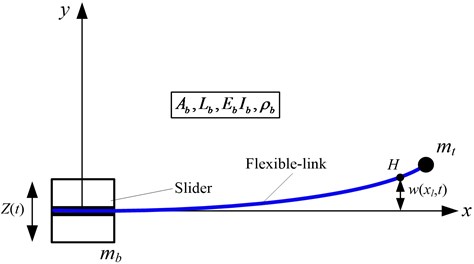
In accordance with the assumed mode methods [24, 25], the axial absolute coordinates of which is a random point on the TFLM can be expressed as:
where is the slider displacement, denotes the elastic deformation of , is the th modal shape, is the modal coordinates. The boundary conditions, which are one end fixed and another end free, formulate the modal shape as follows:
where is constant coefficient which is also determined by the boundary conditions.
Through dynamic analysis of the TFLM, the kinetic energy of the system can be written as:
where is mass of the slider, is mass of the payload. , and are the density, the sectional area and the length of the TFLM, respectively.
Potential energy of the system mainly consider the elastic potential energy caused by the elastic deformation of the TFLM and can be expressed as:
where and are the elastic modulus and moment of inertia of the TFLM, respectively.
The external forces of the TFLM primarily include the driving force and the friction between the slider and the linear guide. The driving force , as the control input of TFLM system, is generated by the motor through a reducer and a ball screw. So the virtual work [26] of the TFLM system is represented by:
where is the friction coefficient between the slider and the linear guide and is the structural damping of the TFLM. According to the second Lagrange equation [27] as follows:
where denotes generalized force which corresponds to generalized coordinates . is Lagrange multiplier and can be expressed as:
By substituting Eq. (1) into Eq. (7) and Lagrange approach, the dynamic model of the TFLM can be deduced which is showed as:
where is the th natural frequency of the TFLM. According to the orthogonality of the modal shape, Eq. (9) can be further simplified as:
By defining , Eq. (8) and Eq. (10) can be converted as:
Taking the state variables as , the system dynamic equation can be transformed into the state space equation whose form is:
where:
3. Observer design
Through the analysis of the observability [28], the TFLM system is completely observable, which meet the existence conditions of a Luenberger observer. By using the dynamic model of the TFLM in Section 2, the vibration observer based on Luenberger observer is constructed, as illustrated in Fig. 2. Where expresses the estimates of tip vibration signals of the TFLM. and are denoted as the estimates of and , where . Then, the estimate of can be expressed as:
Fig. 2Principle diagram of vibration observer
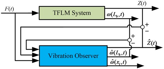
Because the number of modal shapes only affect the complexity of the calculation, the following illustrates the design process of vibration observer by only considering the first-order mode. Vibration observer equation can be written as:
where and are the designed observer gains. and express the observation error of the slider and the tip vibration displacement, respectively.
Firstly, and are directly measured through sensors. Subtracting Eq. (14) from Eq. (12), the error model of vibration observer can be obtained as:
where and represents the observation error of the state variables () and . The designed observer gains of vibration observer compose of two parts: is based on the thought of no deviation Kalman estimator and is designed by the purpose to guarantee the stability of the observer system and minimize observation error of the vibration signals. The form of appears as follow:
where is the positive definite solution of Ricatti equation by defining appropriate and which are positive definite diagonal matrix. The form of Ricatti equation can be written as:
In order to guarantee the stability of the observer system, the Lyapunov function of the error model is defined as:
Differentiating with respect to time yields:
where:
By substituting Eq. (18) into Eq. (19) and combining with Eq. (17), Eq. (19) can be further simplified as:
Because and are symmetric positive definite matrix and is positive definite matrix too, the first item of is obviously less than zero which is shown as:
It can be got form Eq. (21) that only if . Then in order to pledge , Eq. (22) which the coefficients of are satisfied can be obtained:
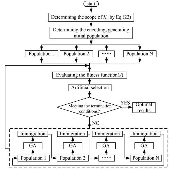
With the above analysis, the designed observer system is asymptotically stable when the observer gains satisfy Eq. (16) and Eq. (22). Because Eq. (22) only determines the range of , the MPGA is adopted to achieve the optimization of . To implement the evolution steps of MPGA, the conventional strategies of selection, crossover, mutation and the unique strategies of immigration, artificial selection are necessary. In the optimization process of , MPGA can search the optimum and change the best individuals in multi-populations by immigration. Then the purpose of cooperative coevolution can be achieved. Artificial selection is added to avoid the outstanding individuals being destroyed by crossover and mutation operation in the population. The procedure of optimizing is shown in Fig. 3.
In order to achieve the purpose of minimizing the observation error, the fitness function () is defined as:
where is the terminal time of simulation. The optimized target is minimize . Termination condition is the retentive generations of the optimal individual which can take full advantages of the knowledge accumulation ability of GA and guarantee convergence towards global optimum.
Fig. 3Flow chart of optimizing Kp
4. Simulation experiment of the TFLM
To illustrate the effectiveness of the designed vibration observer, the physical model of TFLM, which is constructed in ADAMS, is regarded as the controlled object. The material of the TFLM is stainless and relevant physical parameters are listed in Table 1.
The physical model of TFLM consists of two parts: one part is the slider and the support, the other is the flexible manipulator. The two parts are concatenated together by fixed constraints. The vibration signals of any point of the TFLM can be figured out by ADAMS/Flex. The input is defined as the driving force of slider and the outputs are set to the displacements of slider and the desired points of TFLM. Then, the physical model is converted into Simulink subsystem which is used to establish combined-simulation platform.
Table 1Physical parameters of the TFLM
Project | Length / m | Density / kg.m-3 | Sectional area / m2 | Modulus of elasticity / GPa | Slider quality / kg | Payload quality / kg |
Value | 0.635 | 7850 | 2.83e-5 | 197 | 0.5 | 0.2 |
Fig. 4Five times evolutionary process by MPGA
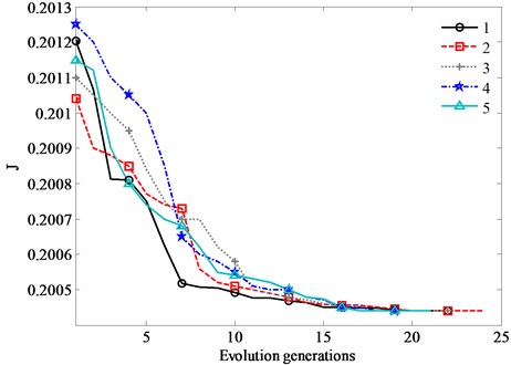
As indicated in [29], the low order modes play a leading role of the vibrations and the higher modes can be neglected in the assumed mode methods. Thus, in order to simplify the computation, only the first-order mode is taken into consideration in the process of optimizing . The total simulation time is 2.5 s and the retentive generations of the optimal individual is 4 which is deemed as the termination condition. The optimization results of is shown in Fig. 4.
In Fig. 4, the optimal values are consistent in five times evolutionary process which means that the evolutionary process of is sufficient by MPGA. Through the above analysis, the optimal observer gains of vibration observer are and .
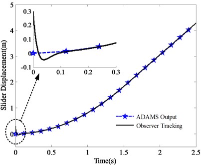
Afterwards, the tracking effect of observer is examined, under the initial state of 0.3 m which is seen as the initial disturbances. The tracking effects of slider displacement () and slider speed () are shown in Figs. 5 and 6.
It is obtained from Figs. 5, 6 that the designed observer can quickly track the slider displacement and speed whether in the uniform acceleration or constant velocity phase. The tracking accuracy of slider displacement and speed is high and the initial disturbances can be quickly eliminated.
Fig. 5Tracking effect of slider displacement
In order to verify the tracking effect of the designed observer for the vibration signals of TFLM, the vibration signals of 0.4 m and 0.5 m are selected to be observered by compared with conventional Luenberger observer. The tracking effects are shown in Figs. 7, 8, where VS indicates the actual vibration signals, CO means the estimation of conventional Luenberger observer and ILO indicates the estimation of improved Luenberger observer.
Fig. 6Tracking effect of slider speed
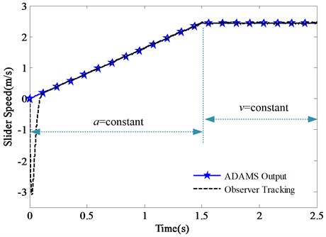
Fig. 7Tracking effect of vibration signals (xl= 0.4 m, xl= 0.5 m)
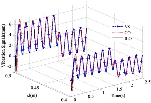
Fig. 8Tracking error of vibration signals (xl= 0.4 m, xl= 0.5 m)
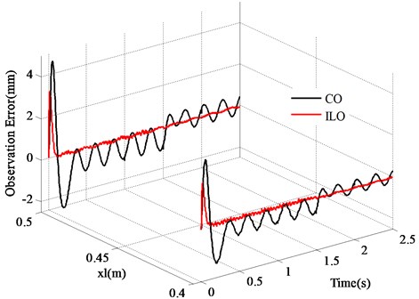
The results shown in Figs. 7, 8 indicate, as expected, that the designed observer is effective. Tracking trend of the vibrations is consistent with the output of ADAMS in a very short period of time whether the designed observer or the conventional Luenberger observer. Although the designed observer is based on the ODE model of the TFLM which is identical with the conventional Luenberger observer, the tracking error of amplitude is well solved after correcting the observed mode by feeding back the tip vibration signals.
5. Conclusions
In this work, a vibration observer based on improved Luenberger observer is proposed to obtain the vibration signals of the TFLM. Then a physical model of the TFLM is established by ADAMS software to verify the effectiveness of the vibration observer. The results demonstrate that the proposed vibration observer has a good observation effect of the vibration signals, meanwhile reduces the observational vibration error remarkably by compared with the conventional Luenberger observer. Through comparing observation results with the ADAMS outputs, the practicability of the designed observer is proved. The results obtained in this paper can be applied for the robot manipulators in such as precision assembly, modern manufacturing, medical equipment, space equipment and has positive effects on motion planning, optimization of actuators positions and residual vibrations control for flexible-link manipulator in future research. Moreover, it has positive significance for the structural optimization and cost reduction in practical application by replacing the sensors.
References
-
Dwivedy S. K., Eberhard P. Dynamic analysis of flexible manipulators, a literature review. Mechanism and Machine Theory, Vol. 41, Issue 7, 2006, p. 749-777.
-
Abe A. Trajectory planning for residual vibration suppression of a two-link rigid-flexible manipulator considering large deformation. Mechanism and Machine Theory, Vol. 44, Issue 9, 2009, p. 1627-1639.
-
Katsura S., Suzuki J., Ohnishi K. Pushing operation by flexible manipulator taking environmental information into account. IEEE Transactions on Industrial Electronics, Vol. 53, Issue 5, 2006, p. 1688-1697.
-
Riviere C. N., Ang W. T., Khosla P. K. Toward active tremor canceling in handheld microsurgical instruments. IEEE Transactions on Robotics and Automation, Vol. 19, Issue 5, 2003, p. 793-800.
-
Gouliaev V. I., Zavrazhina T. V. Dynamics of a flexible multi-link cosmic robot manipulator. Journal of Sound and Vibration, Vol. 243, Issue 4, 2001, p. 641-657.
-
Rahimi H. N., Nazemizadeh M. Dynamic analysis and intelligent control techniques for flexible manipulators: a review. Advanced Robotics, Vol. 28, 2014, p. 63-76.
-
Shan J, Liu H. T., Sun D. Modified input shaping for a rotating single-link flexible manipulator. Journal of Sound and Vibration, Vol. 285, Issue 1, 2005, p. 187-207.
-
Hassan M., Dubay R., Li C., Wang R. Active vibration control of a flexible one-link manipulator using a multivariable predictive controller. Mechatronics, Vol. 7, Issue 6, 2007, p. 311-323.
-
Staufer P., Gattringer H. State estimation on flexible robots using accelerometers and angular rate sensors. Mechatronics, Vol. 22, Issue 8, 2012, p. 1043-1049.
-
Ramos F., Feliu V. New online payload identification for flexible robots. Application to adaptive control. Journal of Sound and Vibration, Vol. 315, Issues 1-2, 2008, p. 34-57.
-
Shan J. J., Liu H. T., Sun D. Slewing and vibration control of a single-link flexible manipulator by positive position feedback (PPF). Mechatronics, Vol. 15, Issue 4, 2005, p. 487-503.
-
Qiu Z. C. Adaptive nonlinear vibration control of a Cartesian flexible manipulator driven by a ball screw mechanism. Journal of Mechanical Systems, Vol. 30, 2012, p. 248-266.
-
Malki H. A., Misir D. Fuzzy PID control of a flexible-joint robot arm with uncertainties from ime-varying loads. IEEE Transactions on Control Systems Technology, Vol. 5, 1997, p. 371-378.
-
Jnifene A., Andrews W. Experimental study on active vibration control of a single-link flexible manipulator using tools of fuzzy logic and neural networks. IEEE Transactions on Instrumentation and Measurement, Vol. 54, Issue 3, 2005, p. 1200-1208.
-
João C. P. R., José S. D. C. Motion planning and actuator specialization in the control of active-flexible link robots. Journal of Sound and Vibration, Vol. 331, 2012, p. 3255-3270.
-
Sun D., Mills J. K., Shan J. J., Tso S. K. A PZT actuator control of a single-link flexible manipulator based on linear velocity feedback and actuator placement. Mechatronics, Vol. 14, Issue 4, 2004, p. 381-401.
-
Chang Y. C., Yen H. M. Robust tracking control for a class of electrically driven flexible-joint robots without velocity measurements. International Journal of Control, Vol. 85, Issue 2, 2012, p. 194-212.
-
Molter A., Da Silveira O. A. A., Fonseca J. S. O., Bottega V. Simultaneous piezoelectric actuator and sensor placement optimization and control design of manipulators with flexible links using SDRE method. Mathematical Problems in Engineering, Vol. 2010, 2010, p. 1-23.
-
Dadfarnia M., Jalili N., Xian B., Dawson D. M. A Lyapunov-based piezoelectric controller for flexible Cartesian robot manipulators. Journal of Dynamic Systems Measurement and Control – Transactions of the ASME, Vol. 126, Issue 2, 2004, p. 347-358.
-
Qiu Z. C., Han J. D., Zhang X. M., Wang Y. C., Wu Z. W. Active vibration control of a flexible beam using a non-collocated acceleration sensor and piezoelectric patch actuator. Journal of Sound and Vibration, Vol. 326, Issues 3-5, 2009, p. 438-455.
-
Kolhe J. P., Shaheed M., Chandar T. S., Talole S. E. Robust control of robot manipulators based on uncertainty and disturbance estimation. International Journal of Robust and Nonlinear Control, Vol. 23, Issue 1, 2013, p. 104-122.
-
Yang H. J., Liu J. K., Lan X. Observer design for a flexible-link manipulator with PDE model. Journal of Sound and Vibration, Vol. 341, 2015, p. 237-245.
-
Mosayebi M., Ghayour M., Sadigh M. J. A nonlinear high gain observer based input-output control of flexible link manipulator. Mechanics Research Communications, Vol. 45, 2012, p. 34-41.
-
Green A., Sasiadek J. Z. Dynamics and trajectory tracking control of a two-link robot manipulator. Journal of Vibration and Control, Vol. 10, Issue 10, 2004, p. 1415-1440.
-
Yang T. W., Xu W.L., Tso S. K. Dynamic modeling based on real-time deflection measurement and compensation control for flexible multi-link manipulators. Dynamics and Control, Vol. 11, Issue 1, 2001, p. 5-24.
-
Vidoni R., Gasparetto A., Giovagnoni M. A method for modeling three-dimensional flexible mechanisms based on an equivalent rigid-link system. Journal of Vibration and Control, Vol. 20, 2014, p. 483-500.
-
Rognant M., Courteille E., Maurine P. A systematic procedure for the elastodynamic modeling and identification of robot manipulators. IEEE Transactions on Robotics, Vol. 26, Issue 6, 2010, p. 1085-1093.
-
Liu K., Sun X. System identification and model reduction for a single-link flexible manipulator. Journal of Sound and Vibration, Vol. 242, Issue 5, 2001, p. 867-891.
-
Kiang C. T., Spowage A., Yoong C. K. Review of control and sensor system of flexible manipulator. Journal of Intelligent and Robotic Systems, Vol. 77, Issue 1, 2015, p. 187-213.
About this article
This research work was partially supported by the National Natural Science Foundation of China (Nos. 51305444 and 51307172), the Doctoral Fund of Ministry of Education under Grants (No. 20120095120013), the Scientific and Technological Project of Jiangsu Province (BY2014028-06), the Jiangsu Provincial Natural Science Foundation of China (BK2012567), the Postgraduate Cultivation and Innovation Project of Jiangsu Province (KYLX_1375), and the Project Funded by the Priority Academic Program Development of Jiangsu Higher Education Institutions (PAPD). The authors would like to thank the editor and the reviewers for their comments and suggestions which have improved the presentation.
Jinyong Ju contributed significantly to the specific design process of the study and wrote the manuscript. Wei Li helped perform the whole analysis with constructive discussions. Yuqiao Wang contributed to the model of the TFLM system with instructional advices. Mengbao Fan contributed to the validation method of the designed vibration observer with guiding suggestions. Xuefeng Yang contributed to the design of the added feedback coefficients for the tip vibration signals with some useful suggestions. Yufei Liu contributed to the optimization of the structure relationship and the manuscript revision.
