Abstract
Cellular phones have not only function to communicate, but also have e-banking, web surfing, music, and entertainment. The performance of the smartphone has improved because of various functions of smartphone, and capacity of battery has also improved gradually. Although smartphone batteries have been improved compared to conventional batteries, the available usage time of a phone’s rechargeable battery is getting shorter because of the demands of various applications. Therefore, we propose a new tubular permanent magnet linear generator that uses a Halbach array, to send a message or emergency call when the battery is discharged. In order to increase the power generation of existing tubular linear generators, we changed the axial-direction permanent magnet array to a Halbach-type array. When using the Halbach array, it is possible to generate a strong magnetic field without additional magnetic material. In this research, we compared the Halbach array that uses axially and radially magnetized permanent magnets with an existing model that uses an axially magnets. We verified improvement in the amount of power generated with no-load analysis through simulation using the Maxwell commercial electromagnetic analysis software.
1. Introduction
A cellular phone is the most commonly used mobile device for transferring information among people. Although battery capacity has improved, the dramatically increased usage of cellular phones makes the battery service time shorter and shorter.
In order to address this problem, an embedded linear generator for a self-rechargeable smartphone has been developed by Park et al. [1]. The linear generator's operation is based on a resonance phenomenon, the electromagnetic force is generated based on Faraday's law, and the smartphone battery is charged by electromagnetic force. In the case of existing smartphone generators [1], the battery usage time generated by walking motion is not enough to power an urgent call because of low efficiency. There are many array types of permanent magnet(PM) in linear generator. The radius direction array was introduced by Ishiyama et al. The PM is placed face-to-face, and there is a mutual repulsion [2]. The axial direction array, which is different than Ishiyama’s array, was introduced by Murphy [3]. A Halbach array is an arrangement of permanent magnets that augments the magnetic field on one side of the array while cancelling the field to nearly zero on the other side. The rotating pattern of the PM (left, up, right, down) is used [4, 5]. In this study, we developed a built-in linear generator system for a smartphone with a Halbach array permanent magnet in order to maximize the power generation with respect to the aforementioned problems. The Halbach array is a sequence that arranges an alternately radially- and axially-magnetized permanent magnets. In this paper, we analyzed Halbach-type magnetic characteristic and compared with conventional axially magnetized permanent magnet. Finite element analysis (FEA) using the commercial software Maxwell (Ver. 16, ANSYS, Southpointe 2600 ANSYS Drive Canonsburg, PA 15317 USA) is performed to simulate the electric generation. The results of the simulation and experiment show that the proposed generation system has enough potential to be considered for practical use.
2. Generation system
2.1. Structure and principle of Halbach array generator
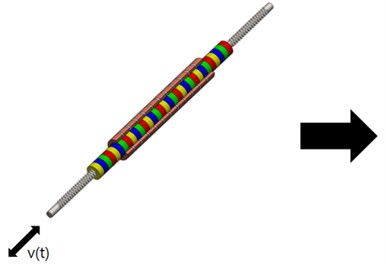
Fig. 1 shows a schematic diagram of a tubular linear generator. A conventional tubular linear generator consists of a slider and stator. The slider consists of axially-magnetized permanent magnets and a pole shoe, which functions as a conductor of the magnetic field.
The stator consists of a coil and coil housing, and a 2-pole 3-phase coil winding. Two springs enable the slider to produce resonance.
Fig. 1Schematic diagram of conventional tubular linear generator
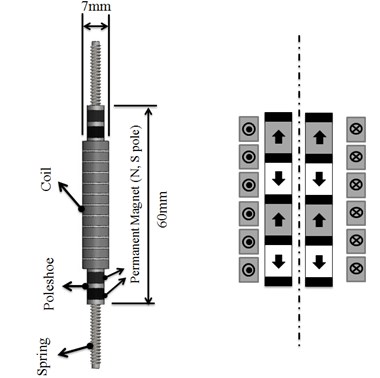
Fig. 2Schematic diagram of tubular linear generator applying Halbach array
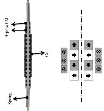
Fig. 2 shows a schematic diagram of a Halbach array tubular linear generator. The Halbach array generator consists of both axial magnetized permanent magnets and radial magnets. One sided magnetic fluxes were introduced by John C. Mallinson [6], and Halbach array was developed by Kaus Halbach [7]. In the case of the Halbach array generator shown in Fig. 3, if the axial and radial permanent magnets were magnetized alternatively, magnetic flux is concentrated in only one direction [8-10] because the opposite direction is offset. Thus, it maximizes the amount of power generation compared to conventional models without the addition of magnetic material [11]. The pole shoe functions as a conductor of the magnetic field to replace the radial magnetized permanent magnet on a conventional generator. The coil winding is formed with a 4-pole 3-phase that is different from the existing generator with the 2-pole 3-phase.
Fig. 3Principle of superposition of Halbach array
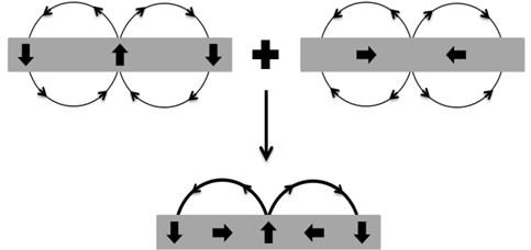
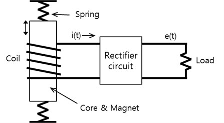
Fig. 4 shows a diagram of the energy conversion principle. The electromotive force is generated at the stator coil terminals as the slider vibrates up and down by the shaking motion and walking motion of the user. The EMF is calculated by using Faraday’s law and can be expressed as follows:
where N is the number of turns per coil, ϕ is the flux passing in each turn in real time t, dz/dt is the slider speed, and z is the distance along the z-direction. So, the electromotive force is proportional to the number of coil windings, the variation of magnetic flux that interlinks the coil winding to the displacement of the slider, and the speed of the slider [12].
Fig. 4Energy conversion diagram
2.2. Analysis of the linear generator and resonance phenomenon
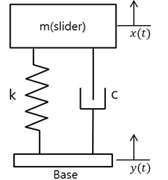
Excitation by the user’s motion produces base excitation. Fig. 5 is a free body diagram for the analysis of base excitation. In Fig. 5, m is the mass of the slider, k is the spring coefficient, and c is the coefficient of damping. The base excitation can be expressed by Eq. (2). y(t) is Ysinωbt, representing the displacement of the base, and the displacement and velocity of the slider are denoted as x(t) and v(t), respectively. The amplitude of x(t) is calculated by using Eq. (3). In Eq. (3), ζ represents the damping ratio of the linear generator. The frequency of walking motion is in the range of 2 to 2.2 Hz [13], and the frequency of shaking motion is in the range of 3.0 to 5 Hz [1].
where ωn is the natural frequency and ωb is the base excitation frequency.
Fig. 5Free body diagram for the analysis of the base excitation
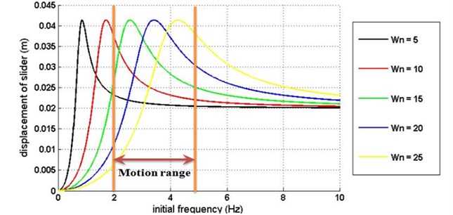
In the case of walking motion, the displacement amplitude of the base excitation is less than 2 cm, which does not create enough displacement for adequate electric generation. To maximize the mechanical energy from the motion, the resonance phenomenon is exploited by matching the motion frequency to the mechanical natural frequency of the generator. It is possible to check the displacement amplitude in accordance with the input frequency by using Eq. (3), as shown in Fig. 6.
According to Fig. 6, the vibration characteristic is different for each natural frequency. In the case of walking or shaking motion (2 to 5 Hz), we confirmed that mechanical resonance occurs when the natural frequency (ωn) is 15 rad/s. Then, we determined the optimal mass of the slider, the coefficient of the spring, and other specifications for sufficient vertical motion using this result.
Fig. 6Displacement amplitude versus input frequency
3. Finite element analysis
In order for the proposed device to be installed inside the smartphone, the overall size of the generation system must be less than 60 mm in length and 7 mm in diameter. Accordingly, the magnetic circuit (e.g., the permanent magnet, pole shoe, and electromagnetic coil) is designed to satisfy the size specification with large electricity generation. In order to validate the change in the number of magnets while meeting the size requirements, we conducted a parameter study using no-load analysis with the commercial electromagnetic analysis software Maxwell to determine the back electromotive force with no load simulation when the ideal current is zero.
Table 1 shows the specifications for the linear generator. We determined the specifications based on the parameter study. After determining the diameter of the coil that can accommodate the allowable current in a limited space, and determining the required number of windings, the winding resistance is determined according to number of coil windings.
Table 1Specifications of the linear generator
Quantity | Value |
Capacitance | 200 µF |
Number of coil windings | 1044 turns |
Coil winding resistance | 225 Ω |
We assumed that the walking speed is 5 km/h, the peak-to-peak size of the displacement due to walking is about 3 cm, the frequency is 2 Hz, and the operational shaking frequency range is 3 to 5 Hz. We used a frequency of shaking motion of 3.3 Hz to compare with the generating characteristics of a conventional model. Dynamic finite-element analysis using the nonlinear FEM solver Maxwell was executed. A 2-D dynamic finite-element model was created to assist in modeling three-coupled systems. Fig. 7 show FE model of two-pole 6 permanent magnets. Total number of mesh elements is 108107. For the magnetic system, the nonlinear magnetic B-H properties of steel 1010 were assigned to the core. The magnetic properties of Neodymium ferrite (Ne-Fe35) were assigned to the permanent magnet. The boundary of air surrounding the actuator is assigned zero magnetic vector potential (Az=0).
Fig. 7Mesh plot of FE model
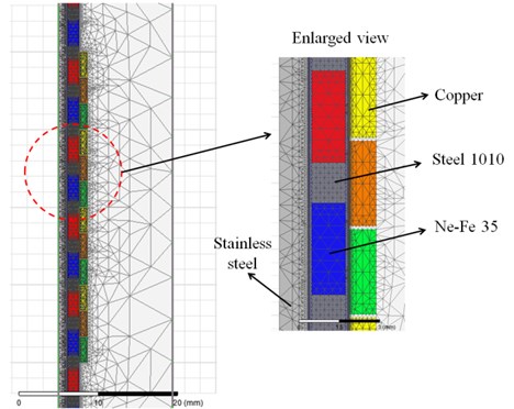
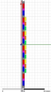
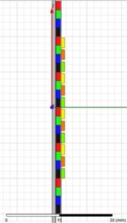
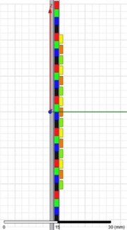
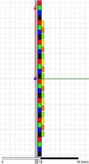
Fig. 8 shows (a) a conventional model uses two-pole 6 permanent magnets, and (b), (c), (d) models of a Halbach array each uses four-pole 6, 7 and 8 permanent magnets. That is, each model uses 12, 24, 28, and 32 permanent magnets.
Fig. 8Model of the proposed generator
a)
b)
c)
d)
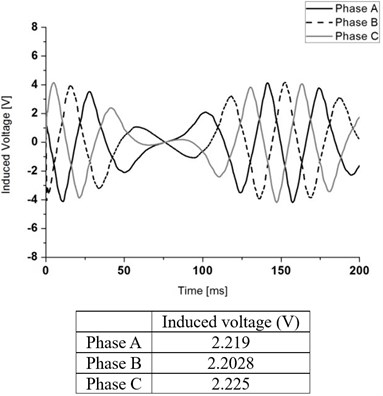
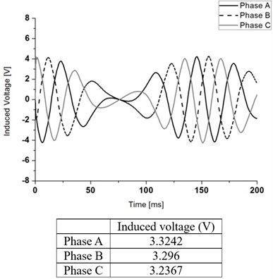
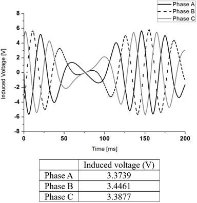
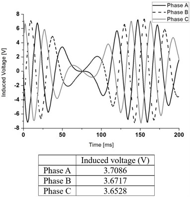
Fig. 9 shows the magnetic flux line plot at initial position. Fig. 10 shows the results of no-load analysis, which shows an electromotive force induced in each model. Phase A, B, and C are shown for each coil.
The root mean square (RMS) value of the induced voltage is an average of value that divided by the square root. The RMS average value of the induced voltage of the conventional model is 2.21 V. The RMS average value of the induced voltage for the model with 6, 7, and 8 permanent magnets of 4 poles is 3.29, 3.37, and 3.7 V, respectively. We confirmed that the Halbach array generator exhibited better performance than the existing generator. When using eight permanent magnets, RMS average value of the induced voltage has an approximately 20 % larger than that of the conventional model.
Fig. 9Magnetic flux line plot at initial position
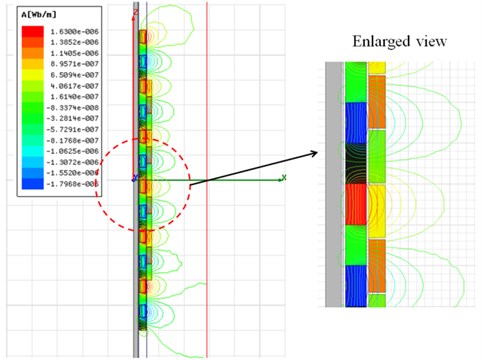
Fig. 10Induced voltage in each coil winding at no load
a)
b)
c)
d)
4. Conclusion
We propose a smartphone embedded linear generator that uses a Halbach array. We analyzed and compared the characteristics of the magnetic field with a conventional smartphone generator by considering the linear generator as the base excitation. In order to produce more power than the conventional generator of a smartphone, we conducted a parameter study for the Halbach array generator in order to select appropriate permanent magnets. To obtain the optimum number of permanent magnets, we conducted an FEA performance analysis. We confirmed FEA by using 4-pole permanent magnets (a total of 32 permanent magnets), RMS value of the induced voltage has approximately 20.24 % larger than the conventional model. Our simulation results show that the proposed design is suitable for practical use.
References
-
Park Semyung, Kim Byunghyun, Kim Sunwoo, Lee Kibum, Kim Jinho. Electric generator embedded in cellular phone for self-recharge. Journal of Vibroengineering, Vol. 16, 2014, p. 3797-3806.
-
Ishiyama M., Makoto I., Kitaoka T., Matsumoto Y., Yagoto M. Linear Motor. Patent #5,955,798, 1999.
-
Murphy B. C. Design and Construction of a Precision Tubular Linear Motor and Controller. M.S. Thesis, Department of Mechanical Engineering, Texas A&M University, 2003.
-
Jang Seok-Myeong, Choi Jang-Young, Lee Sung-Ho, Cho Han-wook, Jang Won-Bum Analysis and experimental verification of moving-magnet linear actuator with cylindrical Halbach array. IEEE Transactions on Magnetics, Vol. 40, Issue 4, 2004, p. 2068-2070.
-
Li Hongfeng, Xia Changlian Halbach array magnet and its application to PM spherical motor. ICEMS International Conference on Electrical Machines and Systems, 2008, p. 3064-3069.
-
Mallinson J. C. One-sided fluxes – a magnetic curiosity? IEEE Transactions on Magnetics, Vol. 9, Issue 4, 1973, p. 678-682.
-
Halbach K. Design of permanent multipole magnets with oriented rare earth cobalt material. Nuclear Instruments and Methods, Vol. 169, 1980, p. 1-10.
-
Winter Oliver, Kral Christian, Schmidt Erich Augmented temperature degrading effect of rare earth magnets arranged in segmented Halbach arrays. IEEE Transactions on Magnetics, Vol. 48, Issue 11, 2012, p. 3335-3338.
-
Choi Jae-Seok, Yoo Jeonghoon Design of a Halbach magnet array based on optimization techniques. IEEE Transcations on Magnetics, Vol. 44, Issue 10, 2008, p. 2361-2366.
-
Trumper David L., Williams Mark E., Nguyen Tiep H. Magnet arrays for synchronous machines. Industry Applications Society Annual Meeting, Vol. 1, 1993, p. 9-18.
-
Jang Seok-Myeong, Jeong Sang-Sub, Ryum Dong-Wan, Choi Sang-Kyu Design and analysis of high speed slotless PM machine with Halbach array. IEEE Transactions on Magnetics, Vol. 37, Issue 4, 2001, p. 2827-2830.
-
Virtic Peter, Pisek Peter, Marcic Tine, Hadziselimovic Miralem, Stumberger Bojan Analytical analysis of magnet field and back electromotive force calculation of an axial-flux permanent magnet synchronous generator with coreless stator. IEEE Transactions on Magnetics, Vol. 44, Issue 11, 2008, p. 4333-4336.
-
Turri S., Miller D., Ben Ahmed H., Multo B. Design on an electro-mechanical portable system using natural human body movements for electricity generation. European Power Electronic Conference, 2003, p. 1-10.
About this article
This research was supported by Basic Science Research Program through the National Research Foundation of Korea (NRF) funded by the Ministry of Education (2013R1A1A2059513).
