Abstract
With the increasing need for more power production by wind turbines and thus increasing in their sizes, importance of accurate designing of wind turbines has substantially increased. One of the major aspects related to the reliability of operation of wind turbines concerns the safe and adequate performance of the blades. It is important that damage to blades is detected before they fail or cause the turbine to fail. Root joints are located in blade root and join blades to the hub. They are significantly affected by fatigue and extreme loads, so damage detection in root joints is vital. In this article a 100 kW wind turbine model was developed and damages in root joints were modeled by reducing their stiffness and the possibility of damage detection in blade root joint was investigated by tracking the dominant frequencies in nacelle and blades. The model considers structural dynamics of the turbine and includes dynamic coupling between the blades and the tower and consists of 11 degree of freedom (two in each of the blades, two for tower and one for each root joint). Finally, numerical simulations were carried out to evaluate the effectiveness of the method for damage detection. Simulation results showed the dominant frequency tracking method has an appropriate capability of detecting damages in the root joints of the wind turbine.
1. Introduction
During the past decades, wind turbine technology has continuously improved and now it is the main alternative energy resource to fossil fuels and it is expected that 10 % of world electricity could be supplied by wind power by 2020 [1]. In a horizontal axis wind power system, turbine blades are used to convert wind energy to electricity. In general, turbine blades are required to be light and have small mass moment of inertia so that they can start to rotate at low wind speed. On the other hand, a wind power system has to survive severe environment for at least 20 years. During its lifetime, a wind blade may experience strong wind with speed as high as 60 m/s and in such condition, the blade should have enough strength to sustain the extreme wind load. In view of these requirements, the reliability of wind turbine blade has become an important topic of research. Although damage can occur to any component or part of the wind turbine, the most common type is rotor or blade damage and tower damage. Thus, special attention should be given to the structural health of blades because they are the elements of a wind power generation system most likely to be damaged and the cost of the blades can account for 15–20 % of the total turbine [2]. Wind turbine blades are vulnerable to cumulative fatigue damage owing to the periodic nature of the loading. Detecting damage to blades before failure is crucial. All Forces and torques applied on blades are transmitted to hub and main shaft through root joint, so blade root and consequently root joint bear maximum stress in blade. Root joints are usually made from aluminum, steel or cast iron and link blade root to hub bearing. Significant research has been carried out into the area of blade design and failure characteristics [3-5]. In many of investigation on blades damages, the root joint and blade root have been identified as the first point of initiating faults like cracks or delaminations.
Cardenas et al. [6] in their study on coupled aeroelastic damage progression for blades indicated that in their all cases, damage had been initiated in the blade root section. Mari’n et al. [7] in their study of fatigue damage detected in blades of a 300 kW wind turbine reported that Most of damages were located in the joining zone of the blade with the root where fatigue loads are more severe. Jui-Sheng et al. [8] in their analysis of wind turbine blade under critical wind loads recognized the box spar cover between the root section webs as the most likely failure location. Chen and Kam [9] in their analysis of small composite sandwich turbine blade subjected to extreme wind loads concluded that in extreme loading, failure location was at the blade root where the fibers of the composite skin ruptured.
The aim of this paper is analyzing changes in oscillatory responses of wind turbine due to damages occurred in blades root joints. All simulations carried out into the model of a 100 kW wind turbine under construction in the Sun-Air Research Institute of Mashhad (SARI) [10] according to the wind data of Binaloud site [11] and dynamic and aerodynamic characteristics of the turbine. The key properties of the turbine are presented in Table 1.
The stiffness of the root joints was reduced in real-time during these simulations. This is essentially modeling the case where the blade root joints lose stiffness due to delamination of metallic and composite layers. The responses obtained from the model simulations were then analyzed by short term Fourier transform to identify blade damage. Nagarajaiah and Varadarajan [12] have developed algorithms to track the dominant frequencies of a system using STFTs. The STFT algorithm splits up the signal into shorter time segments and an FFT is performed on each segment to identify the dominant frequencies present in the system during the time period considered. Combining the frequency spectra of each of these time segments, results in the time frequency distribution of the system over the entire time history. Reducing the stiffness of the root joint to simulate its damage will alter the frequency of vibration of the blade and nacelle and thus allow the damage to be detected.
Table 1Key properties of the wind turbine
Property | Value | Property | Value |
Rating | 100 kW | Cut in rotor speed | 16.7 rpm |
Rotor diameter | 26.2 m | Rated rotor speed | 60 rpm |
Cut-in wind speed | 4 m/s | Nacelle mass () | 5100 |
Rated wind speed | 10 m/s | Rotor mass | 1790 |
Cut-out wind speed | 25 m/s |
2. Dynamic modeling
In dynamic modeling of wind turbine, flexibility of different parts and interaction between blades and tower are important. Ahlstrom [13] carried out research into the effects of increased flexibility in turbine blades and found that it can lead to a significant drop in the power output of the turbine. However, it is only over the last few years that research has started to focus on the dynamic behavior of the turbine blades and the interaction that occurs between the blades and the tower. Two main types of vibration occur in wind turbine blades, flap-wise and edgewise. Edgewise vibrations are vibrations occurring in the plane of the rotor axis. Flap-wise vibrations are vibrations occurring out of the plane of rotation of the blades. Flap-wise vibrations are considered in this paper. Ronold and Larsen [14] studied the failure of a wind turbine blade in flap-wise bending during normal operating conditions of the turbine, while Murtagh and Basu [15] studied the flap-wise motion of wind turbine blades and included their dynamic interaction with the tower. They found that the inclusion of the blade-tower interaction could lead to significant increases in the maximum blade tip displacement [16].
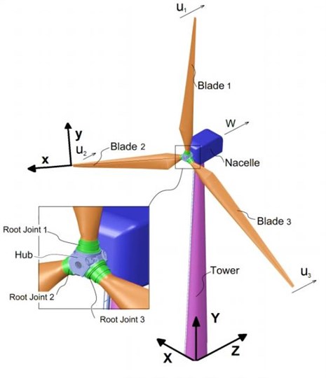
There are quite a number of design codes and simulation software packages available which model the structural behaviour of a wind turbine system. Lee et al. [17] gives an outline of these and the various methods used to solve wind turbine dynamics. The most common approach used by researchers in this area, however, is to formulate the equations of motion by the Lagrangian approach. This allows the derivation of coupling of the numerous flexible bodies (blades, tower, rotor shaft, etc.) and rigid bodies (i.e. yaw mechanism and control actuators) in two or even three dimensional space, directly minimizing the total energy functions of the dynamical system [18, 19]. A Lagrangian formulated model considering only flap-wise vibration is developed for the tower and rotating blades in this paper and subjected to a turbulent wind loading acting solely in the out-of-plane direction of the rotor. The proposed flap-wise system is illustrated in Fig. 1. The model includes two coordinate frames of reference, a local co-rotating system for each blade (, , ) and a global system for the combined elements which includes the tower and nacelle (, , ). At the root of each blade exists the origin of the local blade system. Wind loading is considered in the global -direction as significantly less loading occurs in the other directions [20]. Blades are rotating composite beams with non-uniform cross section and varying density through their length. The key properties of the blades are listed in Table 2. Root joints are massless revolute joints in flap-wise direction with torsional stiffness of which connect blades to the hub. Hub is considered rigid and is fixed to the rotor shaft. Nacelle contains all parts for converting mechanical energy to electrical energy and is considered as a solid mass located on the top of the tower. Tower is a cantilever beam with non-uniform cross section. Details of the key tower properties are outlined in Table 3.
Table 2Key properties of the blades
Property | Value |
Material | Fiber-glass |
Length () | 12.75 m |
Mass | 430 kg |
Center of mass from root | 3.75 m |
Modulus of elasticity () | 18 Gpa |
Root joint stiffness () | 250 kN.m/rad |
Cross section area | Eq. 12 |
Table 3Key properties of the tower
Property | Value |
Material | Steel |
Height () | 30 m |
Mass | 18000 kg |
Center of mass from root | 11.62 m |
Modulus of elasticity () | 200 Gpa |
Top diameter () | 1 m |
Bottom diameter () | 2.5 m |
Cross section area | Eq. (13) |
2.1. Kinetic and potential energy
The kinetic and potential energies of the model were first derived (Eqs. (1), (2)). Total kinetic energy includes kinetic energy of three blades, nacelle and tower. Total potential energy includes potential energy due to deformation of three blades and tower in addition to deformation of root joints:
where is the mass of blade, is the length of the blade, is the mass of nacelle, is the Young’s Modulus for the blade, is the second moment of area of blade, is the stiffness of the root joint, is the generalized displacement of root joint, is the displacement of the blade , is the velocity of the nacelle, is the mass of tower, is the displacement of tower, is the Young’s modulus for the tower, is the second moment of area of the tower, is the tower height. Also is centrifugal force on blades (Eq. (3)) and is absolute velocity of blade including the nacelle motion that causes blade tip displacement, this is a function of both the position along the blade , and time (Eq. (4)):
where is the rotary speed of the rotor.
Fig. 1Wind turbine model
2.2. Assumed mode method
The motion of every substructure may be approximated by a weighted superposition of admissible functions [21]. In the assumed modes method, the solution of the vibration problem of the continuous system is assumed in the form of a series composed of a linear combination of admissible functions , witch are functions of the special coordinates, multiplied by time-dependent generalized coordinates (t). So:
where are admissible functions of tower and blade respectively, and are generalized coordinates of tower and blade respectively. The expressions of kinetic energy (Eq. (1)), potential energy (Eq. (2)) and generalized conservative forces are expressed in terms of the assumed modes solution (Eqs. (8)-(10)) and the Lagrange’s equation (Eq. (7)) are used to derive the equation of motion of the equivalent discrete system of the continuous system:
where is the kinetic energy of the system, is the potential energy of the system, is the displacement of the generalized degree of freedom (DOF) and is the generalized loading for degree of freedom . Also:
In witch is the generalized loading for blades, is the generalized loading for tower, is the generalized loading for root joint. is the aerodynamic force on tower and is the aerodynamic force on blade .
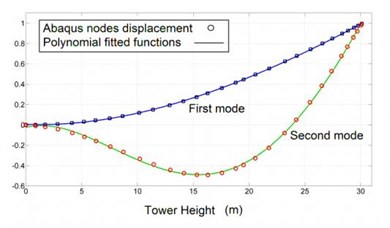
The blades and tower were assumed to be vibrating in their two first modes. Mode shapes were estimated by extracting discrete points on mode shapes from frequency analysis in Abaqus and fitting polynomial functions on Abaqus data. Fig. 2, 3 show two first mode shapes of tower and blades and the path set on their nodes used for extracting mode shapes. Blade mode shapes are affected by centrifugal forces due to rotation of the rotor. Thus before extracting blade mode shapes a rotational body force proportional to the rotor speed was applied on the blade and then frequency analysis carried out. Figs. 4, 5 show fitted polynomial functions on Abaqus discrete points. Eq. (11) presents mode shape functions of the tower and blades. Eq. (12) and Eq. (13) are corresponding to the blade and the tower cross section areas and second moment of areas respectively. Constant values of following equations are listed in Appendix:
The damage detection procedure in this paper only needs dominant frequency of the nacelle vibrations which are caused by the first or second natural frequencies of the tower or the blades, thus tower and each blade are modeled as one element beam which is accurate enough for dynamic modeling of the wind turbine in low frequency vibrations [22].
The model consists of 11 DOF (two in each of the blades, two for tower and one for each root joints) and by using assumed mode method can be expressed in the standard form as in following equation:
where and are the mass and stiffness matrices of the system respectively. and are the acceleration and displacement vectors and is the loading vector.
Fig. 2Two first mode shapes of blades: a) first mode, b) second mode
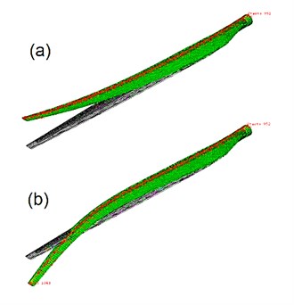
Fig. 3Two first mode shapes of tower: a) first mode, b) second mode
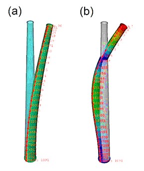
Fig. 4Blade mode shape functions
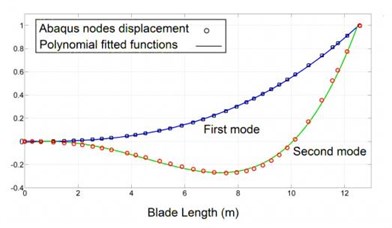
Fig. 5Tower mode shape functions
3. Wind loading
As the wind passes through a wind turbine it generates both a lift and drag force. The lift force is utilized as the main driving force of the blades and acts in the plane of rotation of the blades whereas the drag force acts in the plane parallel to the primary wind flow and therefore in the flap-wise direction of the blades. For the purposes of the model presented here, only the drag force is considered.
There are different ways for modeling aerodynamic loads on blades and tower. In this article according to the characteristics of the turbine and the installation site and according to Risø’s Guidelines for Design of Wind turbines [23] the following equation is proposed to apply the aerodynamic forces on the blades:
where is the cross section area of blade, is the air density, is the wind speed at nacelle height, is the nacelle height, is the blade drag coefficient, is wind shear ratio, is the rotational speed of rotor.
Also loading on the tower was assumed to be a function of tower height as following equation [23]:
where is the tower bottom diameter, is the tower top diameter and is the tower drag coefficient.
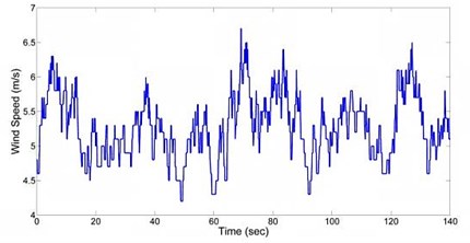
Table 4 outlines numerical values for some parameters of Eq. (15), (16). Other parameters were presented in Tables 2, 3. Fig. 6 shows wind speed at nacelle height for 140 seconds taken from Binaloud site:
Table 4Parameters of the 100 kW wind turbine and wind data of Binaloud site
1.05 kg/m3 | 5.5 m2 | 1.2 | 30 m | 0.2034 | Fig. 6 | 0.6 | 60 rpm |
Fig. 6Wind speed at nacelle height of the 100 kW wind turbine (courtesy with Binaloud site)
4. Results
To obtain the simulation results, equations modeled in Matlab2010/Simulink and solved with the Runge-Kutta method. Fig. 7 shows the response of Blade 1 to turbulent load and Fig. 8 shows the frequency content. Fig. 9 and Fig. 10 show the response of the nacelle to turbulent load and the nacelle response frequency content respectively.
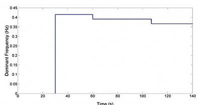
The model was then changed. A loss in stiffness in one root joint was simulated. This is modeling the case where the root joint loses stiffness due to delamination of blade root composite layers and root joint metallic structure. A simulation was set up for 140 seconds. Two losses in root joint stiffness of 1 % and 2 % were applied after 40 and 86 seconds of the simulation respectively. Fig. 11 shows the time history response for Blade 1. Fig. 12 shows the dominant frequency of the blade with respect to time. The STFT was applied at 30 seconds. It is clear that before the root joint stiffness was reduced the dominant frequency in the blade was about 2.5 Hz. However, after the blade’s stiffness was reduced twice the dominant frequency of the blade also reduced for 8 % and 14 %. Fig. 13 plots the nacelle displacement time history. Fig. 14 shows the dominant frequency of the system with respect to time. After that root joint stiffness was reduced two times, the dominant frequency in the nacelle reduced for 6 % and 12 %. Thus reduction of 6 % or 12 % in nacelle dominant frequency or 8 % or 14 % in blade dominant frequency led to a reduction about 10 % or 20 % in blade root stiffness respectively. So dominant frequency tracking was successful in detecting losses in root joints stiffness and hence damage for the turbine. As a result by tracking dominant frequencies of the blades and the nacelle in certain duration in turbine life time it is possible to discover root joints damages by paying attentions to reduction in dominant frequency of the nacelle or the blades.
Fig. 7Blade 1 flap-wise time history response
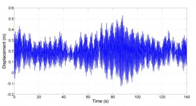
Fig. 8Blade 1 flap-wise frequency spectrum
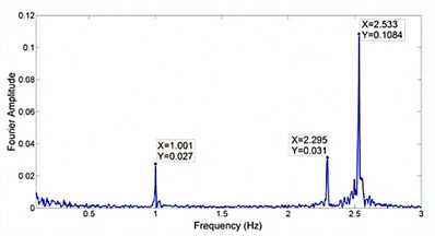
Fig. 9Nacelle time history response
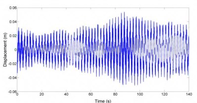
Fig. 10Nacelle frequency spectrum
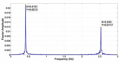
Fig. 11Blade 1 displacement, two losses in stiffness
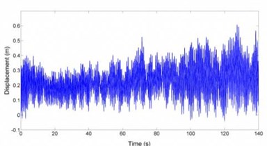
Fig. 12Blade 1 dominant frequency tracking
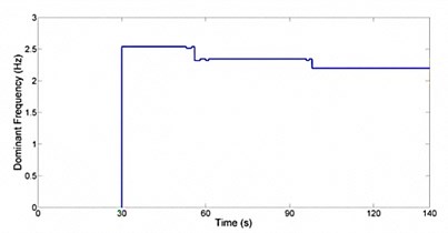
Fig. 13Nacelle displacement, two losses in stiffness
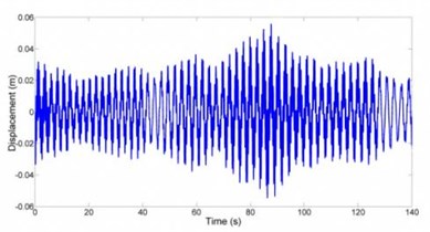
Fig. 14Nacelle dominant frequency tracking
5. Conclusion
In this article an 11 DOF model for a 100 kW wind turbine under construction in Sun-Air Research Institute (SARI) was proposed. Using assumed modes method and Lagrange equation dynamic equations of the turbine were derived. All mode shapes also derived by frequency analysis on CAD model of tower and blades of the turbine in Abaqus. In addition aerodynamic loading on blades and tower according to the characteristics of the turbine and the installation site was considered. By reducing the stiffness value of the root joints, damage was simulated. This in turn had an effect on the natural frequencies of the blades and nacelle. By tracking the dominant frequencies of blades and nacelle over time, simulated damage for the turbine was successfully detected.
References
-
Joselin Herbert G. M., Iniyan S., Sreevalsan E., Rajapandian S. A review of wind energy technologies. Renew. Sustain. Energy Rev., Vol. 11(16), 2007, p. 1117-1145.
-
Ciang C. C., Lee J.-R., Bang H.-J. Structural health monitoring for a wind turbine system: a review of damage detection methods. Meas. Sci. Technol., Vol. 19, 2008.
-
Park J.-H., Park H.-Y., Jeong S.-Y., Lee S.-I. I., Shin Y.-H., Park J. P. Linear vibration analysis of rotating wind-turbine blade. Current Applied Physics, Vol. 10, Issue 2, 2010, p. 332-334.
-
Sutherland H. J., Mandell J. F. Application of the US high cycle fatigue data base to wind turbine blade lifetime predictions. Proceeding of Energy Week, ASME, 1996.
-
Noda M., Flay R. G. J. A simulation model for wind turbine blade fatigue loads. J. Wind Eng. Ind. Aerodyn., Vol. 83, 1999, p. 527-40.
-
Diego Cárdenas, Hugo Elizalde, Piergiovanni Marzocca, Sergio Gallegos, Oliver Probst. A coupled aeroelastic damage progression model for wind turbine blades. Composite Structures, Vol. 94, 2012, p. 3072-3081.
-
J. C. Marin, A. Barroso, F. Paris, J. Canas Study of fatigue damage in wind turbine blades. Engineering Failure Analysis, Vol. 16, 2009, p. 656-668.
-
Jui-Sheng Chou, Chien-Kuo Chiu, I-Kui Huang, Kai-Ning Chi. Failure analysis of wind turbine blade under critical wind loads. Engineering Failure Analysis, Vol. 27, 2013, p. 99-118.
-
C. P. Chen, T. Y. Kam Failure analysis of small composite sandwich turbine blade subjected to extreme wind load. Procedia Engineering, Vol. 14, 2011, p. 1973-1981.
-
Sun-Air Research Institute. Ferdowsi University of Mashhad, Iran.
-
http://www.suna.org.ir/projectdetail-fa-67.html.
-
Nagarajaiah S., Varadarajan N. Short time Fourier transform algorithm for wind response control of buildings with variable stiffness TMD. Engineering Structures, Vol. 27, 2005, p. 431-441.
-
Ahlstrom A. Influence of wind turbine flexibility on loads and power production. Wind Energy, Vol. 9, 2005, p. 237-249.
-
Ronold K. O., Larsen G. C. Reliability-based design of wind-turbine rotor blades against failure in ultimate loading. Engineering Structures, Vol. 22, 2000, p. 565-574.
-
Murtagh P. J., Basu B., Broderick B. M. Along-wind response of a wind turbine tower with blade coupling subjected to rotationally sampled wind loading. Engineering Structures, Vol. 27, 2005, p. 431-441.
-
Fitzgerald B., Arrigan J., Basu B. Damage detection in wind turbine blades using time-frequency analysis of vibration signals. The 2010 International Joint Conference on Neural Networks (IJCNN), 2010, p. 1-5.
-
Lee D., Hodges D. H., Patil M. J. Multi-flexible-body dynamic analysis of horizontal axis wind turbines. Wind Energy, Vol. 5(4), 2002, p. 281-300.
-
Garrad A. Dynamics of wind turbines: physical science, measurement and instrumentation, management and education – reviews. IEEE Proc. A, Vol. 130(9), 1983, p. 523-30.
-
Hansen M. H. Improved modal dynamics of wind turbines to avoid stall induced vibrations. Wind Energy, Vol. 6(2), 2003, p. 179-95.
-
Wind Turbines – Part 1: Design Requirements. British Standards Institution, 2005.
-
Meirovitch L. Analytical Methods in Vibrations. London, Macmillan, 1967.
-
Staino A., Basu B., Nielsen S. R. K. Actuator control of edgewise vibrations in wind turbine blades. Journal of Sound and Vibration, Vol. 331, 2012, p. 1233-1256.
-
DNV/Risø’s Guidelines for Design of Wind Turbines, ISBN 87-550-2870-5.
About this article
