Abstract
The rapping acceleration of collecting plates in electrostatic precipitator system determines the dust- rapping performance of electromagnetic vibration exciter. To maximize the acceleration, the resonance phenomena needs to be driven by matching the mechanical natural frequency of the electrostatic precipitator system and the input frequency of electric current which energizes the electromagnetic vibrator. In this paper, the dust collecting plates and the electromagnetic vibration exciter in electrostatic precipitator system are vibration-modeled mathematically to characterize the resonance frequency. The effective mass and stiffness for each mode of the collecting plates are calculated using finite elements analysis and the natural frequency are computed by the method of least error square. In addition, the effective mass and stiffness of the exciter are computed. Then, the whole electrostatic precipitator system is analyzed. A frequency response analysis based on a sine sweep signal experiment is performed on a prototype for verification of calculated theoretical resonance frequency.
1. Introduction
There are several methods for dust rapping on the electrostatic precipitators; these include motor-driven swing hammers and wet cleaning types. However, there are various problems with these methods. The motor-driven swing hammer has good rapping performance, but it occupies considerable space and has breakdown risk of collecting plates. The wet cleaning method is clean all the time due to continuous water screening during operation, but it may rust, freeze, or burst at low temperatures [1]. Consequently, an electrostatic precipitator that uses an electromagnetic vibration exciter was proposed to improve the performance of typical rapping systems [2]. Figure 1 shows the schematic diagram which consists of the dust collecting plate, electromagnetic vibration exciter and a stinger.
Fig. 1Schematic diagram of the ESP system
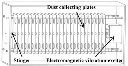
Dust in the air is collected on steel plates by corona discharger [3]. Usually, these dusts are usually fly ash and Particulate Matter-10 (PM-10) and it settles on the collecting plates in over 1 mm of thickness [4]. To vibrate these collecting plates for dust rapping, electromagnetic vibration exciter are used. Figure 2 and Table 1 show schematic diagram of electromagnetic vibration exciter, and its specification. A quadratic electromagnetic vibration exciter which is shown on Figure 2 has better magnetic flux on air gap, so it has better efficiency. Operating principle of this exciter is following steps. When the sinusoidal electric current energizes coil, electromagnetic vibration exciter starts to vibrate by Lorentz force. Equation (1) describes the Lorentz force. The number of coil turns is , the intensity of the magnetic flux in the air gap is , the input current is , and the effective coil length is :
The electromagnetic vibration exciter is connected to all collecting plates through a stinger. Collected dust on the collecting plates is rapped out by vibration force which came from reciprocating motion of the electromagnetic vibration exciter. Generally, it needs the rapping acceleration between 20 g and 50 g for effective dust rapping [1, 2]. To maximize the acceleration of collecting plate, the resonance phenomena needs to be driven by matching the mechanical natural frequency of the collecting plates and the input frequency of electric current which energizes the electromagnetic vibration exciter. Therefore, it is important to find the mechanical natural frequency of electrostatic precipitator system which is compsoed of the dust collecting plates and electromagnetic vibration exciter [5].
In this research, a mathematical modeling process for the electrostatic precipitator system is introduced using finite element analysis and the method of least squares. For verification of mathematical model, a frequency response analysis based on a sine sweep signal experiment is performed on the prototype.
Fig. 2Schematic diagram of the electromagnetic vibration exciter
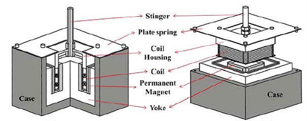
Table 1Specification of the electromagnetic vibration exciter
Specification of exciter | ||
Number of coil turns | 400 turns | |
Input current | 1 A ~ 10 A | |
Outer magnet | Thickness | 5 mm |
Size | 100 mm×50 mm | |
Inner magnet | Thickness | 10 mm |
Size | 50 mm×50 mm | |
Exciter | Size | 150 mm×150 mm×70 mm |
2. Pre-Analysis for mathematical modeling
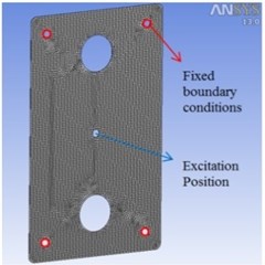
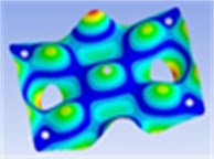
Fig. 3(a) shows the schematic diagram of a collecting plate. To derive effective mass and stiffness of this collecting plate, harmonic and modal analyses are performed by ANSYS Workbench [6]. The boundary conditions in finite element model are defined on four holes around edge as shown Fig. 3(b).
Fig. 3a) Design of a collecting plate, b) finite element model of a collecting plate
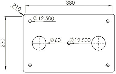
a)
b)
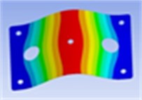
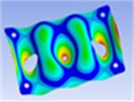
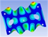
Mesh size was 10 mm. 995 ea of SOLID186 element type which has 20 nodes and 8 ea of SURF156 element type which has 3 nodes were set as mesh element to finite element model of the collecting plate, about 141 seconds was taken to perform a trial of finite element analysis. We conducted 5 times of analysis and used average values of them to reduce error of ANSYS itself. Through harmonic response analysis, we analyzed the frequency response for steady state excitation at the central position of the collecting plates. Then, using modal analysis, we obtained nine vibration mode shapes and frequencies of the collecting plates as shown in Table 2.
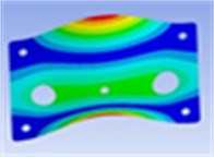
Table 2Modal shapes of the collecting plate
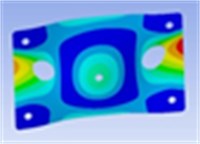
1st mode | 2nd mode | 3rd mode |
Frequency: 20.3 Hz | Frequency: 56.4 Hz | Frequency: 85.6 Hz |
 |  |  |
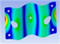
4th mode | 5th mode | 6th mode |
Frequency: 113.9 Hz | Frequency: 166.9 Hz | Frequency: 244.1 Hz |
 | 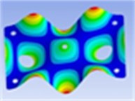 | 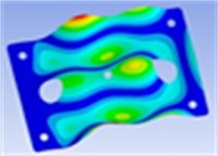 |
7th mode | 8th mode | 9th mode |
Frequency: 253.4 Hz | Frequency: 334.8 Hz | Frequency: 349.3 Hz |
 |  |  |
3. Theoretical analysis for effective mass and stiffness
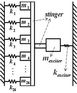
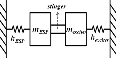
The system is approximated to vibration system as Figure 4 for mathematical approximation, and whole collecting plates are assumed that parallel connected. Effective mass of each collecting plate is abbreviated as , effective stiffness of collecting plates as , effective mass of the exciter as , and effective stiffness of the exciter as . In this chapter, effective mass and stiffness of the electromagnetic vibration exciter were not considered to derive precise value of effective mass and stiffness of the collecting plates only.
Fig. 4Vibration modeling of the ESP system
At this stage in the analysis, we used the method of least squares on a 1-dof model. The first parameter to determine is target error about optimal line which will be properly decreased by method of the least error square [7]. Eq. (2) is a motion equation of the undamped system that is excited by harmonic force, where is the applied harmonic force on the collecting plate:
Table 3 gives main three physical factors which are derived through the least error square method.
Table 3Formulas from the least error square method
Formula | Physical factor |
Amplitude of the system | |
Estimated error | |
Effective mass and stiffness matrix |
Table 4 shows the values of the effective mass and stiffness of the collecting plate for each mode by solving effective mass and stiffness matrix from the least error square method.
Table 4Effective mass and stiffness for each mode
Mode | Effective mass [kg] | Effective stiffness [N/m] |
1 | 0.1272 | 2.0670×10³ |
2 | 0.1681 | 2.1085×10⁴ |
3 | 0.1510 | 4.3686×10⁴ |
4 | 0.1392 | 7.1283×10⁴ |
5 | 0.1400 | 1.5403×10⁵ |
6 | 0.1778 | 4.1829×10⁵ |
7 | 0.0453 | 1.1486×10⁵ |
8 | 0.1713 | 7.5777×10⁵ |
9 | 0.0931 | 4.4820×10⁵ |
4. Vibrational experiments
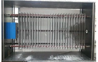
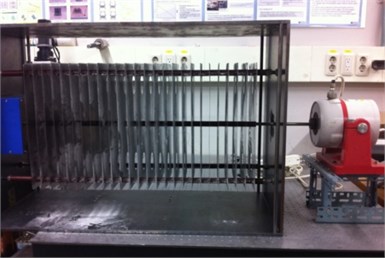
In order to compare resonance frequencies from our theoretical (mathematical) analysis of the collecting plates with experimental results, the prototype was made, and frequency response experiment was performed using a 10 to 210 Hz sinusoidal sweep signal input to the 26 EA of collecting plates. Figure 5 shows the electrostatic precipitator prototype. The prototype precipitator is composed of 26 of collecting plates, cases, 4 fixation bars, insulators, and a stinger for connecting each collecting plate. 26 of collecting plates are connected to reference shaker.
Fig. 5Prototype of the ESP with the reference shaker
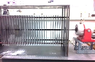
Fig. 6Schematic diagram of the experimental setup
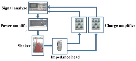
Figure 6 shows a schematic diagram of a vibration measuring experiment setup for the electrostatic precipitator. The system was excited by the shaker to find the resonance frequency with using a signal analyzer. The generated force and acceleration were measured using an impedance head which is located between the electrostatic precipitator and a shaker. The voltage level of each signal was very small, so the signals were amplified by amplifiers. The amplified signals were sent to a signal analyzer, and the frequency responses of the dust collecting plates were obtained [2].
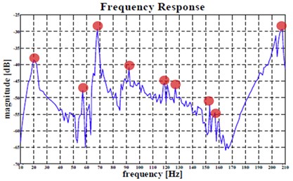
When the input frequency increased, higher plate modes were generated accordingly as Figure 7 shows. Table 5 shows the theoretical natural frequency and the experimental natural frequency respectively.
Fig. 7Nine assumed frequency response peak points of 26 collecting plate, excited at the center
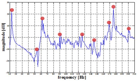
Table 5Theoretical and experimental natural frequency of 26 collecting plates
Mode | Theoretical natural frequency [Hz] | Mode | Experimental natural frequency [Hz] |
1 | 20.29 | 1 | 17.64 |
2 | 56.37 | 2 | 50.53 |
3 | 85.61 | 3 | 76.06 |
4 | 113.89 | 4 | 100.01 |
5 | 166.94 | 5 | 146.72 |
6 | 244.11 | 6 | 220.28 |
7 | 253.43 | 7 | 183.70 |
8 | 334.74 | 8 | 300.69 |
9 | 349.21 | 9 | 291.56 |
5. Modeling of electrostatic precipitator with electromagnetic exciter
In this chapter, the resonance frequency of the whole electrostatic precipitator system includes the electromagnetic vibration exciter was calculated. In previsous chapters, the natural frequency of collecting plates only was calculated and verified by mathematical modeling and frequency response experiment. However, the electromagnetic vibration exciter has addictive mass and stiffness effects on the resonance frequency of the electrostatic precipitator system unlike the reference shaker that transfers the excitation force only. The resonance frequency which considers the additive effective mass and stiffness of electromagnetic vibration exciter is newly computed and compared with the natural frequency of collecting plates only. 26 EA of collecting plates with the electromagnetic vibration exciter can be simplified and modified free body diagram of 1 DOF vibration. Figure 8(a), (b) show the prototype of electrostatic precipitator with the electromagnetic vibration exciter, and modified its free body diagram. In the free body diagram, the total effective mass and the total effective stiffness of the electrostatic precipitator (which are 26 of collecting plates) are and while the effective mass and stiffness of the electromagnetic vibration exciter are and . And mass of stinger is .
Fig. 8a) The prototype of the electrostatic precipitator with the electromagnetic exciter, b) modified free body diagram of the electrostatic precipitator with the electromagnetic exciter
a)
b)
Before the whole system was analyzed, effective mass and stiffness of the collecting plates were used same value from FEM model as chapter 2 and mathematical method for obtaining the effective mass and stiffness of the electromagnetic vibration exciter was same with one for the collecting plates shown in previous chapters. Table 6 shows effective mass and stiffness of the electromagnetic vibration exciter. Effective mass and stiffness were multiplied by 26 to apply number of collecting plates and these values added to electromagnetic vibration exciter’s effective mass and stiffness Theoretical of the whole system was calculated by an equation (3) with these values. Table 7 shows the natural frequencies of the precipitator system (26 of collecting plates with electromagnetic vibration exciter):
Fig. 9The electromagnetic vibration exciter for the experiment
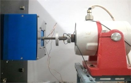
Table 6Effective mass and stiffness of the electromagnetic vibration exciter
Mode | Effective mass [kg] | Effective stiffness [N/m] |
1 | 0.639 | 1.4626×10⁴ |
2 | 0.523 | 1.2942×10⁶ |
3 | 0.021 | 9.9063×10⁴ |
As mentioned earlier, among vibration modes of the exciter, only 1st mode values were considered as effective results because the 2nd and 3rd mode were generated by non-axial direction motion, not the axial direction of the stinger which does not generate our intended dust rapping [2]. For verification by the experiment, the electrostatic precipitator system with the electromagnetic exciter was connected to the reference shaker as Fig. 10(a). Frequency response experiment was performed as previous chapter. Fig. 10(b) shows its results.
Table 7Natural frequencies of the precipitator system (electrostatic precipitator equipped with the exciter)
Mode of collecting plates | Natural frequency [Hz] | ||
Mode of exciter | |||
1st mode | 2nd mode | 3rd mode | |
1 | 19.35 | 83.50 | 29.67 |
2 | 50.06 | 88.49 | 54.80 |
3 | 74.54 | 105.74 | 79.12 |
4 | 97.89 | 123.66 | 102.42 |
5 | 143.29 | 160.13 | 148.19 |
6 | 215.47 | 222.97 | 220.87 |
7 | 174.49 | 198.02 | 185.85 |
8 | 294.13 | 296.67 | 300.87 |
9 | 281.13 | 286.52 | 291.91 |
Fig. 10a) The electrostatic precipitator with the electromagnetic vibration exciter system for experiment, b) nine assumed frequency response peak points of the system, excited at the center
a)
b)
6. Conclusions
In this thesis, mathematical modeling of the electrostatic precipitator system using resonance phenomena is proposed. Natural frequency of the electrostatic precipitator was calculated by the method of least error square, harmonic response and modal analysis. Furthermore, this mathematical modeling was verified by comparison with experimental results which were from frequency response experiments. The mathematical modeling showed about 90 % of preciseness in natural frequency through this comparison at principal modes from 1st to 3rd which is utilized for vibration dust rapping. About 10 % of error was caused by the experimental setup such as a gap between the insulators and fixation bars for the insulation and support of each plate.
Although there were slight errors on natural frequency, the mathematical model will be helpful for finding or predicting approximate natural frequency of the electrostatic precipitator systems for effective rapping.
References
-
Salbert Oglesby, Grady B. Nicholas Electrostatic Precipitation. Dekker Marcel Inc., New York, 1978.
-
J. H. Kim, J. H. Kim, S. H. Jeong, B. W. Han Design and experiment of an electromagnetic vibration exciter for the rapping of an electrostatic precipitator. Journal of Magnetics, Vol. 17, No. 1, 2012, p. 61-67.
-
J. S. Chang Corona Discharge Processes. IEEE Journals, Vol. 19, Issue 6, 1991, p. 1152-1166.
-
Paul E. Morrow, Thomas T. Mercer A point-to-plane electrostatic precipitator for particle size sampling. American Industrial Hygiene Association Journal, Vol. 25, Issue 1, 1964, p. 8-14.
-
Jaehee Kim, Junhyung Kim, Jinho Kim Robust design of air compress-driving quadratic linear actuator in fuel cell BOP system using Taguchi method. Journal of Magnetics, Vol. 17, No. 4, 2012, p. 275-279.
-
D. J. Mead, Y. Yaman The harmonic response of rectangular sandwich plates with multiple stiffening: a flexible wave analysis. Journal of Sound and Vibration, Vol. 145, Issue 3, 1991, p. 409-428.
-
Jack R. McDonald,Wallace B. Smith, Herbert W. Spencer III, Leslie E. Sparks A mathematical model for calculating electrical conditions in wire‐duct electrostatic precipitation devices. Journal of Applied Physics, Vol. 48, Issue 6, 1977, p. 2231-2243.
About this article
This research was supported by the Urban Railroad Technology Development Program (Grant 09 Urban Railroad A-01), funded by Ministry of Land, Transport and Maritime Affairs of the Korean Government. The authors gratefully acknowledge this support.
