Abstract
Non-destructive damage identification is one of the most important problems in maintenance and reliability of composite structures. The methods applied for damage identification should be sensitive for external and internal damages and provide their precise localization. One of the promising methods for the damage identification is the wavelet transform applied to modal shapes of investigated objects. If the investigated object has circular geometry it is suitable to adapt the algorithm of damage identification to polar coordinate system. The paper presented an application of polar wavelet transform in order to detect and identify various types of damages occurred in composite structures with circular geometry. Several (external and internal) types of damages were considered in the presented study. Basing on comparative study the most adequate polar wavelets for damage identification problems were selected.
1. Introduction
An improvement of technology of polymeric composite materials in last decades decided on the still growing applicability of composites as a constructional material in various branches, including automotive and aircraft industries, ship-building, building of wind turbines, sport equipment design etc. According to the growing number of machines and devices contained elements made of polymeric composites it was necessary to develop suitable diagnostic methods in order to monitor their condition and detect and identify eventual damages occurred during their operation. These methods should be non-invasive and non-destructive and should allow for the detection and identification of even small damages occurred in the tested structure.
There are a lot of developed methods and techniques used for non-destructive damage detection and identification in composite materials, including thermography, radiography, shearography, ultrasonic and hydro-ultrasonic methods, fiber optic methods, acoustic emission methods etc. In the most cases the application of such method needs special measurement equipment and is limited to the laboratory tests. Another large group of methods used for damage identification in composite structures is the vibration-based methods. Vibration tests and modal analysis could be carried out directly in operation conditions, often without necessity of disassembling of the investigated element from the device.
The analysis of raw measurement data collected from vibration tests do not gives information about technical state of the element besides its frequency response, which, in the case of elements made of polymeric composites, may significantly changes depending on several factors, e.g. temperature, humidity, boundary conditions, workload etc. The analysis based on Fourier transform or determination of statistical features of the measured time series could only detect the damage and only in the case, when the damage is sufficiently large. For the detection of smaller damages and its identification some advanced signal processing methods were used. One of the effective methods is the application of wavelet transform (WT) to the measured signals in order to extract subtle changes in these signals and basing on these change conclude about the damage. The popularity of the application of WT in problems of structural diagnostics could be observed in the last decade. The methods based on WT reveal good precision of damage localization and identification and allow for concluding about presence of the damage without the necessity of comparison of signal for the damaged structure with signals of the healthy one. One-dimensional (1D) structural diagnostic problems with use of WT were presented by the several authors, e.g. [1-3]. However, the practical needs required to extend this method into two-dimensional (2D) domain. Some numerical and experimental studies of damage identification in 2D structures were performed in [4-7], where the authors used Continuous Wavelet Transform (CWT) with different types of wavelets. Results obtained in previous author’s studies show, that CWT is a redundant transform and the application of Discrete Wavelet Transform (DWT) in 1D [8] and 2D [9] damage identification problems allow for fastening of the algorithm without loss (or even improving) of accuracy by using special types of wavelets. There are only several works, which discussed the application of DWT for structural diagnostics problems. The authors of [10] used DWT for the damage identification basing on measurements using piezoelectric transducers. The experimental studies of structural health monitoring of aircraft elements using DWT with various wavelets was presented by Smith et al. [11]. Another approach was presented by the authors of [12]: they used both CWT and DWT for the analysis of acoustic emission signals in order to detect the damages in composite structures.
The problems of damage identification presented in the above-cited papers describe the algorithm for rectangular-shaped structures, i.e. the WT was performed in rectangular coordinate system. However, in many cases of engineering structures and structural elements it is necessary to diagnose circular-shaped structures and therefore it is necessary to formulate the algorithm in polar coordinates. Several formulations of polar WT and wavelets in polar coordinates could be found in available literature, e.g. [13, 14], and application of polar WT in different engineering problems such as gears diagnostics [15], three-dimensional content search and retrieval problem [16], data mining applications [17], computer tomography image filtering [18] etc.
The aim of this paper is the formulation of fundamentals of the polar WT and its application for damage identification problem of composite circular-shaped structures. The new algorithm of damage identification based on DWT was presented and the crucial aspects of its application were discussed. The identification was carried out based on numerical data both for external and internal damages, which show the universality and great sensitivity of the algorithm. The comparative study of different 2D polar wavelets was performed in order to find potentially the best wavelet for structural diagnostics problems.
2. Polar discrete wavelet transform
The DWT algorithm is based on multiresolution signal representation introduced by Mallat. Following this, the basic element of multiresolution representation in square-integrable space is a sequence of closed functional spaces :
with properties:
Considering that the 2D signal is represented by two variables in polar coordinates:
where and are the radial and angular variables, respectively.
The functions , determine the orthonormal base in for various translations and with respect to and :
with taking into account the rectangular-polar conversion expressions:
Similarly, the functions:
following to the dyadic representation [19] and considering (3) and (5), constitute the orthonormal base in , where is the approximation level.
If the applied 1D wavelet has a separability property then it could be extended to the 2D domain using tensor product operation on combinations of scaling and wavelet functions. Let us define such a construction using supplementary space of in the space. In this case consists of three parts with orthonormal bases: for , for and for , which defines the wavelets. Considering this, the scaling function and three wavelets could be described as follows:
where , and denote radial, angular and coupled wavelets, respectively. Basing on these statements the 2D polar scaling and wavelet functions could be constructed if the initial 1D scaling and wavelet functions fulfill several conditions, e.g. separability, orthogonality (semi- or biorthogonality) and compact support. Exemplary 2D polar scaling and wavelet functions were presented in Fig. 1 and Fig. 2.
Fig. 12D polar Daubechies 3: a) scaling function, b) radial wavelet, c) angular wavelet, d) coupled wavelet
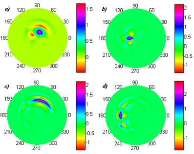
Fig. 22D polar B-spline 3: a) scaling function, b) radial wavelet, c) angular wavelet, d) coupled wavelet
In the cases when the circular-shaped structure was considered for an analysis the classical 2D DWT in rectangular coordinates could be also applied, but during such a transform obtained wavelet coefficients near the border of the investigated structure will be biased by the boundary effect, which make impossible a proper detection and localization of damages in this region. The transformation of obtained coefficients from rectangular to polar coordinates will always generate correlated noise [13], which diminishes the sensitivity of the damage identification method. Thus, the DWT in polar coordinate system seems to be the most suitable for the damage identification problem of circular-shaped structures.
3. Damage identification
3.1. Preparation of numerical data
In order to present the damage identification problem in circular-shaped elements the finite element (FE) models of circular plates clamped on the boundary were prepared. The model definition and numerical calculations were carried out in the MSC Marc/Mentat® FE commercial software. The plates with the radius of 0.25 m and the thickness of 0.0024 m were modelled as 12-layered glass-fiber reinforced polymer laminate with the layers orientation given by the structural formula:. Eachlayerhasaconstantthicknessof 0.0002 m. The material properties were assumed from [20].
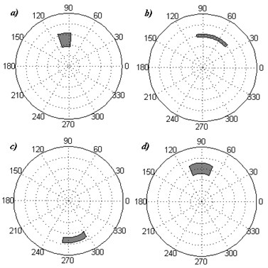
The modelled plates included artificial damages: two cases with damages on the surfaces of the plates and two cases with internal damages in the form of the delamination and the void. Such cases of damages were chosen in order to simulate typical damages of polymeric laminates occurred during its manufacturing and operation. The damages on the surface and the internal void were modelled by excluding elements from the model following the presented schemes (see Fig. 3a, 3b and 3d), while the delamination was modelled by deactivation of contact between two layers as it was shown on Fig. 3c. The depth in the first case of damage (Fig. 3a) was , while in the second case of damage (Fig. 3b) it was .
The numerical analysis was performed in order to determine first four modal shapes of the plates. The nodal displacements in the axial direction were considered for the further analysis. The nodes’ grid has the dimensions of 50 elements in radial direction and 100 elements in axial direction, which resulted in 5001 nodes considered. In further analysis four first modal shapes were considered. Collected nodal displacements were imported to the MATLAB® environment.
3.2. Damage identification algorithm
The proposed algorithm of damage identification is based on DWT and Inverse DWT following to the previous findings presented in [9]. Collected data of displacements of modal shapes were decomposed onto a set of approximation coefficients and three sets of detail coefficients: radial, angular and coupled. Following the idea of DWT the detail coefficients consist information about detected singularities in the analysed signal, thus these coefficients were considered for the damage identification. Regarding to the fact that DWT causes dimensional reduction of an initial signal (from to ), it is necessary to reconstruct obtained coefficients. However, considering that the information about the damage includes in the sets of detail coefficients, the IDWT is applied for each set of detail coefficients separately without taking into consideration the set of approximation coefficients.
As it was reported in [9], the detail coefficients are strongly dependent on the magnitudes of displacements, i.e. for the regions of the tested element, where magnitudes of displacements are relatively high, the magnitudes of detail coefficients in these regions are also high. Thus, in the case of damage presence in the considered regions it will be detectible as well. In order to avoid the influence of magnitude of displacements and increase the sensitivity of a method for small damages it is suitable to add up obtained detail coefficients for various modal shapes. Considering also a fact that the sign of detail coefficients changes alternately along rows and columns of the investigated signal it is profitably to consider absolute values of detail coefficients, which additionally emphasizes the magnitude of coefficients during adding up operation. The resulting formula of the post-processing of data after above-discussed decomposition-reconstruction procedures could be expressed as:
where denotes the set of added up absolute values of coefficients (radial, angular and coupled) for considered modal shapes.
Fig. 3Location of the damages: a), b) on the surfaces, c) delamination between two most upper layers, d) internal void in the 11th layer from the bottom
Such an algorithm was tested on numerical data prepared following above-presented description. In the next section the results of damage identification were showed and discussed.
4. Analysis of results
4.1. Results of damage identification
The identification of artificial damages considered in this study (see Fig. 3) was carried out following to the presented algorithm. For the decomposition-reconstruction procedure the polar 2D Daubechies wavelet of order 3 was chosen. The absolute values of reconstructed detail coefficients for four considered modal shapes were added up using (8). Obtained sets of -coefficients were presented in Fig. 4.
Analyzing presented sets of -coefficients it could be noticed, that the damages were detectable in each case, nevertheless in particular cases the decision about the damage presence and location could be ambiguous. Let us analyze the factors influenced on the effectiveness of the damage identification. In the case of the first surface damage (Fig. 4a) the magnitude of -coefficients achieves the highest values in the region of damage location (cf. Fig. 3(a)) due to the fact that the sampling points in this region were actually on the 11th layer from the bottom. This causes discontinuity in displacements magnitude with the region outside of the damage. Disregarding the presence of the noise caused by decomposition-reconstruction operation the damage could be clearly identified. In the second case (Fig. 4(b)) the damage was located between the sampling points, which cause lower clearness of the observed set, however in the damaged region the magnitude of -coefficients are the highest. In the cases of delamination (Fig. 4(c)) and internal void (Fig. 4(d)) the location and shapes of damages could be clearly identified. It was resulted by the great influence of the artificial damages on the modal shapes, i.e. the damages cause great local singularities following to the stiffness reduction. It could be also confirmed by the comparison of magnitudes of -coefficients presented in Fig. 4.
As it could be noted before the sensitivity of an algorithm is depended on the magnitudes of displacements of the considered modal shapes. The summation approach (8) in fact increases the detectability of the damage, however it may cause blurring of the -coefficients in the damaged region.
Fig. 4Results of damage identification for the investigated cases
4.2. Analysis of a wavelet type used for damage identification
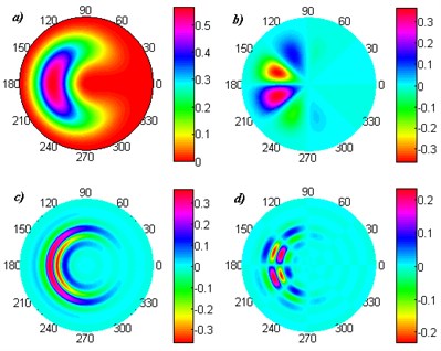
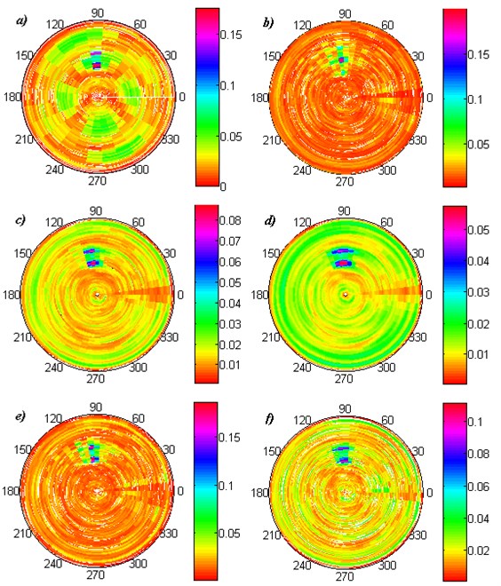
Previous studies of the author [9] and other studies presented in [5-7] show, that the great influence on the accuracy of damage detection and identification have the applied wavelet. Results in [9] presented a comparative study of different wavelets used for the damage identification in square composite plates. Following this it is suitable to perform such a study for the investigated problem, which uses 2D polar wavelets, and discuss the influence of properties of these wavelets on the accuracy of the damage identification. For this study the first case of damage (Fig. 3(a)) was chosen. The analysis was performed using various 2D polar wavelets constructed from 2D wavelets used in [5, 6, 9] and some other wavelet commonly used in the damage identification problems. The influence of order of applied wavelets was also considered. Obtained sets of -coefficients were presented in Fig. 5.
The comparison of damage identification results using different wavelets show, that the best identification of the damage shape was achieved using Daubechies 3 wavelet (Fig. 4(a)), however during increasing the wavelet order to 6 the damage is poorly identifiable (Fig. 5(b)). Other applied wavelets detected only the boundaries of the damage, the most clear results were obtained using 2D polar B-spline 6 wavelet. Similar results for this wavelet in the comparative study were achieved in [9] in rectangular coordinates. The case analyzed using Haar (or Daubechies 1) wavelet consists of a lot of high-magnitude -coefficients, similarly as the case analyzed with Symlet 6. The analysis of order of the applied wavelets show that for higher orders the damage location became unsharp (cf. e.g. Fig. 5(c) and Fig. 5(d)), which was caused by decreasing of maximal amplitude of wavelet and the greater number of vanishing moments, while its order increases. Moreover, comparing the presented results with the results achieved in [9] for square plates it could be noticed that the influence of the accuracy and clearness of identification with a given wavelet has the number of considered measuring points (or the dimension of measuring points’ grid). This phenomenon needs additional analyses, which will planned for further works.
Obtained findings should be applicable for the damage identification basing on experimental data. It is obvious that the experimental data are biased by measurement noise and the sensitivity of the method will decreases. The considered artificial damages presented in this paper are comparable with the damages described in [9]. The method was tested basing on experimental measurements using laser Doppler scanning vibrometer, which characterizes by high value of signal-to-noise ratio. The proposed method applied to experimental data show good detectability in all investigated cases of damages. Therefore, the method could be applied for experimental data processing for the measurements made on precise measurement systems, e.g. laser Doppler vibrometers, fiber Bragg gratings, etc.
Fig. 5Results of damage identification using 2D polar: a) Haar, b) Daubechies 6, c) B-spline 3, d) B-spline 6, e) Symlet 6, f) reversed biorthogonal 5.5 wavelet
5. Conclusions
The damage identification problem in the circular-shaped composite structures using polar discrete wavelet transform was considered in this paper. The identification algorithm is based on detection of singularities in axial displacements of natural vibration modal shapes. Proposed algorithm allow for avoiding several technical problems caused by decomposition-reconstruction procedure during application of DWT and IDWT and improving the detectibility of the damages. The analysis was performed on numerical data with modelled external and internal damages of a composite plate. Obtained results show great performance of the proposed method, which could be applied in practical realizations of structural diagnostics as well. Results of comparative study prove that the crucial influence of the damage detectibility has the appropriately chosen wavelet. The method was tested in experimental conditions for square composite plates (see [9]) and reveals good detectibility of damages. However, the additional experiments for the circular plates will be carried out in further works in order to test polar DWT.
References
-
Douka E., Loutridis S., Trochidis A. Crack identification in beams using wavelet analysis. International Journal of Solids and Structures, Vol. 40, 2003, p. 3557-3569.
-
Kim H., Melhem H. Damage detection of structures by wavelet analysis. Engineering Structures, Vol. 26, 2004, p. 347-362.
-
Li Z., Xia S., Wang J., Su X. Damage detection of cracked beams based on wavelet transform. International Journal of Impact Engineering, Vol. 32, 2006, p. 1190-1200.
-
Chang C. C., Chen L. W. Damage detection of a rectangular plate by spatial wavelet based approach. Applied Acoustics, Vol. 65, 2004, p. 819-832.
-
Loutridis S., Douka E., Hadjileontiadis L. J., Trochidis A. A two-dimensional wavelet transform for detection of cracks in plates. Engineering Structures, Vol. 27, 2005, p. 1327-1338.
-
Rucka M., Wilde K. Application of continuous wavelet transform in vibration based damage detection method for beams and plates. Journal of Sound and Vibration, Vol. 297, 2006, p. 536-550.
-
Fan W., Qiao P. A 2-D continuous wavelet transform of mode shape data for damage detection of plate structures. International Journal of Solids and Structures, Vol. 46, 2009, p. 4379-4395.
-
Katunin A. Identification of multiple cracks in composite beams using discrete wavelet transform. Scientific Problems of Machines Operation and Maintenance, Vol. 45, 2010, p. 41-52.
-
Katunin A. Damage identification in composite plates using two-dimensional B-spline wavelets. Mechanical Systems and Signal Processing, Vol. 25, 2011, p. 3153-3167.
-
Su Z., Ye L., Bu X. A damage identification technique for CF/EP composite laminates using distributed piezoelectric transducers. Composite Structures, Vol. 57, 2002, p. 465-471.
-
Smith C., Akujuobi C. M., Hamory P., Kloesel K. An approach to vibration analysis using wavelets in an application of aircraft health monitoring. Mechanical Systems and Signal Processing, Vol. 21, 2007, p. 1255-1272.
-
Marec A., Thomas J.-H., El Guerjouma R. Damage characterization of polymer-based composite materials: Multivariable analysis and wavelet transform for clustering acoustic emission data. Mechanical Systems and Signal Processing, Vol. 22, 2008, p. 1441-1464.
-
Andric O., Johnston C., Erdol N. Wavelets in polar coordinates. IEEE International Conference on Acoustics, Speech, and Signal Processing, Vol. 3, 1996, p. 1507-1510.
-
Liu Y., Wong M. W. Polar wavelet transforms and localization operators. Integral Equations and Operation Theory, Vol. 58, 2007, p. 99-110.
-
Meltzer G., Dien N. P. Fault diagnosis in gears operating under non-stationary rotational speed using polar wavelet amplitude maps. Mechanical Systems and Signal Processing, Vol. 18, 2004, p. 985-992.
-
Daras P., Zarpalas D., Tzovaras D., Srtintzis M. G. 3D content-based search and retrieval using the 2D polar wavelet transform. IEEE International Conference on Image Processing, Vol. 2, 2005, p. 1146-1149.
-
Kang S., Lee S., Lee S. A novel wavelet transform based on polar coordinates for datamining applications. Lecture Notes in Computer Science, Vol. 3614, 2005, p. 1150-1153.
-
Prasad R. J. C., Sreenivasu T., Rao N. V. G. PoWer: Polar Wavelet-Gaussian filter for ring artifact suppression in CT imaging systems. International Journal of Computer Science and Communication Networks, Vol. 1, 2011, p. 186-195.
-
Mallat S. A theory for multiresolution signal decomposition: the wavelet representation. IEEE Transactions on Pattern Analysis and Machine Intelligence, Vol. 11, 1989, p. 674-693.
-
Katunin A. Analytical model of the self-heating effect in polymeric laminated rectangular plates during bending harmonic loading. Eksploatacja i Niezawodnosc – Maintenance and Reliability, Vol. 48, 2010, p. 91-101.
About this article
The Research Project was financed by the National Science Centre (Poland) Grant according to the Decision No. DEC-2011/03/N/ST8/06205.
