Abstract
When a structure is hit by an earthquake, the resultant dynamic amplification threatens the safety of the structure. To counteract the seismic force and also reduce structural deformation, a control force, which requires a huge actuator, can be exerted. To avoid the use of excessively large actuators, the power capacity of the actuator needs to be reduced. To overcome these problems, the Neutral Equilibrium Mechanism (NEM) has been developed. The NEM can achieve changes in control with minimal output. The test results of the NEM confirm the following: 1. The total strength of the inner spring is equal to the total strength of the main control spring. 2. The deformation of the main control spring is zero when the angle of the linkage is zero. 3. When the angle of the linkage is +/–90 degrees, the deformation of the inner spring is zero. Considering time delay, the results of analysis show the following: 1. The time delay should be controlled to less than 0.020 seconds, and this mechanism can exert an excellent structural displacement reduction effect. 2. Comparison of the unbalanced force, the maximum output power and the maximum control power of the NEM to those of the direct control method under the same control parameters shows that when the time delay is 0.001 seconds, the unbalanced force of the NEM is only 1/230 and 1/236 of the maximum control force and the maximum output power of direct control respectively. 3. When the time delay is 0.005 seconds, the unbalanced force of the NEM is only 1/150 and also 1/150 of the maximum control and maximum output power of direct control respectively; 4. When the time delay is 0.010 seconds, the unbalanced force of this mechanism is 1/85 and 1/80 of the maximum control force and the maximum output power of direct control. The advantages of the NEM are that the control effect of a building with the NEM under a small unbalanced force and the maximum output power of a small NEM can achieve the same control effect of direct control under the same control parameters.
1. Introduction
Earthquakes are inevitable natural disasters. The damage to housing structures and the losses of life and property caused by strong earthquakes should not be underestimated. For example, on December 26, 2004, a 9.0-magnitude earthquake struck Sumatra, Indonesia, causing a tsunami in South Asia that killed more than 200,000 people. On March 11, 2011, an earthquake off the Pacific coast of northeastern Japan, the most powerful 9.0-magnitude earthquake in years, triggered a severe tsunami of more than 10 meters high that flooded coastal areas, destroying buildings, killing more than 20,000 people and causing heavy losses. On September 24, 2013, a magnitude 7.7 earthquake in Pakistan collapsed many buildings, killing 825 people and injuring more than 700 others. In 2015, Nepal experienced a magnitude 7.8 earthquake in April and another aftershock of magnitude 7.3 in May, both of which caused numerous casualties. In 2016, strong earthquakes occurred in Kumamoto, offshore of Fukushima, Japan, and in New Zealand. In November 2017, a 7.3-magnitude earthquake caused casualties and property damage in the mountainous area on the border between Iran and Iraq. In particular, the 2017 earthquake was not only the strongest in western Iran in years but also the world's deadliest earthquake of the year. Clearly, the threat of earthquakes is not to be ignored. To prevent losses due to earthquakes, many scholars and engineers focus on enhancing the earthquake resistance of buildings through structural control [1]. Structural control technologies can be generally divided into passive control (isolation, shock absorption and energy dissipation) [2-5], active control [6-8] and semi-active control [9-11].
Most of the world’s buildings are built from local materials, such as stone, earth or brick. In some areas, building designs have been developed in response to hot weather. In a gallery-style architectural design, the first floor of the main building is adjacent to the sidewalk, and above the sidewalk are the second and higher floors. The shock resistance of such buildings can be insufficient [12, 13], and this weakness is often exacerbated when walls are knocked out to expand the area of the physical storefronts. Therefore, it is vital to improve the earthquake resistance of such earthquake-resistant buildings.
When a structure is subjected to seismic waves, the waves undergo dynamic amplification, which increases the deformation of the structure. Therefore, strong earthquakes threaten the safety of structures. The difference in the strength of structural design between consider the effect of the seismic force or not is 1 to 5 times different between these two design criteria. This study focused on the new technique of structural shock absorption, which improves the safety of a structure with structural control theory. That is, a control force is applied to the structure to reduce the amount of deformation of the structure under seismic force to cancel out seismic force. In practice, an elastic layer, such as springs or steel columns, is erected between the floors. Such a layer can control elongation or shortening of the actuator to push or pull the spring of the actuator to produce a control force. The control force required to counteract seismic forces is enormous, resulting in two phenomena: (1) A huge actuator is required. A large electrical hydraulic machine provides the appropriate power. However, in the event of a temporary power outage during an earthquake, the hydraulic system will not function and the control system will fail completely; (2) to prevent the actuator being of an excessive size, the shock absorption capability should be reduced to lower the output capacity of the actuator. Therefore, the collapse of the structure is still unavoidable. To overcome the above problems, the Neutral Equilibrium Mechanism (NEM) is proposed in this study. The NEM can achieve a change in control force under ideal conditions without output. First, the energy-saving effect and power amplification efficiency of the newly-developed NEM are verified by experiment. Then, the control law of the structure with an NEM is deduced, and the effects of various amounts of time delay and different earthquakes on the shock absorption efficiency and instability are discussed. Then, to verify the effectiveness and control efficiency of this proposed NEM, the structural displacement reaction, the maximum control force and the maximum output power of the NEM are compared to those of a direct control method under the influence of different seismic characteristics, different time delays, and different control parameters.
2. Principle of the NEM for building structure
2.1. Description of the principle of the NEM
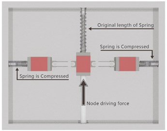
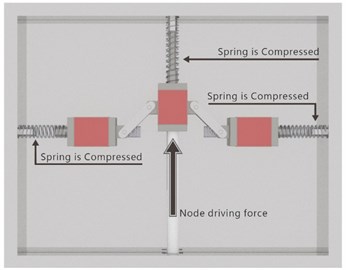
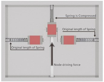
The proposed mechanism consists of two sets of springs, a connecting rod, a rail, and a lightweight electric actuator, shown in Fig. 1.
The change in the force balance state is as follows:
Fig. 1(a): The horizontal spring reaches the maximum compression, while the spring in the vertical direction is in the undeformed state. Although the horizontal spring has a large compression, the forces on both sides offset each other, so the orange push node force is zero.
Fig. 1(b): When springs in the horizontal and vertical directions are deformed, the combined force of the three forces in the middle node are an “unbalanced force”, which must be offset by a push node force.
Fig. 1(c): When the horizontal spring is not deformed and the spring in the vertical direction reaches the maximum compression, the combined force in the middle node is zero, so the push node force, in orange, is zero.
Force balance analysis revealed that if the elasticity coefficient of the horizontal spring is half that of the spring in the vertical direction, then regardless of the angle of the red linkage, the spring force can achieve equilibrium, so the push node force remains zero. Therefore, the output force for changing the spring in the vertical direction does not require any driving force. In other words, the size of the control force of this proposed mechanism can be forceless and arbitrarily changed in ideal conditions. However, it is necessary to consider (1) the elastic coefficient error; (2) the friction of the interior mechanism; and (3) the errors of the length of the mechanism, position and angle of linkage. Therefore, little node force is required.
Fig. 1The principle of the neutral equilibrium mechanism
a)
b)
c)
2.2. Mechanism of the NEM
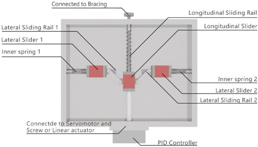
The elasticity coefficient of springs in the vertical direction, which are connected with the bracing, is twice as high as that of the spring in the horizontal direction. When the horizontal spring reaches the maximum compression and the spring in the vertical direction is not deformed, it is in an unforced state. The NEM is designed for a building structure based on the above-mentioned concept. When the control mechanism of the NEM is at 0 degrees, or the horizontal state, then the master spring in the vertical direction is in a forceless state. But the horizontal spring is in the force state and reaches the balance state. When the inside angle of the control mechanism is not 0 degrees, the main spring in the vertical direction begins to receive force, and the horizontal spring is deformed, which changes with changes in the inner angle of the mechanism. Then, when the inner angle is at 90 degrees, the deformation of the spring in the vertical direction is at its maximum and the force taken reaches the maximum force. The horizontal spring deformation and force are both 0. That is, this NEM provides a reverse force with the horizontal deformation of the structure to prevent the deformation of the structure, or to keep the structural deformation within the limits of structural safety. Based on this principle, the original prototype of this NEM was designed, as shown in Fig. 2. The vertical spring of this NEM is connected with the bracing of the structure, and the rod to promote the nodal force is connected with a servo motor or linear actuator. The size of the control force provided by the NEM depends on the dynamic reaction of the NEM during the earthquake. Therefore, the PID Controller and control law of the PID can be applied to determine the reverse force size of the stiffener.
Fig. 2The prototype of this proposed NEM
3. Test of this proposed NEM device
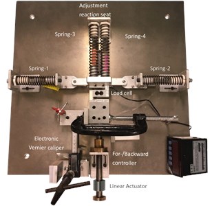
In ideal conditions, this proposed NEM can arbitrarily change the size of the control force without an external driving force. However, this mechanism will be affected by the error of the elasticity coefficient of the mechanism, the friction force within the mechanism, the length of the mechanism, the position, the angle, and other factors, so there will be a little nodal force. Institutional prototypes and experimental devices, shown in Fig. 3, were designed and produced on the basis of Section 2. To verify the feasibility and understand the various effects of this NEM, experimental measurements were conducted for the following purposes: 1. To measure the friction force of the NEM under conditions of both linkage and no linkage; 2. To determine the spring coefficient; 3. To calibrate the ground zero point of the NEM and the thrust block position of spring. This experiment mainly elucidated the following points: 1. Friction force; 2. Elasticity coefficient; 3. Impact of the accuracy error of the components of the mechanism.
3.1. Test model of the prototype of the NEM
The institutional prototype of the NEM was installed on a model as shown in Fig. 3. The springs, Vernier caliper, and propulsion turning wheels were replaced with spring steel, resistive displacement meters, and a detacher to measure the counterforces that elastic steel can provide so that the resistive displacement meter and force reading could achieve sufficient accuracy during the shaking process. A PID controller was installed with this proposed NEM to provide the control law of the PID and determine the counterforce of the stiffener. With the displacement signal as the error signal, the following counterforce of the stiffeners was produced by the push/pull displacement of the micro-actuator. That is, the telescopic amount of the detacher was controlled based on the control theory of the PID. After this experiment, numerical simulation was used to simulate the delay problem of the control force caused by time delay, and the optimal combination of control parameters of the PID.
Fig. 3The proposed prototypes of the NEM and experimental devices
3.2. Experimental methods
For experimental verification, both springs were adjusted to zero displacement, with no compression or gap with the reverse force seat. The experimental mechanism was loaded horizontally into the No. 3 and No. 4 springs, and the No. 1 and No. 2 springs were loaded in the vertical direction, as shown in Fig. 3. To ensure the direction of the friction force, the displacement was guided from less than 0 displacement to 26 mm displacement, and then from 26 mm displacement back to less than 0 displacement. The force reading of displacement of 0 to 25 mm was recorded. The combined force was defined as the need for additional force in addition to the mechanism because of the spring reaction force to achieve balance, so this study defined the combined force measurement as follows:
where: is the combined force and is average load gauge readings for propulsion and draw back.
The push and pull back times are the same and friction force is offset.
Friction was defined as the presence of the mechanism itself and measured by a load gauge. The measurement of frictional forces was defined as follows:
where: is the friction force; is the reading of the load gauge for propulsion.
3.3. Measurement and analysis results
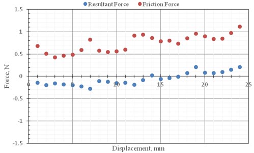
The test and analysis results of the statistical analysis of three measurements are shown in Fig. 4 and 5. The measurement force and node force in the vertical and horizontal spring, shown in Fig. 4, showed that measured forces in the vertical and horizontal springs were almost equal and opposite in direction. The combined force of the nodes, like the force balancing conditions described in the principle of the NEM, required very little node thrust. But in practice, it would be affected by friction within the NEM. The experimental results in Fig. 5 show that there was friction, and the internal friction of this mechanism would affect the joint force of the mechanism node. According to this experimental verification, the control conditions of the NEM are such that the total strength of the inner spring and the total strength of the main control spring must be equal. When the connecting rod angle is zero, the deformation of the main control spring is zero. When the angle of the connecting rod is +/–90 degrees, the deformation of the inner spring is zero. The friction force within the mechanism should be reduced as much as possible, and the use of rolling support can reduce the coefficient of friction to a range of 0.0005 to 0.002. The experimental analysis results revealed that when the control mechanism produced control power of 125 N, the unbalanced force of the control mechanism to be provided was 0.481 N (average values plus three times standard deviation), and its magnification was 260 times. This experiment confirms that the NEM can achieve time and energy efficiency. Therefore, the power demand of this proposed mechanism can be greatly reduced when applied to structural control.
Fig. 4The measurement combined force and node force of springs in the vertical and horizontal direction
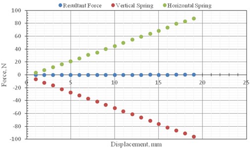
Fig. 5The measurement results of resultant force and friction force
4. Control law of the proposed NEM
4.1. The equation of motion with the NEM
The control function and control law of structure with the NEM when subjected to an external force can be expressed as follows:
where: is mass of the structure; is damping of the structure; is stiffness of the structure; is the external force; is the control force of the NEM.
4.2. Control force of controller of the NEM
The size of the control force of the NEM is determined according to the structural displacement, velocity and acceleration responses. The nodal force of the NEM is controlled by the PID controller. The control law of the PID controller is applied to determine the counter-force of the stiffener, so the displacement signal of the PID is used as an error signal. The following formula can be applied to determine the reaction force of the stiffener and the push/pull displacement amount of the micro-actuator. The control force of the PID is equal to GP*displacement + GI*integration of displacement + GD*velocity + Ga*relative acceleration + GA*absolute acceleration. The control parameters of the PID controller can be divided into the following: Proportional unit P, Integral unit I and differential unit D. Therefore, the control force produced by the NEM can be expressed as follows:
where: is displacement gain; is velocity gain; is integral gain, the adjustment coefficient; is the displacement function of structural control point, where is time.
The various combinations of three gains (, , ) were applied to investigate the seismic proof capability of the NEM. Larger gain indicates better seismic proof capability of the NEM, but it causes control failure. The main cause of control failure is time delay. The time of the occurrence of the control force always lags behind the point in time when the control force should occur; the difference between the two is the time delay. The impact of time delays can be simulated by the program GENDY [14].
4.3. The influence of time delay and the unstable control phenomenon
Many researchers have demonstrated that active control technology provides a pretty good shock absorption effect. In general control theory, it is often assumed that the influence of the time delay on the damping control force is small enough to ignore its effects to simplify the mathematical model. However, the phenomenon of time delay exists between the control force produced by the proposed NEM and the structure, so the influence of this real error on shock absorption efficiency must be discussed. In fact, the main factor affecting the control condition of the NEM is time delay. To investigate the influence of time delay, the effects of time delay and instability are discussed in this study, taking the single degree of freedom rigid body movement as an example. The numerical model of the time delay affecting the NEM is derived as follows:
Let control force be , where is the gain coefficient of displacement. Assume the time delay amount is . Then the equation of the control force can be rewritten as follows:
Thus:
Assume that the time delay amount is very small. Then . Therefore, Eq. (6) can be rewritten as follows:
In this study, is effective damping and is effective stiffness. The ideal state of the NEM is control of the structural displacement to zero under the control of this proposed mechanism. Therefore, when the displacement gain coefficient is very large, the effective stiffness can be raised, but it will reduce the effective damping and even lead to effective damping as a negative value, resulting in the phenomenon of instability.
The proportional unit (P), integral unit (I) and differential unit (D) of the PID controller are composed of the current error, past cumulative error and future error respectively. By adjusting the three coefficients of the PID controller, this controller can meet the design requirements of this proposed NEM. The response of the controller can be expressed by the controller's ability to affect the rate of reaction to errors, the degree of controller overshoot and the degree of system shock.
5. Numerical simulation method
The shock-absorbing reactions of a building with the NEM under seismic force were investigated in this study to explore the shock absorption benefit of the NEM with various control parameters under no time delay and different time delays. Defining the effective interval of control gain for the NEM is conducive to the design of the NEM. The structural displacement responses, relative and absolute structural acceleration responses, base shearing force reaction and output power of the NEM for a one-story shear building without and with the NEM under excitation of earthquake forces were simulated by numerical simulation. The influence of the NEM with time delay on the shock absorption efficiency and the change in the action force produced by the NEM were investigated in this study. Also, the various displacement gain coefficients and velocity gain coefficient changes of the NEM on the shock absorption effect of a building with the NEM were explored under the no time delay and time delay conditions.
5.1. Analysis setting of program
The Vector Finite Elements Method Program GENDYN was employed for the analysis in this study.
Elements #0: Linear spring elements simulated the elastic response force provided by the column of the shear frame and were applied to simulate the spring force between the NEM and the top floor of the main structure.
Elements #1: Linear Springs - Damping parallel elements simulated the elastic-restoring force and damping provided by the column of the shear building. They were also used to simulate the spring force and damping force between the NEM and the top floor of the main structure.
Elements #45: Simulation of the linear control behavior of the NEM. The NEM element set the weighting of its displacement gain factor and velocity gain factor. At the same time, this study also considered condition one, without time delay, and condition two, with time delay.
5.2. Analysis settings
A one-story shear building, shown in Fig. 6, was applied to compare the structural responses of a low building with and without an NEM under excitation of seismic force. The main structure parameters and control parameters of the NEM are described as follows.
When time delay occurs in this proposed NEM, the structural control effect is affected by the amount of time delay, the displacement gain coefficient and the velocity gain coefficient of this NEM. Therefore, to investigate the structural control effect and mechanism reaction of structure with the NEM, a structure installed with this NEM was analyzed under different combinations of displacement gain coefficient and velocity gain coefficient in a wider range, and with various time delay conditions. The main structure parameters of this study were as follows. The bare structure was a one-story shear structure, assuming that the mass of the floor () was 1 ton, the interlayer strength coefficient () was 39.4784 kN⋅sec/m, and the damping coefficient () was 0.2513274 respectively. The height of this shear building was 3.5 m. The modal frequency and damping ratio of the first mode of the bare structure were 1.0 Hz and 0.05 respectively. The analysis range of displacement gain () and velocity gain coefficients () of the NEM were 0–4 and 0-1.591 respectively. This NEM is greatly affected by time delay, so in this study, to ensure that the mechanism could indeed have an effect, the control effect of the time delay coefficient was less than 0.02 seconds and the different velocity gain coefficient and the displacement gain coefficient are discussed. The analysis parameters are shown in Table 1.
Fig. 6The one-story shear building for numerical analysis
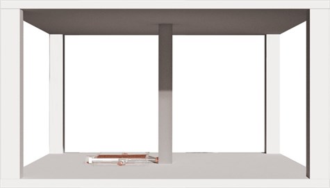
Table 1Analysis settings
Category of analysis parameters | Interval of parameters |
Main structure parameters | Structure type: 1DOF shear building Storey mass: = 1 tn Inter-storey stiffness: = 39.4784176 kN/m Inter-storey damping: = 0.62831853 1st modal frequency: = 1.0 Hz 1st modal damping ratio: = 0.05 |
Control parameters of the NEM (without time delay) | Displacement gain coefficients (): , ,…, , , , ……, Velocity gain coefficients (): , ,…, ,,…, |
Control parameters of the NEM (with time delay) | Displacement gain coefficients (GP): ,,…, , , , ……, Velocity gain coefficients (GD): , , ……, ,,…, Time delay: 0 seconds-0.02 seconds |
Seismic wave | Kobe earthquake record and El Centro record, normalized to 1 G |
The displacement reduction ratio was defined as:
where is the maximum displacement responses of the original structure; is the maximum displacement responses of the structure with the NEM under different displacement gain and velocity gain coefficients.
This displacement ratio is defined to investigate the structural control effect of the structure with the NEM under various displacement gain and velocity gain coefficients.
6. Analysis results and discussion
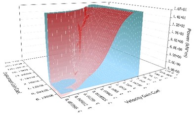
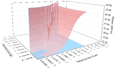
Fig. 7 shows the structural displacement responses of the structure with the NEM under various displacement and velocity gain coefficients under excitation of the Kobe and El Centro seismic records with (1) no time delay; (2) with time delays of 0.001, 0.005, 0.015 and 0.020 seconds respectively. Fig. 8 and 9 display the comparison charts of the unbalanced force of the NEM with the maximum control force of the direct control method under the same control parameters and the maximum output power of the NEM, and the maximum output power of the direct control mechanism under the same control parameters of the structure with the NEM under (1) no time delay; (2) with time delays of 0.001, 0.010 and 0.020 seconds, subjected to the Kobe and El Centro earthquake records.
Fig. 7Structural displacement responses of the structure with the NEM under various time delays and different displacement and velocity gains subjected to various earthquake records
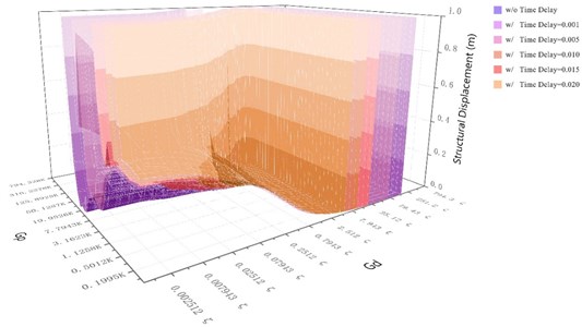
a) Structural displacement responses of the structure with the NEM subjected to the Kobe earthquake record
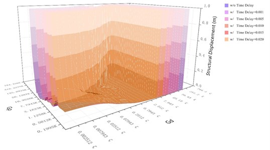
b) Structural displacement responses of the structure with the NEM subjected to the El Centro earthquake record
6.1. Discussion of the structural control effectiveness of the NEM
6.1.1. Analysis of displacement control efficiency
Fig. 7 shows that the structural displacement reduction ratio of the structure with the NEM and without time delay, subjected to the Kobe and El Centro earthquakes, reached more than 70 % for the NEM with velocity gain within 0.07943–158.49 and 0.02512–158.49 respectively. When the velocity gain reached 0.7943 and 0.2512 for the structure with the NEM subjected to the Kobe and El Centro earthquakes, the displacement reduction ratio reached more than 80 %, regardless of the displacement gain. The displacement reduction ratio increased as the velocity gain coefficient increased, and the displacement reduction ratio exceeded 90 %. When the time delay was 0.001 second, the displacement reduction ratio achieved a very good effect for the structure with the NEM subjected to the Kobe earthquake and the El Centro earthquake when the velocity gain coefficients were between 0.07943 and 79.43 and 0.02512 and 79.43 respectively. The interval between the velocity gain and displacement gain was gradually reduced for the structure with the NEM under the increase of time delay condition and subjected to the Kobe earthquake. That is, the velocity gain coefficient was 0.2512 to 15.8481, and the displacement gain factor was less than 158.4887 K for time delay of 0.005 second. When the time delay was 0.01 second, the velocity gain coefficient was 0.2512 to 8.91, the displacement gain factor was less than 50.1287 K, the time delay was 0.015, and the speed gain factor was 0.2512 to 7.9431. The displacement gain factor was less than 25.1142 K. When the time delay was 0.02 second, the velocity gain factor was 0.2512 to 5.0112, and the displacement gain factor was less than 19.9526 K.
Fig. 8The comparison chart of the unbalanced force of the NEM with the maximum control force of the direct control method under the same control parameters subjected to different earthquake records
a) Without time delay
b) With time delay of 0.001 seconds
c) With time delay of 0.01seconds
d) With time delay of 0.02seconds
The interval between the velocity gain coefficient and the displacement gain coefficient was gradually reduced for the structure with the NEM subjected to the El Centro earthquake. That is, when the time delay was 0.005 second, the velocity gain coefficient was 0.0251 to 15.8481, and the displacement gain factor was less than 158.4887 K. When the time delay was 0.01 second, the velocity gain factor was 0.02512 to 8.91, and the displacement gain factor was less than 79.4328 K. When the time delay was 0.015 second, the velocity gain factor was 0.0398 to 7.9431, and the displacement gain factor was less than 25.1142 K. When the time delay was 0.02 second, the velocity gain coefficient was 0.0501 to 5.0112, and the displacement gain factor was less than 19.9526 K. The interval between the velocity gain coefficient and the displacement gain coefficient of the NEM was mainly influenced by the seismic characteristics; i.e., the far-field earthquake and the near-fault earthquake. The analysis results confirmed that NEM could achieve shock absorption by adjusting the velocity gain coefficient and the displacement gain coefficient according to the seismic characteristics.
6.2. The comparison of unbalanced force of the NEM with the maximum output power of the direct control method
Fig. 8(a) and 8(b) show that the highest value of unbalance force was produced by the NEM with a low velocity and displacement gain coefficient. At this time, the imbalance force was large and the displacement control effect was not good. However, with the increase in the displacement gain coefficient under the same velocity gain coefficient, the unbalanced force value of the NEM gradually decreased and the displacement control effect increased.
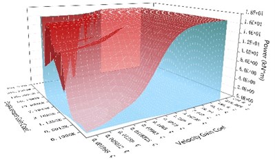
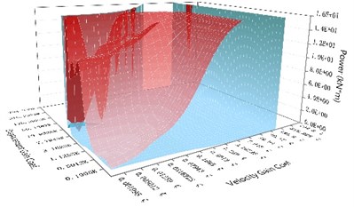
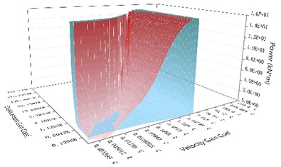
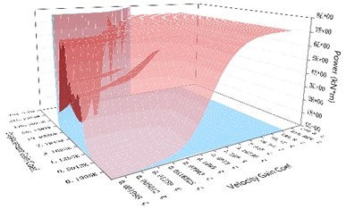
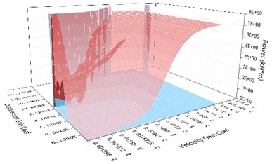
Fig. 9The comparison of the maximum output power of the NEM and the maximum output power of the direct control mechanism under the same control parameters subjected to different earthquake records
a) Without time delay
b) With time delay of 0.001 seconds
c) With time delay of 0.01 seconds
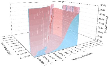
d) With time delay of 0.02 seconds
The maximum control force resulting from the direct control mechanism under the same control parameters changed opposite to the unbalanced force of the NEM. Although the displacement control effect was the same, the maximum control force generated by the direct control mechanism gradually increased. The maximum control force generated by the NEM was only 1/230 that of the direct control mechanism under the same control parameters.
The maximum output power generated by the NEM and the maximum output power of the direct control mechanism are compared in Fig. 9(a) and 9(b). The analysis results showed that the maximum output power of the NEM was only 1/236 that of the direct control mechanism under the same control parameters. However, the maximum output power of the NEM and the direct control mechanism with lower displacement gain and velocity gain were close to 1:1; therefore, the displacement control effect was not good. These two mechanisms did not perform their control effect, so it was not possible to demonstrate the true control effect. When the time delay reached 0.005 seconds, the phenomenon of control failure occurred for both the NEM and the direct control mechanism under the low velocity gain and high displacement gain. The unbalanced force of the NEM was compared to the maximum control force produced by the direct control mechanism with the higher velocity gain coefficient and the higher displacement gain coefficient, and the ratio of the maximum output power of the NEM and the direct control mechanism was close to 1/150. That is, the maximum control force and the maximum output power only required 1/150 of those of the direct control mechanism to achieve the same displacement reduction effect.
Fig. 8(c) and 9(c) show that, when the time delay amount reached 0.010 seconds, the results were similar to those when the time delay amount reached 0.001seconds. But the phenomenon of control failure under the range of the low velocity gain coefficient and the high displacement gain coefficient for both the NEM and the direct control mechanism were enlarged. However, when the time delay was 0.010 seconds, the ratio of the imbalance force of the NEM to the maximum control force produced by the direct control mechanism and the ratio of the maximum output power produced by the NEM to the maximum output power of the direct control mechanism were close to 1/80 respectively. At this time, with the greater time delay, NEM only needed to increase the imbalance force and produce a large output power to achieve the displacement control effect of the direct control mechanism. The gap between those of the NEM and the maximum control force and maximum output power of the direct control mechanism, which could reach the same effective displacement control, was reduced by the increase in the time delay. When the time delay was 0.020 seconds, as shown in Figs. 8(d) and 9(d), the control change variation was the same as that when the time delay was 0.010 seconds or more. The phenomenon of control failure occurred between the NEM and the direct control mechanism under the lower velocity gain coefficient and the high displacement gain coefficient. The ratios of the imbalance force of the NEM to the maximum control force produced by the direct control mechanism and the ratio of the maximum output power produced by the NEM to the maximum output power of the direct control mechanism were close to 1/47 respectively for the fine control effect range with higher velocity gain and higher displacement gain. It was found that the imbalance force and maximum output power of the NEM were greatly affected by the amount of time delay. When the amount of time delay increased gradually for the NEM and the direct control mechanism with the same control parameters, the ratios of the imbalance force of the NEM to the maximum control force produced by the direct control mechanism and the ratio of the maximum output power produced by the NEM to the maximum output power of the direct control mechanism were gradually reduced. The control effect of this proposed NEM will be reduced due to the amount of time delay, so the problem caused by the amount of time delay must be reduced by a sophisticated controller.
7. Conclusions
Analysis results from the past earthquake damages records can be found that the building is often caused damage on the first floor due to insufficient column ratio and wall ratio by the seismic force after the first-floor deformation. The current commonly used method of structural reinforcement will affect the functionality of the original design. Therefore, this study proposes this NEM, which produces control power can reach dozens of times the control force of traditional control mechanisms. The following conclusions were developed through experimental verification and numerical analysis:
1) The control conditions of this proposed NEM were experimentally verified to be as follows: The total combined strength of the inner spring is equal to that of the main control spring. When the angle of the connecting rod is zero, the deformation amount of the main control spring is zero, without structural deformation. When the angle of the connecting rod is +/–90 degrees, the deformation of the inner spring is zero, it reaches to the maximum deformation of NEM.
2) When a building is controlled by this NEM, the power demand of the control mechanism can be significantly reduced. Test results confirmed that the power demand of this NEM, generated by this NEM, requires only 1/260 of the control force of the original device.
3) The control force of the NEM and the maximum control force of the direct control method were compared under the same parameters: (1) With no time delay or time delay of 0.001 seconds, the control force of the NEM with the appropriate gain factor is only 1/230 of the maximum control force of direct control. (2) With time delay of 0.005 seconds, the control force of the NEM is only 1/150 of the maximum control force of direct control. (3) With time delay of 0.010 or 0.020 seconds, the control forces of this mechanism are 1/85 and 1/47 of the maximum control force of direct control respectively. With the increase in the time delay, the ratio of the control force and the maximum control force for direct control gradually decreases.
4) The maximum output power of the NEM and that of the direct control mechanism under the same control parameters were compared, and the analysis results showed the following: (1) The ratio of the maximum output power of the NEM to that of direct control under the same control parameters for no time delay and time delay of 0.001 seconds was 1/236. (2) The ratios of the maximum output power of the NEM to that of direct control under the same control parameters for time delays of 0.005, 0.010, and 0.020 seconds were 1/150, 1/80, and 1/47 respectively. With increases in the time delay, the ratio of the maximum output power of the NEM to that of direct control gradually decreases.
From the experimental and analysis results, the greatest advantage of this proposed NEM is that the NEM, with little control force and small maximum output power, can perform a control effect similar to that of the direct control method under the same control parameters and the same time delay problem. Therefore, this proposed NEM can be used as structural control device of building under excitation of earthquake.
References
-
Housner G. W., Bergman L. A., Caughey T. K., Chassiakos A. G. Structural control: past present and future. Journal of Engineering Mechanics, Vol. 123, Issue 9, 1997, p. 897-971.
-
Chen Y., Cao T., Ma L. Structural vibration passive control and economic analysis of a high-rise building in Beijing. Earthquake Engineering and Engineering Vibration, Vol. 8, Issue 4, 2010, p. 561-568.
-
Zhang Z., Balendra T. Passive control of bilinear hysteretic structures by tuned mass damper for narrow band seismic motions. Engineering Structures, Vol. 54, 2013, p. 103-111.
-
Cacciola P. A., Tombari A. Vibrating barrier: a novel device for the passive control of structures under ground motion. Proceedings of the Royal Society A: Mathematical, Physical and Engineering Sciences, Vol. 471, Issue 2179, 2016, https://doi.org/10.1098/rspa.2015.0075.
-
Shih M. H., Sung W. P. Developing a neutral equilibrium device as dynamic virtual piers for an emergency relief bridge. Journal of Measurements in Engineering, Vol. 6, Issue 4, 2018, p. 289-296.
-
Liu K., Chen L. X., Cai G. P. Active control of a nonlinear and hysteretic building structure with time delay. Structural Engineering and Mechanics, Vol. 40, Issue 3, 2013, p. 431-451.
-
He M., Hu R., Chen L., Chen C. Intelligent active control of a benchmark cable-stayed bridge. Proceedings of the Institution of Civil Engineers - Structures and Buildings, Vol. 168, Issue 12, 2015, p. 890-901.
-
Preumont A., Voltan A., Sangiovanni A., Mokrani B., Alaluf D. Active tendon control of suspension bridges. Smart Structures and Systems, Vol. 18, Issue 1, 2016, p. 31-52.
-
Pourzeynali S., Jooei P. Semi-active control of building structures using variable stiffness device and fuzzy logic. International Journal of Engineering, Transactions A: Basics, Vol. 26, Issue 10, 2013, p. 1169-1182.
-
Shih M. H., Sung W. P. Development of semi-active hydraulic damper as active interaction control device to withstand external excitation. Sadhana – Academy Proceedings in Engineering Science, Vol. 39, Issue 1, 2014, p. 123-128.
-
Uz M. E., Sharafi P. P. Investigation of the Optimal Semi-Active Control Strategies of Adjacent Buildings Connected with Magnetorheological Damper. International Journal of Optimization in Civil Engineering, Vol. 6, Issue 4, 2016, p. 523-547.
-
National Center for Research on Earthquake Engineering, Taiwan, R.O.C., The Investigation of 921 Chi-Chi Earthquake Damages, Reported by NCREE, Taiwan, R.O.C., 1999.
-
Sinotech Engineering Consultants, Ltd. 921 Chi-Chi Earthquake Brief Report. Reported by Sinotech Engineering Consultants, Ltd. Taiwan, R.O.C., 1999.
-
National Chi-Nan University. Multi-functional dynamic Analysis Program of Gendyn 2017, National Chi-Nan University, Taiwan 2017.
About this article

The authors would like to acknowledge the support of Taiwan Ministry of Science and Technology through grant No. MOST 107-2119-M-260-002, MOST 107-2221-E-167-001, and MOST-108-2119-M-260-002.
