Abstract
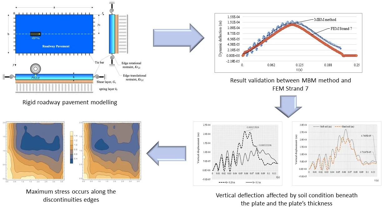
A numerical simulation of a moving vehicle on the rigid roadway pavement with discontinuities is presented in this paper by using the data from one of the toll road segments in Indonesia. The analysis procedure considers the dynamic interaction between the vehicle and the rigid pavement. The rigid roadway pavement is modeled using the Kirchhoff theory of thin slab on elastic foundations. The aim of the numerical analysis is to obtain the vertical deflection in the middle of the slab, to obtain the time history of the slab deflection; and to identify the parameters of the sub-grade that has a significant effect on the dynamic response of the rigid roadway pavement. The equations of motion are derived in the form of partial differential equations of the fourth order. The mode shapes of the slab deflection are determined from the method of first and the second auxiliary equations of Levy-type in the - and -directions, which is also known as the Modified Bolotin Method (MBM). The equations of motion are solved numerically by using Mathematica. The influence of various parameters including the peak vertical velocity due to the moving vehicle, the stiffness of subgrade, the slab thickness and the road profile to the dynamic behavior of the rigid roadway pavement are studied in detail. The results obtained from the plate computing model in this paper are then compared and analyzed with the results computed using the finite element method by Strand 7 to show that the solution obtained using the MBM method is accurate. In addition, the paper aims to show that the thickness of the plate plays a significant role in the distribution of the bending stresses in plate discontinuities and is necessary for engineers to design rigid roadway pavements.
Highlights
- Rigid roadway pavement is modelled as an orthotropic plate with discontinuities that are represented by translational restraints and rotational restrains along the edges.
- The modified Bolotin method can be used as the analytical method to solve the dynamic behavior of rigid roadway pavements.
- The vertical deflection of the rigid roadway pavement is affected by the plate thickness, the soil condition underneath the plate region, and the velocity of the movement vehicle.
- The maximum stress distribution is affected by the plate thickness and occurs along the discontinuous edge.
1. Introduction
In the design of rigid roadway pavements, designers have relied on the Westergaard equation [1] which assumes that the pavement has an infinite length and static loading condition as well as no longitudinal and transverse displacements occurring along the joint within the pavement.
With the advancement of computer software applications and the finite element method of structural analysis, the response of rigid roadway pavement subjected to a moving load is analyzed by assuming the rigid pavement as a discontinuous slab, which are joined to an adjacent slab by load transfer devices [2-4]. Kruketi et al. in 1992 studied the dynamic analysis of rigid airport pavements with discontinuities. Algorithms were developed to solve the moving mass problem, where the effects of the vehicle’s mass inertia were considered in determining the dynamic response of pavements to moving loads. The discontinuities in the pavement were represented by vertical spring elements connecting two nodes having the same global coordinates in the finite element mesh [5].
There has been lots of research related to the solution of vehicle–road interaction problems. Alisjahbana and Wangsadinata in 2015 studied the dynamic response of rigid roadway pavement sitting on the Pasternak foundation model subjected to moving traffic load. In this work, the moving traffic load is modeled as a harmonic load that travels with the constant velocity v0 along the -axis, [6]. Later in 2016, Gibigaye et al studied the dynamic response of a rigid pavement plate based on an inertial soil by using the Modified Bolotin Method. The result shows the possible economic gain when taking into account the inertia of soil in the pavement dynamic design [7]. However, these results do not cover the internal forces and stress distribution occurring along the discontinuities that may affect the design of the rigid roadway pavements.
A numerical simulation of moving load on concrete pavements was studied by Lajcakova and Melcer in 2015. In this study, the influences of velocity, subgrade stiffness, slab thickness and road profile to the deflections of the slab were analyzed. In addition, by using the FEM analysis, Lajvakova and Melcer concluded that contact forces increased with the velocity of the vehicle motion [8].
This study presents a numerical simulation of the dynamic deflection and the stress distribution of rigid roadway pavements with discontinuities subjected to a moving vehicle by using the Modified Bolotin Method. Furthermore, this study also includes the effects of the soil conditions underneath the rigid roadway pavements, the velocity and the angular velocity of a vehicle to the dynamic response of the rigid roadway pavement. This research is useful for rigid roadway pavement design, especially for its dynamic analysis.
2. Computational model of road slab
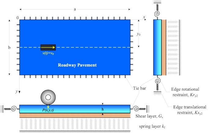
The computational model of rigid roadway pavement will be considered as a rigid roadway pavement on the Pasternak elastics foundation model. The computational model of rigid roadway pavement is based on the Kirchhoff theory of thin plates [6] as described by Eq. (1):
Fig. 1Model of rigid roadway pavement on Pasternak elastic foundation model under a moving vehicle
The vertical displacement of the slab will be expressed as the product of two functions:
The function represents the spatial function that is dependent only on the coordinates , The function represents the unknown function and is dependent on the time . The function is determined from the solutions of the first and the second equation of the Levy type problem.
The meaning of the remaining symbols are as follows: is the slab stiffness in the -direction, is the torsional rigidity of the slab, is the slab stiffness in the -direction, is the spring modulus of the foundation, is the shear modulus of the foundation, is the mass density of the surface, is the damping ratio of the surface, and is the moving vehicle load.
The moving vehicle is modeled as a harmonic load with constant amplitude that can be expressed as [6, 9]:
where is the maximum amplitude of the moving vehicle, is the coefficient that depends on the type of the vehicle; is the circular frequency of the moving vehicle; is the speed of the vehicle; and is the acceleration. The position of the moving vehicle at any time can be expressed by using the Dirac delta function as described in Eq. (3).
Eqs. (1) and (2) are the fourth order partial differential equation governing the flexural vibrations of a slab under the moving vehicle load. The boundary conditions of the slab with discontinuities are given by:
The constraints of the elastic vertical support and rotation due to the existence of dowels and tie bars are characterized by and , respectively. The index 1, 2, 3, 4 stems for 0, and 0, , where the index notation of the Poisson's ratio shows the perpendicular direction of , and is the shear modulus of the orthotropic slab.
3. Solution procedure for dynamic equations
The dynamic response to a moving vehicle of the orthotropic rigid roadway pavement with discontinuities resting on a Pasternak foundation and subjected to boundary conditions according to Eqs. (4) and (5) is carried out in this section. The generalized solution of the spatial function is defined as the multiplication of the function and as follows [10]:
where , …, and , …, are constants which are determined using the boundary conditions according to Eqs. (4) and (5).
Applying the boundary conditions along 0 and , the results in the linear algebra equation in terms of , are obtained as follows:
Substituting the spatial function according to Eq. (6) into the boundary conditions along 0 and of Eqs. (4) and (5), results in the linear algebra equation in terms of are obtained as follows:
Details of the matrix elements in Eqs. (7) and (8) can be seen in Appendix.
The eigenvalues of the system are the roots of the characteristic determinant equation that can be solved simultaneously from Eqs. (7) and (8):
where and are the real numbers that can be solved from the auxiliary Levy‘s type problem [9].
The generalized solution of the temporal problem is given by integrating Eq. (1) in both sides along the edges of the rigid pavement and applying the orthogonality of and according to Eq. (6), which results in:
Thus, the general solution of the associated moving vehicle of the rigid roadway pavement with discontinued edges are obtained by multiplying the solution of the temporal function Eq. (10) by Eq. (6).
4. Results and discussion
In this paper, a rigid roadway pavement segment of a toll road in Indonesia was studied. The segment was modeled with discontinuities and subjected to traffic load traveling with a non-constant speed. The numerical values for the fundamental natural frequencies were calculated using two transcendental equations of the Levy type problem in the x and y-direction of the rigid roadway pavement.
The material properties for vibration behavior of the system and the boundary conditions used for computation purposes by taking into account the existence of the dowel and tie bar along the edges are presented in Appendix.
To verify the mathematical model used in the analytical solution, the software Strand 7 is used to compare the midspan deflection of the system subjected to a vehicle traveling with a constant velocity 16.67 m/s to the midspan deflection of the system calculated by the modified Bolotin Method. For this purpose, it is assumed that 80 kN, 2 m/s2 and 100 rad/s (955 rpm). These values correspond to typical trucks operated in Indonesia roadways. The discrepancy of maximum deflection at mid-span of the plate by using the Modified Bolotin Method (MBM) to the FEM by Strand 7 for several models can be seen in Table 1.
Table 1Discrepancy of mid-span dynamic deflection of rigid roadway pavement MBM method vs FEM using stand 7
Model | Dynamic deflection (m) | % Discrepancy | |
MBM method | FEM strand 7 | ||
1 – Orthotropic with no tie bar | 9.13818.10-5 | 9.40086.10-5 | 2.79 |
2 – Orthotropic with tie-bar | 1.24709.10-4 | 1.30101.10-4 | 4.14 |
3 – Orthotropic with tie-bar on Pasternak foundation model | 1.36627.10-5 | 1.30465.10-5 | 4.51 |
Fig. 2Dynamic deflection time history using MBM method and FEM Strand 7 for model 3
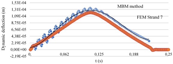
Fig. 33D dynamic deflection of rigid roadway pavement segment using strand 7 for model 3
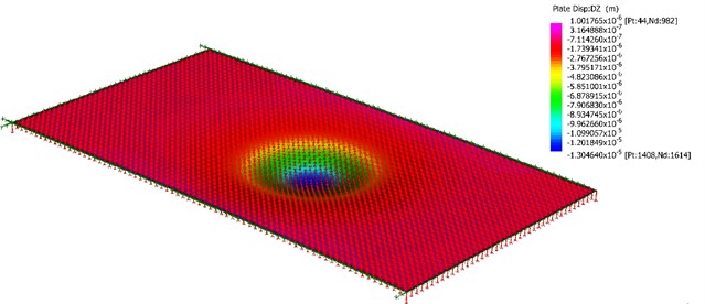
Table 1 shows the dynamic deflection at the mid-span for three different models of the orthotropic plate subjected to the constant load moving with a constant velocity of 16.67 m/s.
Model 1 is an orthotropic plate with simply supported boundary condition along its edges, and no elastic foundation beneath the plate. This model is used to calculate the response of the continuous plate without elastic supports beneath the plate. Model 2 is an orthotropic plate without elastic supports and is restrained by tie bars only along its edges. On the other hand, model 3 is an orthotropic plate with elastic supports and is restrained by tie bars along its edges. Since there are no elastic supports beneath the plate of model 2, the maximum dynamic deflection at the mid-span of model 2 is very large compared to model 3. From the three models, model 3 is the most accurate model to calculate the dynamic behavior of rigid roadway pavements subjected to vehicle loads.
By solving the problem analytically using the MBM method, the discrepancies of the dynamic deflection at the mid-span of the plate for model 1 is 2.79 % lower, model 2 is 4.14 % lower, and model 3 is 4.51 % higher than the one calculated using the FEM Strand 7. The values of discrepancy between MBM and FEM Strand 7 varies between 2.79 % to 4.51 %, which shows that the MBM method accurately solve the dynamic problem of orthotropic plates with different boundary conditions along its edges.
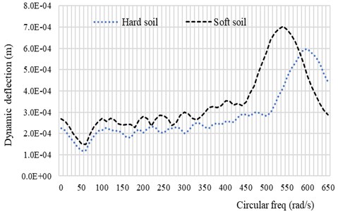
Fig. 4 and Fig. 5 shows the behavior of the rigid roadway pavement on the Pasternak foundation model subjected to the moving vehicle. The dynamic response of the system depends on the soil conditions as well as on the speed and the circular frequency of the system. The absolute dynamic deflection of the system increases as the speed of the vehicle approaches the critical speed of the system. This behavior can also be seen when the circular frequency of the vehicle approaches the first natural frequency of the system as shown in Fig. 5.
Fig. 4Response spectra of the system with soft soil and hard soil conditions as function of vehicle speed
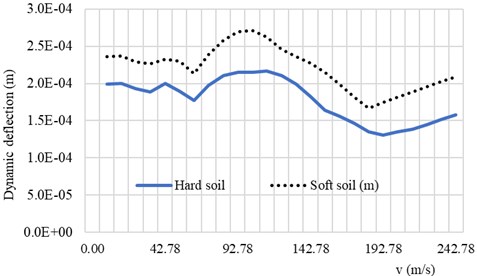
Fig. 5Dynamic deflection response spectra of the system with soft soil and hard soil conditions as function of circular vehicle frequency
To demonstrate the dynamic deflection of the system subjected to the vehicle velocity 30.55 m/s, and 2 m/s2, the time history of the system is computed in Fig. 6. It can be seen from Fig. 6 that the dynamic deflection of the system is also influenced by the soil condition beneath it. The discontinuity condition at the edge of the plate due to the existence of the tie-rod in the form of vertical displacement is also influenced by the soil condition. The discrepancy of the vertical displacement between the soft soil condition and the hard soil condition for the parameters used in this paper is about 21.26 %. This result shows that when the rigid roadway pavement rests on soft soil foundation, most of the pavement is affected by the load while the resonance load frequency is small.
Fig. 7 and Fig. 8 shows the influence of the plate thickness on the dynamic response of the system subjected to the vehicle load. When the plate thickness is increased by 15.3 %, the maximum dynamic deflection of the system reduces significantly by 45 %. Fig. 8 shows the maximum stress distributions over the rigid roadway pavement at 0.02 s when the vehicle moves from the left to the right of the plate. It is shown from Fig. 8. that the values of the maximum stresses along the discontinuities decrease as the plate thickness increases. From the numerical computation above, it is now possible to carry out the general deduction. When the stiffness of the rigid pavement plate is increased, the vertical displacement and the maximum stress over the plate region is decreased.
Fig. 6Vertical displacement time history of the rigid roadway pavement with vehicle speed of v0= 30.55 m/s, acc= 2 m/s2 and ω= 100 rad/s
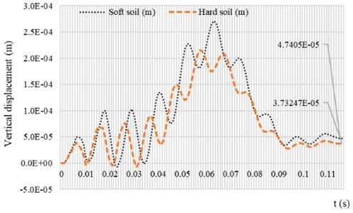
Fig. 7Vertical displacement time history of the rigid roadway pavement for two different values of h with soft soil condition. Data of moving vehicle are: v0= 30.55 m/s, acc= 2 m/s2 and ω= 100 rad/s
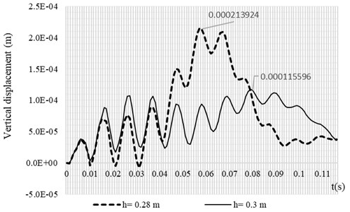
Fig. 8Maximum stress distribution of rigid roadway pavement for two different values of h with soft soil condition. Data of moving vehicle are: v0= 30.55 m/s, acc= 2 m/s2 and ω= 100 rad/s, t= 0.02 s
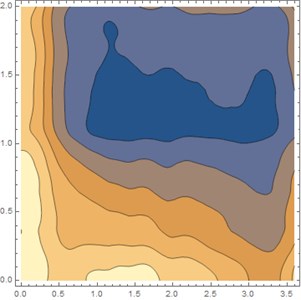
a) 0.26 m
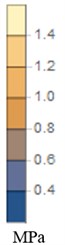
b) 0.30 m
5. Conclusions
The numerical simulation of a moving vehicle on a rigid roadway pavement with discontinuities based on the Modified Bolotin Method has been investigated. The pavement model is modeled as discrete plates joined at the discontinuities by vertical springs representing the load transfer devices and supported by a shear layer and uniformly distributed springs representing the Pasternak elastics foundation. In this paper, the influence of the vehicle velocity, circular vehicle frequency, soil conditions beneath the plate and the plate stiffness were considered.
The main conclusions of this study are as follows:
1) The vertical plate deflections at the mid-span increase with the velocity of the vehicle until reaching critical value. It then decreases after reaching the critical velocity. This condition also occurs when the circular frequency of the vehicle reaches the first natural frequency of the rigid roadway pavement.
2) The influence of the plate stiffness has the opposite tendency in comparison with the influence of the velocity and the circular frequency of the vehicle motion. The maximum vertical deflection of the plate decreases with the increase of the plate stiffness. This condition is valid for all soil conditions beneath the plate.
3) The vertical displacement of the plate along the discontinuity is affected by the soil condition. When the rigid roadway pavement is supported by soft soil conditions, the efficiency of the dowel as a load transfer device should be accurately specified compared to hard soil conditions to avoid the deterioration of the road profile.
4) The maximum stress distribution within the plate region is affected by the plate thickness. The maximum stress decreases when the plate thickness increases. The parametric study shows that the maximum stress occurs along the discontinuous edge, which means that the analysis for the stresses near joint locations should become the main consideration for engineers.
References
-
Westergaard H. M. Stresses in concrete pavements computed by theoretical analysis. Transportation Research Record, Vol. 7, Issue 2, 1926, p. 25-35.
-
Chou Y. T. Structural Analysis Computer Programs for Rigid Multi Component Pavements with Discontinuities-WESLIQID and WESLAYER. Tech. Reports 1, 2, and 3, US Army Engineer Waterways Station, Vicksburg, Miss, 1981.
-
Huang Y. H., Wang S. T. Finite element analysis of concrete slabs and its implications for rigid pavement design. 52nd Annual Meeting of the Highway Research Board, Vol. 446, 1973, p. 55-69.
-
Huang Y. H. Finite element analysis of slabs on elastic solids. Journal of Transportation Engineering, Vol. 100, Issue 2, 1974, p. 403-416.
-
Kukreti A. R., Taheri M. R., Ledesma R. H. Dynamic analysis of rigid pavements with discontinuities. Journal of Transportation Engineering, Vol. 118, Issue 3, 1992, p. 341-360.
-
Alisjahbana S. W., Wangsadinata W. Dynamic response of rigid roadway pavement under moving traffic loads. The 8th International Structural Engineering and Construction Conference, Sydney, Australia, 2015.
-
Gibigaye M., Yabi C. P., Alloba I. E. Dynamic response of a rigid pavement plate based on an inertial soil. International Scholarly Research Notices, Vol. 2016, 2016, p. 1-9.
-
Lajcakova G., Melcer J. Numerical simulation of moving load on concrete pavements. Transport and Telecommunication, Vol. 16, Issue 2, 2015, p. 145-157.
-
Alisjahbana S., Wangsadinata W. Dynamic analysis of rigid roadway pavement under moving traffic loads with variable velocity. Interaction and Multiscale Mechanics, Vol. 5, Issue 2, 2012, p. 105-114.
-
Alisjahbana S. W., Safrilah, Putra J. C. P., Asmi A., Alisjahbana I., Kiryu S., Gan B. S. Dynamic response of pavement plates to the positive and negative phases of the Friedlander load. Strength of Materials, Vol. 50, Issue 5, 2018, p. 702-710.
About this article

This research is supported in part by the Director General of Research and Development Center, Ministry of Research, Technology and Higher Education of the Republic of Indonesia as per contract No. 11/AKM/PNT/2019, to whom the authors are grateful. The authors are also very thankful to anonymous reviewers for their very helpful suggestions and comments, which improve the content and presentation of the paper.
Prof Sofia W. Alisjahbana was responsible for analytical formulations by using Modified Bolotin Method, method of variation of variables, computational mechanics and software engineering by Mathematica. Irene Alisjahbana helped with the analytical formulations by using finite element analysis. Safrilah was responsible for finding the mathematical model for vehicle load in Indonesia toll road, as well as finding the mathematics model of the boundary conditions of the toll road in Indonesia. Jouvan Chandra Putra’s responsibility was to simulate the dynamic response of the plate as well as solving the partial differential equations. Dr. Ade Asmi’s responsibility was to analyze the traffic load in Indonesia toll road as well as to analyze the boundary conditions of the rigid roadway pavement. Prof. Buntara S. Gan helped with the computational mechanics and software engineering (Strand 7). He has contributed in conducting the verification of the analytical formulations by using finite element analyses.
