Abstract
The maximum displacement in a soil nail bond system considering the pull-out, overburden load and grouting pressure effects has been evaluated. The Pull-out tests were carried out in five sites that located in Tehran, Iran. Moreover, additional pull-out test data from South Korea is considered. The displacement of the nailing system due to gravity and pressure grouting has been measured. Based on achieved data, four practical relationships between bound strength and pull-out displacements are developed. The parameters overburden load, grouting pressure, borehole diameter, moisture content and soil’s strength parameters have been chosen as the major inputs for the relationships. The correlation coefficients of the linear relationship range have been achieved between 0.89 and 0.99. While by using the multi-layer neural network for estimating it has been illustrated approximately 0.95.
1. Introduction
The soil nailing system is one of the common methods to stabilize soil wall for deep excavated areas and surface of slopes [1, 2]. Low costing, no dependency on a lot of apparatus and effortless running are the significant advantages of the nailing system [3]. However, in some special cases of soil conditions, site geometry or loading, the nailing system may not be affordable or efficient [1]. The nailing system clearly has an increased activity in the soil shear strength [4].
A common nailing system has the steel bars with diameters between 25-40 mm are prevalent to use as reinforcing elements [5, 6]. Rotary drilling, driven casing, augured and jet grouting are most widespread for coring between 95 to 120 mm diameters [1, 2]. Moreover, the length of drilled borehole directly related to bar length and slope or excavation height [1, 2]. The set of the borehole and its steel bar should be full of cement grouting or soft concrete [4, 7].
Most of the nails have been placed by using gravity pressure grouting. Occasionally, to increase bound strength the pressure-grouting technique has been done for nailing installation that grouting pressure most of the times would be considered between 300-1000 kPa. While this technic has been demanded additional equipment such as pump, packer system and instrument tools. Furthermore, higher quality control compares with regular gravity pressure soil nails is necessary in case of pressure grouting. In addition, using pressure grouting system would be able to improve the grouting formation in the borehole [7], expand the diameter of the borehole and reducing the total number of used nails.
There is no a direct relationship to approximate the bound strength due to effective parameters and nailing system displacement and just in site experimental work such as pull-out would be used. A substantial method to estimate the bound strength is presented in FHWA [1, 2]. The numerous of last studies have assessed the pull-out conduct of gravity and pressure grouting nailing by using numerical simulation and laboratory or field tests [4, 6]. Some of the previous research on bound strength and nailing system displacement are [8-11].
The current work has been focused on to develop new practical relationships to estimate the outcome displacement for nailing system which may be resulted during pull-out test considering soil conditions and site loading. Both cases of pressured and gravity grouting conditions would be considered. The base of input results has been generated by using the in-site pull-outs test and previous literature. Furthermore, linear regression is used to developing the relationships, while the multi-layer neural network has been used for verification.
2. Material and methods
2.1. Experimental data and filed work
Twenty different pull-out test has been conducted in five different place in Tehran, Iran. The places Tejrish, Artesh and Sayyad shirazi Highway areas are placed in the north and northeast of Tehran. While Sadeghiye and Shahrak gharb areas are located in west and north-west of Tehran respectively. Additional pull-out the data have been taken from [11]. Information for the data type for each of sites has been presented in Table 1.
Table 1The site name, location and the data types
Site No. | Name | Country | Type of data |
1 | Tajrish | Iran | Pull-out |
2 | Artesh | Iran | Pull-out |
3 | Sayyad shirazi Highway | Iran | Pull-out |
4 | Sadeghiye | Iran | Pull-out |
5 | Sharak gharb | Iran | Pull-out |
6 | Pusan | South Korea | Pull-out- Numerical |
7 | Gyeonggi | South Korea | Pull-out- Numerical |
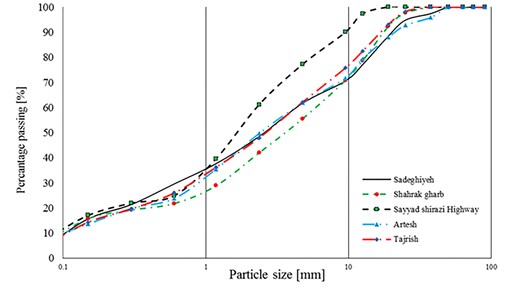
The mechanical properties of soil such as cohesion, friction angle, elastic modulus, moisture content and percentage of coarse- and fine-grained soils were determined in the laboratory for Kharazmi university of Iran, while the data analysis and finalized result is performed in the Institute of geotechnical engineering (IGT) in Austria. The disturbed samples were used to determine the soil physical properties like particle size distribution. Test method for Particle-Size analysis of was succeeded according to the standard of [12]. The particle size graph shows in Fig. 1.
Fig. 1Soil particle size dispersion graph for Tehran province sites
To evaluate the mechanical properties of the soil, the direct shear test is performed in the mentioned laboratory. The values of soil cohesion and fraction angle have been evaluated according to [13]. Standard method [14, 15] are also used to assess the moisture content and soil density respectively. The plate load test (PLT) has been performed to estimate the attribute values of soil elastic modulus (Fig. 2). Hence it is conducted regarding the standard method [16]. The achieved results of all laboratory and filed experimental works are reported in Table 2.
Fig. 2In hole plate load test experiment to evaluate the in-situ elastic modulus
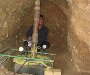
Table 2The mechanical properties of soil in different evaluated sites
Site No. | [Degree] | [kPa] | Elastic modulus [kPa] | [kN/m2] | Moisture content [%] | PI | LL | Ʋ |
1 | 35 | 9 | 60000 | 20,6 | 9,52 | 7,5 | 25,5 | 0,32 |
2 | 33 | 49 | 35000 | 20 | 7,4 | 14,43 | 40 | 0,35 |
*3 (4 m) | 45 | 2 | 35000 | 20 | 10,54 | 6,6 | 34,7 | 0,3 |
*3 (8 m) | 45 | 1 | 48000 | 20 | 11,5 | 6,6 | 30 | 0,3 |
4 | 38 | 12 | 80000 | 21 | 7,6 | 4 | 23,8 | 0,33 |
5 | 33 | 7 | 65000 | 20,2 | 9,24 | 14,9 | 34,7 | 0,32 |
6 | 31 | 15,88 | 33320 | 16,66 | N.D** | N.D | N.D | 0,33 |
7 | 42 | 6 | 34370 | 17,67 | N.D | N.D | N.D | 0,3 |
* Depth of measurement ** Non-detected | ||||||||
The properties of nail bars that have been used in current study tests presented in Table 3. Two sizes of steel bars have been chosen 40 and 32 mm for both sites for Tehran and South Korea respectively (Fig. 3). The unbound length for all test is considered 1m and the length bounded skin has been reported in Table 3. In addition, the maximum grouting pressure in current work is chosen 200 and 500 kPa. The overburden load as the soil’s column height has been selected both 2 and 8 meters (Fig. 4). Furthermore, the diameter of nailing hole is considered 110 mm and 105 mm for experimental and reviewing work respectively.
Table 3The nail rebar properties that used in this study
Site No. | [mm] | Elastic modulus [kPa] | Bond length [m] | Unbound length [m] | Max pressure [kPa] | Hole diameter [mm] | Overburden [m] |
1 | 40 | 1,20E+10 | 3 | 1 | 200 | 110 | 4 and 8 |
2 | 40 | 1,20E+10 | 3 | 1 | 200 | 110 | 4 and 8 |
3 | 40 | 1,20E+10 | 3 | 1 | 200 | 110 | 4 and 8 |
4 | 40 | 1,20E+10 | 3 | 1 | 200 | 110 | 4 and 8 |
5 | 40 | 1,20E+10 | 3 | 1 | 200 | 110 | 4 and 8 |
6 | 32 | 2,00E+10 | 3 | 1 | 500 | 105 | 2 |
7 | 32 | 2,00E+10 | 3 | 1 | 500 | 105 | 2 |
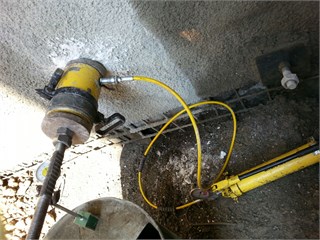
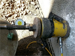
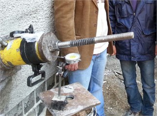
The standard pull-out test due to a Federal Highway Administration (FHWA) report, has been conducted in mentioned sites on the non-structural nails for this destructive tests. Due to a FHWA report, a period of 7 days is needed to get the desired physical strength after grouting. In order to perform the test, an Enerpac 600 kN cylindrical hydraulic jack was used. The pressure gauge has been calibrated according to ISO 143904-Ukas (England) (Ukas, 2006). The parts of the jack and its displacement and pressure gauge have been shown in Fig. 5.
Fig. 3The steel bar that have been used in Tehran
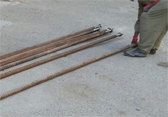
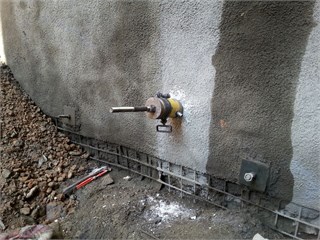
Fig. 4The facing for the nailed wall in site of Pasdaran, Tehran province
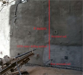
Fig. 5Pull-out test by using Enerpac 600 jack to pulling the rebar
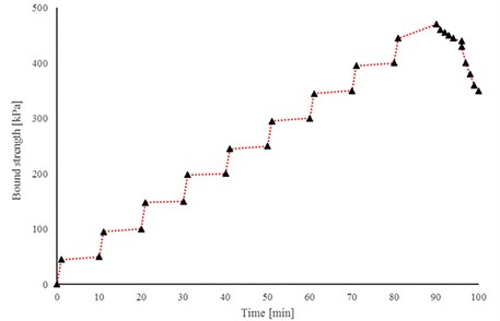
The test has been carried out with constant force with 10 min rest time. During each stage of the experiment, the value of force increment has been increased 50 kN. The force-time diagram related the site of Sayad Shirazi Highway is shown in Fig. 6.
Fig. 6The Force-Time diagram for Sayad Shirazi Highway site considering 10 min rest
Results of pull-out tests in due to two different type of gravity and pressure injection are presented in Fig. 8. It is observed that the maximum bound strength in case of gravity pressure would have occurred in both of Tajrish and Artesh sites that are located in the north of Tehran province. While bound strength for Pussan and Goenngy have shown higher range in the comparison with the mentioned sites in Tehran. In a detailed comparison, it is observed that some factors such as the soil mechanical properties, the hole diameter and the elastic modulus of bars would be affected by the bond strength.
In addition, the results of pressured injection pull out the test is reported on the right side of Fig. 7. The graph shows that in the case of pressure grouting, the response of bound strength for a nailing system significantly has been changed. In addition, it is observed that in case of pressure grouting, the response of bound strength in the site of Sadeghiyeh has been increased more than Tajrish site. However, once again both cases of Geoyongy and pussan are have been shown the highest response of shear bond strength.
Fig. 7Results of pull-out test of site: a) gravity grouting pressure, b) high pressure grouting pressure
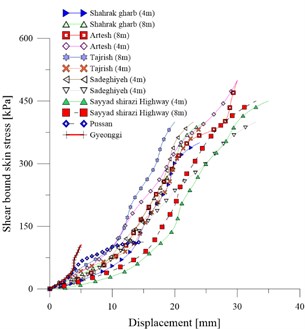
a)
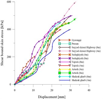
b)
2.2. Statistically analysis
The primary statistical analysis to determine the values of mean, median, standard errors and variance of soil domain has performed and its results are reported in Table 4. 223 different data have been extracted out from pull-out tests to use as input for future development.
Table 4Result of primary statistically analysis for evaluated soil
Statistically analysis type | Moisture content [%] | PI | LL | Elastic modulus [kN/m2] | [kN/m3] | [kN/m2] | |||
Mean | 9,07 | 9,17 | 32,39 | 5,25E+04 | 19,90 | 36,76 | 15,84 | 6,86 | 0,32 |
Median | 9,24 | 7,50 | 34,70 | 4,80E+04 | 20,00 | 35,00 | 9,00 | 5,00 | 0,32 |
Std. error of mean | 0,09 | 0,28 | 0,39 | 1,15E+03 | 0,08 | 0,31 | 1,12 | 0,29 | 0,00 |
Minimum | 7,40 | 4,00 | 23,80 | 3,33E+04 | 16,66 | 31,00 | 1,00 | 3,00 | 0,30 |
Maximum | 10,54 | 14,90 | 40,00 | 8,00E+04 | 21,00 | 45,00 | 49,00 | 15,00 | 0,35 |
Range | 3,14 | 10,90 | 16,20 | 4,67E+04 | 4,34 | 14,00 | 48,00 | 12,00 | 0,05 |
Std. Deviation | 1,27 | 4,21 | 5,83 | 1,72E+04 | 1,18 | 4,67 | 16,69 | 4,31 | 0,02 |
Variance | 1,62 | 17,69 | 33,98 | 2,97E+08 | 1,39 | 21,77 | 278,70 | 18,60 | 0,00 |
To assess the correlation for each impressive factor on the shear strength and its relationship with soil nailing system displacement, a Pearson correlation (PC) test to determine the coefficient correlation has been conducted. Results of PC analysis showed that, the displacement values (Dis) strongly depended on the rate of moisture content (MC), soil specific weight (), bounded length of nails bar (BL), pull-out shear stress (PSS), nail elastic modulus (NEM), hole diameter (), grouting pressure (G.P) and overburdens length (OB). A number of parameters have had negative and others have had positive effects on the nailed system displacement. Furthermore, it is observed that PSS, BL, , NEM, OB, GP, and MC had the highest effect on the Dis respectively. The finalised PC values have been reported in Table 5.
Table 5Results of Pearson correlation for soil measured data
MC | LL | SEM | Ø | B.L | PSS | Dis | NEM | G.P | OB | ||||||
MC | 1 | 0.035 | –.310 | –.525 | .466 | 0.718 | –.475 | –.190 | –.136 | .475 | .533 | –.475 | –.788 | .201 | –.322 |
PI | –.298 | .708 | –.282 | 0.039 | –.589 | .556 | .250 | 0.114 | 0.114 | –.250 | –.652 | .250 | .427 | –0.105 | .175 |
LL | 1 | –.792 | –.433 | –0.126 | .529 | –.163 | 0.017 | 0.069 | .163 | –0.126 | –.163 | .213 | 0.059 | –0.11 | |
SEM | 1 | .654 | –0.078 | –.408 | .443 | 0.073 | 0.044 | –.443 | –0.119 | .443 | –0.058 | –.172 | .357 | ||
1 | 0.05 | 0.007 | .939 | .287 | .291 | –.939 | –0.12 | .939 | 0.055 | –.396 | .649 | ||||
Ø | 1 | –.536 | –0.008 | –0.006 | 0.058 | 0.008 | .759 | –0.008 | –.787 | 0.005 | –0.002 | ||||
1 | 0.128 | 0.124 | 0.083 | –0.128 | –.507 | 0.128 | .864 | –0.066 | 0.078 | ||||||
B.L | 1 | .325 | .371 | –1.000 | –0.068 | 1.000 | 0.121 | –.433 | .693 | ||||||
PSS | 1 | –.926 | –.325 | –0.023 | .325 | 0.09 | –0.1 | .259 | |||||||
Dis | 1 | .371 | 0.104 | .371 | 0.047 | .241 | .246 | ||||||||
NEM | 1 | 0.068 | –1.000 | –0.121 | .433 | –.693 | |||||||||
1 | –0.068 | –.542 | 0.006 | –0.043 | |||||||||||
1 | 0.121 | –.433 | .693 | ||||||||||||
1 | –0.065 | 0.077 | |||||||||||||
G.P | 1 | –.288 | |||||||||||||
OB | 1 |
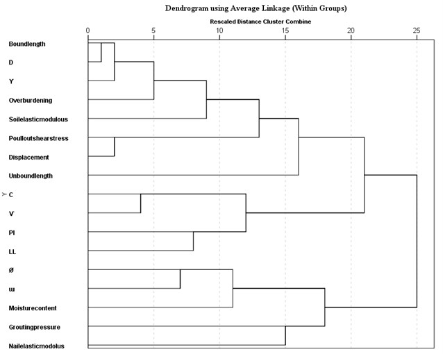
To complete the statistical analysis a hierarchical clustering (HCA) has been performed. The results of hierarchical clustering usually would be presented in a dendrogram. The group dendrogram for impressive factors illustrated in Fig. 8. It is observed that the relationship between the set of moisture content and pressure grout is more considerable than the relationship between the set of soil specific weight, hole diameter, and bound length. Besides, the dendrogram truly has been shown that the poison ratio would be depended to cohesion and dilation angle has a meaningful relationship with soil friction angle.
Fig. 8The HCA dendrogram for nailing system specific groups
2.3. Principal assumptions
According to the results of PC and HCA analysis, the integral effective parameters for Disp had been selected. Hence, four different sets of input parameters are generated as the models in current work. A general and three special models (model 1 to model 3) to develop new practical relationships for estimating the “Disp.” have been considered. The constant condition for bounded length also had been considered in the current work. While the effects of G.P in case of the general model has been neglected. To consider the effects of G.P on the Disp, the model 1 have been generated. Also, other relationships that have focused to reduce inputs were also made as models 2 and 3. The effects of G.P neglected in model 2 while it has been considered in model 3. The input parameters for all of the developed models are shown in Table 6.
Table 6Input parameters for each of generated model to develop new relations
General model | Model 1 | Model 2 | Model 3 |
M.C | M.C | M.C | M.C |
PI | |||
S.E.M | N.E.M | Ø | Ø |
Ø | |||
G.P | C | P.S.S | P.S.S |
P.S.S | P.S.S | O.B | O.B |
O.B | O.B | D | |
G.P | |||
G.P | |||
N.E.M | |||
Strain |
3. Results and discussions
The extracted results of displacement, bond strength and total strain for the nailing system have been evaluated by using the Kriging method. The total strain is consisting of elastic strain for steel bar, elastic strain for cement grout, elastic strain for soil and plastic strain. The primary estimation of the displacement and total strain of nailing system are performed by using Kriging method. The result of kriging prediction has been illustrated in Fig. 9. It is observed that the total strain has a semilinear behaviour considering the increase of shear stress.
Fig. 9The kriging estimation of total strain considering pull-out shear stress and displacement
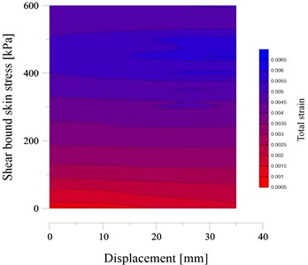
Fig. 10The kriging estimation of displacement considering pull-out shear stress and grouting pressure
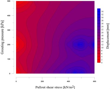
Displacement and bond strength has been directly estimated by using the Fig. 10 that generated by using the Kriging method. The grouting pressure effect on the shear strength has been illustrated in this figure. It is shown that in case of high bound strength by increasing the grouting pressure, the Disp would be reduced. While in case of weakly bound strength, the grouting pressure effects can be negligible.
3.1. Results of Regression estimation
Due to principal assumptions, to develop new relationships for finding the nailing system displacement, four different linear regressions had been conducted. The coefficient determination and standard error for the estimation have been reported in Table 7. The result of the general model shows that it has the fully linear behaviour by achieving the square 0.997. While the achieved results of Disp in the case of model 1 also show that considering grouting pressure effects the square coefficient would be reduced up to 9 percent. It means that the grouting pressure might become a nonlinear behaviour compares with gravity pressure. However, the outcome square in both cases of model 2 and 3 are lower than general model while both of them are reported extremely similar.
Table 7Result of coefficient determination and error coefficient in developed models
Model | Square | Adjusted square | Std. error of the estimate |
General | 0.997 | 0.997 | 0.4704 |
1 | 0.911 | 0.907 | 2.65656 |
2 | 0.895 | 0.891 | 2.87263 |
3 | 0.910 | 0.907 | 2.66062 |
To develop relationship related to general model is driven as Eq. (1). It has 11 different parameters as inputs. While the measuring of someone of inputs such as total strain is not so easy. Hence this equation would be so used fully in case of verification:
To consider the effects of pressured grouting the relationship that related to model 2 is generated as Eq. (2). Hence it is able to consider pressure effect and removed the strain parameters. This equation is probably useful and practical while it has around 10 different input that they would become complicated to use in a relationship:
Due to the aim of current work and to use minimum input parameters for developing new practical relationships the following equations have been generated. Eq. (3) is able to estimate Disp without considering the grouting pressure and Eq. (4) is capable to estimate Disp considering grouting pressure as well:
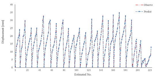
The extracted results of the general model and experimental pull-out tests have been shown in Fig. 11. The reasonable result has been observed due to use this verification. Hence negligible overestimation results would be occurred by using the Eq. (1).
Fig. 11Comparison results of new developed relation for general model and experimental work
Results for estimation capability for Eq. (2) that has used to consider grouting effect is also illustrated in Fig. 12. It is observed that the effect of grouting pressure in the collaboration for estimating the Disp would have decreases role in a comparison with gravity grouting cases. While considering the pressure effect may decrease the normal linear behaviour for Disp and it may be changed to nonlinear behaviour. Hence, the G.P effects can increase the estimation error. Results showed that in case of higher pressure grouting the error for estimation would be increased while in case of lower pressure it has a reasonable estimation. Therefore, it is recommended to use the Eq. (2) for estimating just in grouting pressure values lower than 500 kPa.
Fig. 12Comparison results of new developed relation for model 1 and experimental work
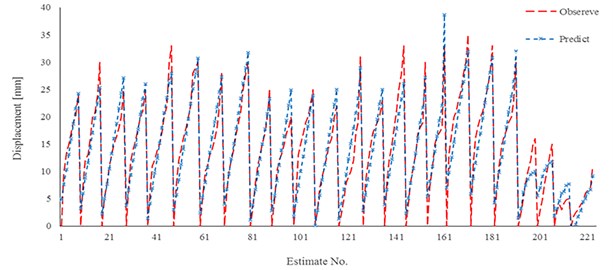
Fig. 13Results of linear regression for model 2 and experimental work
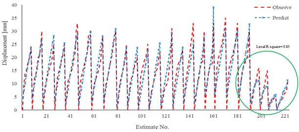
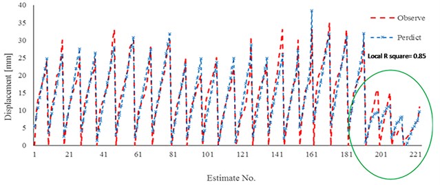
Results of two practical developed relationships (Eq. (3) and Eq. (4) are also shown in Fig. 13 and Fig. 14. With an emphasis on gravity pressure, it is observed that the estimated values by using the Eq. (3) a good estimation for displacement in a compare with extracted results of experimental work would be illustrated. Figures show that in the last part of each relation estimation the maximum error to estimate the displacement would occur. The local result of coefficient determination is near 0.85. The main reason of this weakly estimation is outcome regarding the difference in injection pressure and nail elastic modulus. Hence it would have resulted that mentioned relationships have an excellent estimation in case of grouting pressure lower than 500 kPa and normal elastic modulus for bars.
Fig. 14Results of linear regression for model 3 and experimental work
3.2. Neural network prediction
A multi-layer neural network is generated to verify the results of model 2 and 3. A one hidden layer neural network by using the hyperbolic tangent for activation has been considered to estimate the Disp. In addition, 8 different input factors for two cases of neural network have been used and have reported in Table 8. Furthermore, 221 different data are used as neural network’s input parameters. 70 percent of input data have been used for training step and others used for test step in neural network processing. The identity function is also used for the output activation function. Finally, the Sum of Squares has been chosen for error investigating in the network structure. The generated structure of the neural network in the current study has been shown in Table 8.
Table 8Structure of input, hidden and output layer of neural network
Input layer | Factors | M.C | |
Ø | |||
P.S.S | |||
O.B | |||
G.P* | |||
Hidden layer(s) | Number of units | 62 | |
Number of hidden layers | 1 | ||
Number of units in hidden layer 1a | 2 | ||
Activation function | Hyperbolic tangent | ||
Output layer | Dependent variables | 1 | Displacement |
Number of units | 1 | ||
Rescaling method for scale dependents | Standardized | ||
Activation function | Identity | ||
Error function | Sum of Squares | ||
* G.P is used just in Neural network model 2 | |||
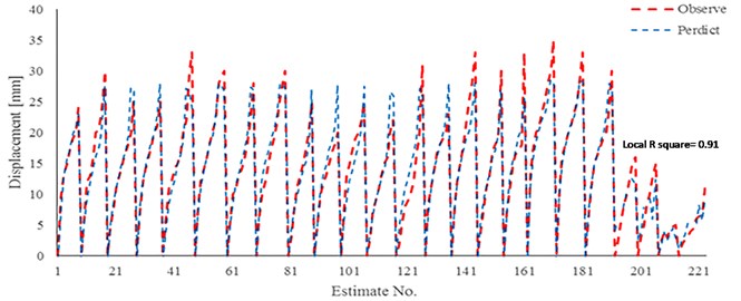
The results of neural network predicting for both generated neural networks are reported in Fig. 15 and Fig. 16. The coefficient determination for the first neural network is found 0.95. The mentioned coefficient for the second model of neural network (G.P effect) is also reported 0.91. It is observed that the neural network has a good estimation in case of high-pressure grouting and high range of nail elastic modulus.
Fig. 15Comparison results of neural network (Model 1) and experimental work to estimate of displacement
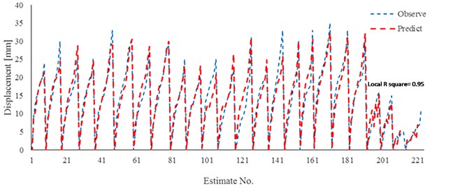
Fig. 16Comparison results of neural network (Model 2) and experimental work to estimate of displacement
Results for each conducted analysis in this work are shown in Fig. 17. It has been observed that the maximum error occurred in case of linear regressions (L.R) models that have estimated around 10 percent. However, in case of high-pressure the neural network has done better estimation in a compare with the L.R. Due to all of the achieved results it would be recommended to use the linear regressions in case of gravity pressure or pressure grouting not more than 300 kPa and normal stiffness steel. Moreover, in case of highly pressured grouting and stiff nail bar the generated neural network in current work would be able to excellent estimate the Disp.
Fig. 17Complete comparison for all analysis during current study
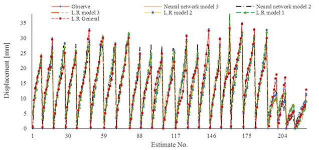
To show comparison results separately, the achieved results of developed relationships, neural network experimental pull-out test have been plotted in Figs. 18 to 21. The nonlinear estimation of neural network has been illustrated in mentioned figures.
Fig. 18Results of displacement estimation in site of Gyeonggi: a) displacement estimation in case of high grouting pressure [500 kPa]; b) displacement estimation in case of gravity pressure grouting
![Results of displacement estimation in site of Gyeonggi: a) displacement estimation in case of high grouting pressure [500 kPa]; b) displacement estimation in case of gravity pressure grouting](https://static-01.extrica.com/articles/19597/19597-img22.jpg)
a)
![Results of displacement estimation in site of Gyeonggi: a) displacement estimation in case of high grouting pressure [500 kPa]; b) displacement estimation in case of gravity pressure grouting](https://static-01.extrica.com/articles/19597/19597-img23.jpg)
b)
Fig. 19Results of displacement estimation in site of Shahrak gharb: a) displacement estimation in case of gravity pressure grouting and 4 meters of O.B; b): displacement estimation in case of high grouting pressure [200 kPa] and 4 meter O.B.
![Results of displacement estimation in site of Shahrak gharb: a) displacement estimation in case of gravity pressure grouting and 4 meters of O.B; b): displacement estimation in case of high grouting pressure [200 kPa] and 4 meter O.B.](https://static-01.extrica.com/articles/19597/19597-img24.jpg)
a)
![Results of displacement estimation in site of Shahrak gharb: a) displacement estimation in case of gravity pressure grouting and 4 meters of O.B; b): displacement estimation in case of high grouting pressure [200 kPa] and 4 meter O.B.](https://static-01.extrica.com/articles/19597/19597-img25.jpg)
b)
Fig. 20Results of displacement estimation in site of Shahrak gharb: a) displacement estimation in case of gravity pressure grouting and 8 meters of O.B; b) displacement estimation in case of high grouting pressure [200 kPa] and 8 meter O.B.
![Results of displacement estimation in site of Shahrak gharb: a) displacement estimation in case of gravity pressure grouting and 8 meters of O.B; b) displacement estimation in case of high grouting pressure [200 kPa] and 8 meter O.B.](https://static-01.extrica.com/articles/19597/19597-img26.jpg)
a)
![Results of displacement estimation in site of Shahrak gharb: a) displacement estimation in case of gravity pressure grouting and 8 meters of O.B; b) displacement estimation in case of high grouting pressure [200 kPa] and 8 meter O.B.](https://static-01.extrica.com/articles/19597/19597-img27.jpg)
b)
Fig. 21Results of displacement estimation in site of Artesh: a) displacement estimation in case of high grouting pressure [200 kPa] and 8 meters of O.B; b) displacement estimation in case of gravity pressure grouting and 8 meter O.B.
![Results of displacement estimation in site of Artesh: a) displacement estimation in case of high grouting pressure [200 kPa] and 8 meters of O.B; b) displacement estimation in case of gravity pressure grouting and 8 meter O.B.](https://static-01.extrica.com/articles/19597/19597-img28.jpg)
a)
![Results of displacement estimation in site of Artesh: a) displacement estimation in case of high grouting pressure [200 kPa] and 8 meters of O.B; b) displacement estimation in case of gravity pressure grouting and 8 meter O.B.](https://static-01.extrica.com/articles/19597/19597-img29.jpg)
b)
The sensitivity analysis for the rate of important parameters has been performed. Related results are also shown in Fig. 22. It is observed that in case of pressure grouting the degree of importance of P.S.S will decrease compared with gravity pressure cases. While in case of pressure grouting the O.B and hole diameter have considerable effects compare with the results of gravity grouting. Furthermore, the result shows that in non-pressure grouting, the soil mechanical properties have a significant effect to decrease the displacement. However, in case of pressured grouting, the effective parameters have been changed. Parameters O.B, D, and have an integral role to estimate the nailing system displacement compare with their role in gravity grouting.
Fig. 22The values of importance factor in case of a) pressure grouting and b) gravity grouting
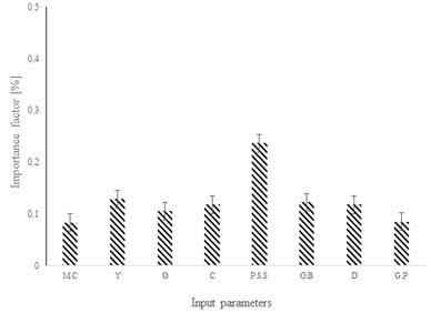
a)
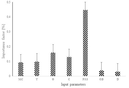
b)
4. Conclusions
The number of the experimental pull-out test has been done and their results are used as input data to develop the new relationship for estimating the displacement of a nailing system. The standard procedures of the pull-out test have been performed in five different sites in Tehran, Iran. Moreover, results of a previous experimental work are chosen as additional data. Furthermore, new relationships to consider the grouting pressure effect on displacement has been considered. New relationships for both cases of gravity and pressured grouting has been developed. The following Conclusions are extracted from current research:
1) The two times increasing in G.P can increase the pull-out shear stress maximum to three times. It means the grouting pressure maximum to 600 kPa would be increase the bond strength to three time greater compare with gravity grouting conditions.
2) Results of developed relationships showed that the general relationship is able to estimate displacement with lowest error and determination coefficient 0.99. Hence it is so useful for verification. Furthermore, results of other models have had determination coefficient among 0.89 to 0.91. The result of this relation showed that dependency of bound skin fraction to other significant gravity grouting factors could be linear. However, in case of pressure grouting, the dependency is changed to nonlinear.
3) Achieved results showed the linear regressions have good estimating for displacement considering gravity and pressure grouting not more than 300 kPa. In case of higher pressure grouting and high stiffness steel bar, the recommends neural network would be more capable of better estimation compare with linear regression.
4) Maximum importance factor related to input considered in both case of gravity and pressured grouting is reported by P.S.S. achieved result show that the soil mechanical property is the major factor which has significant effect on nailing system displacement. Parameters and moisture content have secondary powerful effects upon nailing system displacement. In case of pressured grouting the pattern of s importance factor for parameters will be changed. The effects of and O.B will be increased until 3 times.
References
-
Elias V., Juran I. Soil Nailing for Stabilization of Highway Slopes and Excavations. Federal Highway Administration. Washington, DC, USA, Publication FHWA-RD-89-198, 1991.
-
Lazarte C. A., Elias V., Espinoza R. D., Sabatini P. J. Soil Nail Walls. Geotechnical Engineering Circular No. 7. Federal Highway Administration, Washington, DC, USA, Publication FHWA-IF-03-017, 2013.
-
Schlosser F. Behaviour and design of soil nailing. Proceeding on Recent Developments in Ground Improvement Techniques, Bangkok, Thailand, Balasubramaniam AS, Chandra S, 1982.
-
Shahraki Ghadidmi A., Ghanbari A., Sabermahani M., Yazdani M. Effect of soil type on nail pull-out resistance. Ground Improvement, Vol. 170, Issue 2, 2017, p. 81-88.
-
Yin J. H., Zhou W. H. Influence of grouting pressure and overburden stress on the interface resistance of a soil nail. Journal of Geotechnical and Geoenvironmental Engineering, Vol. 135, Issue 9, 2009, p. 1198-1208.
-
Chu L. M., Yin J. H. Comparison of interface shear strength of soil nails measured by direct shear box tests and pull-out tests. Journal of Geotechnical and Geoenvironmental Engineering, Vol. 131, Issue 9, 2005, p. 1097-1107.
-
ACI 318-2005: Building Code Requirements for Structural Concrete and Commentary. ACI, Farmington Hills, Michigan, 1995.
-
Zhou W. H., Yin J. H., Zhu H. H., Hong C. Y. Study on the effects of grouting pressure and overburden pressure on the pullout resistance of soil nails. Proceedings of the 60th Canadian Geotechnical Conference and 8th joint CGS/IAH-CNC Groundwater Conference, Ottawa, ON, Canada, 2008, p. 985-990.
-
Zhou W. H., Yin J. H., Zhu H. H., Hong C. Y. Effects of overburden stress and grouting pressure on soil nail pull-out resistance. Proceedings of the 17th Southeast Asian Geotechnical Conference, Taipei, Taiwan, 2010, p. 248-251.
-
Yin J., Hua C., Zhou W. Simplified analytical method for calculating the maximum shear stress of nail-soil interface. International Journal of Geomechanics, Vol. 12, Issue 3, 2012, p. 309-317.
-
Kim Y., Lee S., Jeong S., Kim J. The effect of pressure-grouted soil nails on the stability of weathered soil slopes. Computers and Geotechnics, Vol. 49, 2013, p. 253-263.
-
ASTM D422-63: Standard Test Method for Particle-Size Analysis. ASTM International, West Conshohocken, PA, USA, 1992.
-
ASTM D3080/D3080M-11: Standard Test Method for Direct Shear Test of Soils Under Consolidated Drained Conditions. ASTM International, West Conshohocken, PA, 2011.
-
ASTM D2216-10: Standard Test Methods for Laboratory Determination of Water (Moisture) Content of Soil and Rock by Mass. ASTM International, West Conshohocken, PA, 2010, www.astm.org.
-
ASTM D4564-08e1: Standard Test Method for Density and Unit Weight of Soil in Place by the Sleeve Method (Withdrawn 2013). ASTM International, West Conshohocken, PA, 2008, www.astm.org.
-
ASTM D1195/D1195M-09: Standard Test Method for Repetitive Static Plate Load Tests of Soils and Flexible Pavement Components, for Use in Evaluation and Design of Airport and Highway Pavements. ASTM International, West Conshohocken, PA, 2015, www.astm.org.
About this article

The authors wish to appreciate the institute of geotechnical engineering, University of Bodenkultur, Vienna, Austria, for their generous supports to complete this work.
