Abstract
Energy is released during explosions, and this creates shock waves. The dynamic pressure generated from an explosion is transmitted through soil in the form of compression waves. In military engineering and industrial safety protection, soil, a blast-resistant material, is used to achieve blast resistance. This study used the blast pressure and ground acceleration measured in an experimental explosion to verify the results of finite element numerical analysis. A fluid–solid interaction numerical analysis method was employed to simulate a trinitrotoluene explosion on the ground. Through analysis of the dynamic characteristics of soil after an explosion, the relationship between the dynamic stress wave formed by the explosion and the plastic deformation of the soil was studied. The results may provide a reference for the design of blast-resistant protective soil layers.
Highlights
- Analyze the dynamic time and space varying reactions of soil
- Analyze the high-intensity shock wave and transmitted through soil
- Analyze the dynamic mechanic characteristics and deformation effect on the soil
- Fluid-solid interaction method is used to calculate dynamic pressure
- Research results may serve as a reference for blast disaster control
1. Introduction
Geotechnical engineering is the basis for the construction of various facilities. Engineering project analyses mainly investigate the stability of a material and its deformation. The stress impact from an explosion affects the stability of a material. The dynamic reaction of a structure is related to its velocity, acceleration, and displacement. Blast-resistant engineering for a structure is designed for safety protection. Burster layers can be used to prevent blast damage to underground structures. A soil protection layer can stop energy transmission from shock waves, thereby controlling the danger of and damage caused by explosions. Therefore, the design of a blast-resistant burster layer must prevent penetration and reduce shock and pressure. The researcher in this study examined the dynamic mechanical behavior and deformation characteristics of blast-resistant burster layers. On the basis of the theories of explosive mechanics and soil dynamics, this study was conducted using explosion experiments and numerical simulation analysis. The dynamic characteristics of a shock wave transmitted through the medium of soil were analyzed. Furthermore, the stress, strain, deformation, and displacement of soil subject to stress were analyzed to evaluate the engineering measures.
An explosion is a phenomenon during which energy is quickly released. The air pressure rapidly increases, forming dynamic pressure. During the process of energy transformation and transmission, a shock wave is formed. The high-temperature, high-pressure gas is called a blast wave. Part of the energy from blast pressure is transmitted to the ground surface. This forms shock waves that generate shock pressure on the objects they contact, triggering vibrations in ground particles; this is called an explosion [1]. The stress wave from an explosion affects the stability of a material. When the ground explodes, it causes compression waves and elastic seismic waves in the soil. Compression waves are the key parameter affecting vibration [2]. The dynamic shock wave generated from an explosion is transmitted outward through a medium. The processes of energy transformation and transmission trigger an earthquake. The media that transmit stress waves are diverse and uncertain [3, 4]. Soil is composed of solids, liquids, and gases, all of which are heterogeneous and anisotropic compressible porous materials. During the early phase of an explosion, the blast wave is transmitted in the form of a shock wave. Later, it is transformed into an elastic seismic wave, triggering vibration in ground particles. The soil compression wave generated when the ground explodes is eventually transformed into an elastic seismic wave [5, 6]. The shock wave energy is high at the center of an explosion, as is the strength of the corresponding soil compression wave, which is the key factor causing ground vibration. During the explosion process, energy is released instantly and shock waves are generated. Overstress is transmitted in the soil, and the strain and displacement of particles are influenced by the shock waves [2, 7]. The shock waves compress the soil, resulting in a concentration of stress that influences the soil’s stability.
Soil is an anisotropic and heteropic material, and its strength provides resistance to destruction. The key factor of material failure is the critical state reached by the combination of normal stress and strain. When shear strain exceeds the ultimate strength of the material, shear strength disappears, and the soil loses its equilibrium [8]. When the strain reaches the ultimate strength of the material, instability induces surface cracks and subsidence, leading to geological hazards such as tilting or subsidence of structures on the ground [9, 10].
Shock waves create overstress that is transmitted through soil, resulting in an irreversible stress–strain relationship. The loading and unloading of soil are influenced by shock waves. Blast effect analysis is based on the theories of mass, energy, and conservation of momentum during energy transformation and transmission [1]. The scale of ground vibration is affected by the shock wave energy. Results of a magazine explosion analysis showed that free-field blast pressure was approximately one-third of the ground blast pressure, the relative errors of the experimental data and numerical analysis results were within 15 %, and the relative error of the impulse was approximately 9 % [11]. Protection from the effects of blast vibrations is divided into shock resistance and shock isolation. When analyzing the physical quantity of an explosion hazard, the evaluation parameters are mainly the displacement, velocity, acceleration, stress, and strain of the material. The vibration speed of a particle in the direction vertical to the ground is the main reference in engineering designs [12, 13]. The damage from near-ground and ground explosions is analyzed using shock wave energy and ground vibration strength [14]. In addition, data from nuclear explosions can be used to explain the reaction process of explosions in midair or on the ground, leading to stress and deformation in soil. In a ground explosion, the yield strength of soil is used to analyze the impact of the blast wave. After analyzing the transmission characteristics of blast waves in soil, this study analyzed the factors influencing the strength of vibration and its impact on soil structure. A key indicator for the evaluation of safety measures required for a protected object is the acceleration and displacement of a particle triggered by the explosion [12]. Peak ground acceleration is a physical quantity used to measure the strength of a vibration [15, 16].
Explosion analysis is highly nonlinear. Research on shock wave effects has included dynamic analysis of geometric, material, and contact nonlinearity. Explosion experiments are somewhat hazardous, and computer-aided engineering analysis eliminates dangers during the experimental process. In the analysis of a safety system, experimental data are used to verify numerical analysis results. To control the destructive effects of an explosion, this study investigated the dynamic reaction of soil under the impact of explosive stress. Through analysis of the stress and strain behaviors of soil subject to a blast, this study investigated soil’s displacement and deformation processes. On the basis of the material’s engineering characteristics, this study employed numerical analysis and explosive experimental methods. The results may serve as a reference for designing protective soil layers and blast-resistant engineering measures.
2. Materials and methods
This study used the theory of mechanics. Experimental results were employed to verify the numerical analysis model, specifically the dynamic characteristics of soil subject to shock wave impacts. The finite element method (FEM) is a numerical analysis method widely applied in various research fields. The FEM, coupled with a numerical model and corresponding numerical algorithm, can be employed to analyze a material’s stress field, displacement field, and mechanics characteristics. The loading time of an explosion effect is short, and the vibration frequency is high. Explosions can be represented as an instant dynamic analysis problem. In addition, the dynamic mechanical characteristics of an explosion correspond to complex geometric shapes, the variability of material properties, and the nonlinear behavior of the material. This study analyzed the dynamic time- and space-varying reactions.
For numerical analysis, this study employed the dynamic analysis software package LS-DYNA, which has both explicit and implicit solution functions. Hydrodynamic software uses hydrodynamics to calculate the dynamic behavior of the gas generated in an explosion, fluid-solid interactions, and the instant dynamic problems of geometric, material, and contact nonlinearity. Its advantages are that it enables analysis of the nonlinearity of three-dimensional (3D) space as well as of large deformation, and it is suitable for the calculation of dynamic nonlinearity problems involved in blasts and impacts [17-19].
2.1. Experimental equipment and approach
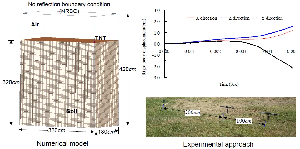
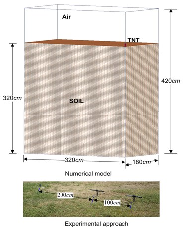
This study used the shock wave pressure produced by and ground acceleration induced by an explosion to verify the accuracy of the numerical analysis model. The goal of the explosion experiment was to measure the free-field air explosion pressure that was in contact with the explosion and the ground acceleration to verify the numerical analysis model. In the onsite experiment, this study used 113.389 g (0.25 lb) of trinitrotoluene (TNT) in a cuboid form standing vertically and making contact with the ground. Soil was sampled from the explosion field. Its water content was 10.27 %, and the soil density was 1.78 g/cm3. According to the Unified Soil Classification System, the soil was classified as SC, whereas according to engineering classifications, it was sand with the characteristics of clay. The experimental analysis of direct shear revealed that the shear force parameter cohesion () and angle of friction () were 0.95 kg/cm2 and 36°, respectively.
Fig. 1 presents the overall configuration of the experimental explosion site and measurement device. To measure the near-ground free-field shock wave pressure during the experiment, blast meters were placed 200 and 300 cm from the explosion center.
Fig. 1Overall configuration of the blast pressure and ground acceleration experimental field and signal acquisition system
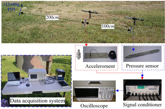
The height of the sensor was the same as that of the TNT, approximately 9 cm from the ground. The pressure sensor was a blast pressure pencil probe (model 137A23; PCB Piezotronics, NY, USA). This blast meter can measure the blast pressure in a free field. It has a pen-like metal stick shape, and the sensor is located approximately one-third of the distance from the front of the metal stick. The maximum measurement of blast pressure was 6,895 kPa. To measure the ground acceleration triggered by the explosion, a vertical axial accelerometer was placed 200 cm above the explosion center. The transmission of signals generated by the blast meter and accelerometer was performed by connecting these devices to an oscilloscope through a signal conditioner. Other equipment included power supply and data acquisition systems. The transmission of signals quantity examines blast pressure and ground acceleration via the oscilloscope through a signal conditioner at the same time.
2.2. Establishing the finite element model
According to the research question, analysis type, and algorithm, this study used the solid elements of an eight-node hexahedron together with the multimaterial arbitrary Lagrangian Eulerian (MMALE) algorithm to establish a 3D spatial solid structure model for describing fluid-solid interaction. Each element in the model is defined as having eight nodes. The range of values for the node locations is represented by ±1. Each node has nine degrees of freedom. Their volumes under compressive stress or large deformation are larger than 0, which is suitable for analyzing explicit dynamic temporal and spatial problems [20].
The Lagrangian algorithm is based on material coordination. By contrast, the Eulerian algorithm is based on spatial coordination. In the MMALE algorithm, the Lagrangian algorithm is adopted to analyze solid materials, whereas the Eulerian algorithm is employed for fluid materials. This algorithm overcomes the problem of computation suspension in numerical analysis due to large mesh deformation. Furthermore, it controls and tracks the movement behavior of the boundary structure and is thus suitable for the instant dynamic analysis of fluid–solid interaction. Moreover, it satisfactorily analyzes large displacement and deformation from explosions, blasts, and high-speed collisions. To analyze the dynamic reaction of fluid–solid interaction to shock waves in the soil, the Lagrangian algorithm was used to analyze the solid element, whereas the Eulerian algorithm was used to analyze the liquid element [21].
Fig. 2 displays the one-quarter initial symmetrical model used in numerical simulation analysis for ground contact explosions. The numerical analysis model was established with a unit system in g, cm, μ-second, MPa. For the instant dynamic analysis of fluid–solid interaction, the Eulerian algorithm was used to analyze the elements of TNT and air, and the Lagrangian algorithm was used to analyze soil. In this study, 3D SOLID164 elements were used to construct the numerical analysis model. The meshes of the fluid and the solid were independent, and the density of the solid mesh was twice that of the fluid. The interaction between the fluid mesh and solid mesh was constructed through overlapping [22]. After the CONSTRAINED_LAGRANGE_IN_SOLID program setting was used, the numerical analysis model of the MMALE algorithm was established.
Fig. 2One-quarter initial symmetrical numerical simulation model of the explosion on the ground
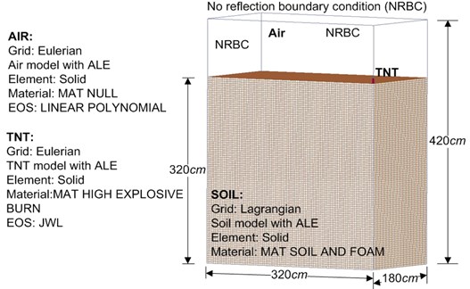
The explosion experimental condition was set to no reflex boundary. Because of the symmetricity of the model, only one-quarter of the model was used for analysis. The numerical model boundary condition was set to no reflex boundary for all surfaces apart from the symmetrical level. Air was defined as the ideal gas, and the air material model was 320 × 180 × 420 cm3. The rectangular TNT (3.28 × 3.28 × 9.3 cm3) weighed 113.389 g (0.25 lb) and had a density of 1.63 g/cm3. It was placed at the center of the model in contact with the ground. The point of explosion was at the center. The soil model measured 320 × 180 × 320 cm3. The application of finite element analysis requires consideration of the complexity of an analysis model and of the mesh density. A TNT free-field explosion simulation was analyzed for mesh density convergence under an explosive load. The analysis results revealed the optimal mesh density to be 0.5 times that of the side length of the TNT; the time-step control parameter was set to 0.3 [18]. Per the conversion analysis of the numerical model, the smallest width of the TNT was adopted as a reference for the mesh size, and the Eulerian mesh was set to 0.5 times the smallest width of the TNT. The minimum mesh scales of the rectangular TNT (3.28 × 3.28 × 9.3 cm3), air, and soil were 1.64, 1.64, and 3.28 cm, respectively.
2.3. Material parameters and equation of state
The material constitutive law is expressed through the stress-strain relationship. When a material undergoes large displacement or deformation, the corresponding equation of state is required for analysis to reflect the actual dynamic characteristics of the material. To analyze an explosion, as well as the basic parameters of a material, the corresponding equation of state is required. Table 1 presents the material parameters of air, TNT, and soil. The air model used the software package’s MAT NULL material mode corresponding to the EOS LINEAR POLYNOMIAL equation of state to analyze the free-field shock wave characteristics. The equation is shown in Eq. (1). The parameters of the air model include mass density, pressure cutoff, dynamic viscosity coefficient, initial internal energy, Young’s modulus, and Poisson’s ratio [3, 20]:
with , where is the initial energy of a unit volume; is the dynamic viscosity parameter; is the relative volume; and - are constants.
For the TNT model, the Jones-Wilkins-Lee equation of state [Eq. (2)] was adopted from the dynamite manual of the Lawrence Livermore National Laboratory in the United States; this equation corresponds to the MAT HIGH EXPLOSIVE BURN material model in the LS-DYNA equation. It is used to study high speeds, temperatures, and pressures as well as the rapid release of energy during large explosions. For the analysis parameters, this study referred to the LS-DYNA manual and the Lawrence Livermore National Laboratory dynamite manual. The TNT material parameters were mass density, detonation velocity, Chapman-Jouguet pressure, beta burn flag, bulk modulus, shear modulus, and yield stress [17, 23]:
where is the pressure; is the relative volume; is the initial internal energy per unit reference specific volume; and , , , , and are constants representing characteristics of the explosive.
The soil composition model, stress and strain analysis model, and material yielding principle were employed to analyze the characteristics of porous materials and dynamic reactions after a blast. The Krieg yielding principle is based on isotropic plastic theory, which can be used to analyze the crushing or compacting behaviors of porous materials under pressure. The stress-strain relationship in a material before it yields can be analyzed on the basis of linear plasticity. After plastic deformation, the relationship follows the plastic mechanics principle. Damage to a material is controlled by shear force. To analyze the dynamic phenomenon of porous materials, this study divided the behavior of such materials after they yielded into hydrostatic pressure and shear force [24].
Table 1Material parameters and equation of state
Element | Material and equation of state parameters (unit: g, cm, μ-second, MPa) | |||||
Air | MAT_NULL | |||||
Density, | Pressure cutoff, | Young’s modulus, | Poisson’s ratio, | Initial internal energy, | ||
0.00129 | 0.0 | 0.0 | 0.0 |  | ||
EOS_LINEAR_POLYNOMIAL | ||||||
Constants | ||||||
, , , | Initial relative volume, | |||||
 | 0.0 | 0.4 | 0.4 | 1.0 | ||
TNT | MAT_HIGH_EXPLOSIVE_BURN | |||||
Density, | Detonation velocity, | Chapman-Jouget pressure, | Initial internal energy, | |||
1.63 | 0.693 | 0.21 | 0.07 | |||
EOS_JWL | ||||||
Constants representing characteristics of the explosive | OMEGA, | Initial relative volume, | ||||
3.712 | 0.03231 | 4.15 | 0.95 | 0.3 | 1.0 | |
Soil | MAT_SOIL_AND_FOAM | |||||
Density, | Elastic modulus, | Shear modulus, | Bulk modulus, | |||
1.78 | 43.75 MPa | 14.68 MPa | 729 MPa | |||
Shear-yield surface parameters | ||||||
9.025×10⁻¹², 1.38×10⁻¹¹, 5.28×10⁻¹² | ||||||
In LS-DYNA code, the shear failure principle of the soil and rock model reflects the relationship between the average stress and failure strength. The yielding function is shown in Eq. (3), the second invariant of stress deviation is shown in Eq. (4), and the axial yield stress is shown in Eq. (5). The shear yield surface parameters are , , and . A soil composition model must simulate the consolidation or compaction characteristics of porous materials. Material characteristics were used to analyze the dynamic reaction of soil after a blast force. A material model using MAT_SOIL_AND_FOAM was used to calculate the shear failure of the porous material by using the average stress and failure strength [20].
The basis of material failure was defined with the element erosion criterion MAT_ADD_EROSION. Soil is a low-resistance material. According to the relationship between material stress and strain, this study defined the maximum shear strain () and failure shear strain () as elemental erosion failure conditions. As the conditions of the erosion criterion were established, and the material failure criterion was satisfied, the element was deleted from the calculation model [20]:
where is the yield function; is the second invariant of deviatoric stress; is the pressure; - are the shear yield surface parameters; and is the yield stress.
3. Results and discussion
3.1. Numerical analysis model for verifying the explosion experiments
The main objective of this study was to analyze the dynamic reaction and deformation of soil subject to blast force. An explosion generates shock waves. We therefore employed shock wave pressure and ground acceleration to analyze the characteristics of shock waves. In the ground explosion experiment, the free-field near-ground blast pressure and ground acceleration were measured to verify the numerical analysis model. The relative error (%) of the numerical analysis and experimental results was equal to (numerical analysis value − experimental measurement value) / experimental measurement value × 100 %.
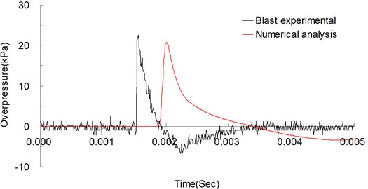
To verify the blast effect, the maximum ground acceleration in the vertical direction 200 cm from the explosion center was used. Fig. 3 shows the vertical acceleration curves from the explosion experiment measured at 200 cm from the explosion center over time and those from the numerical analysis. The maximum values from the experiment and numerical analysis were 6.806 gal (m/s2) and 6.216 gal (m/s2), respectively; the relative error was −8.679 %. The near-ground blast pressure shock waves 200 and 300 cm from the explosion center were used to analyze the shock wave energy. Figs. 4 and 5 respectively show the blast pressure curves for the points 200 and 300 cm from the explosion center. At 200 cm from the explosion center, the experimental and numerical analysis values for the near-ground blast pressure were 50.297 and 45.826 kPa, respectively; the relative error was −8.890 %. At 300 cm from the explosion center, the experimental and numerical analysis values for the near-ground blast pressure were 22.534 and 20.718 kPa, respectively; the relative error was −8.059 %. These results agree with those of another relevant study [11].
Fig. 3Acceleration curves of explosion experiment and numerical analysis over time, measured perpendicular from the ground 200 cm above the explosive source
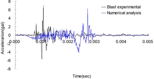
Figs. 3, 4, and 5 depict the duration curve and relative error for numerical analysis and experimental results. The reception of surface acceleration and explosion pressure signals in the onsite experiment was triggered by the instrument, and the numerical analysis results presented the duration curve of the particle. Due to the complexity of the explosive environment, material parameters and equations of state of the numerical analysis cannot fully reflect the experimental conditions and complex environmental factors. Although the numerical analysis and experimental results were not consistently accurate, the analyzed duration curve displayed a consistent trend, and the overall analysis results were in agreement with the facts.
The research results demonstrated that a fluid’s dynamic behavior and its interaction with solids could be analyzed using 3D SOLID164 elements together with numerical fluid-solid interaction models and the MMALE algorithm, thereby solving the dynamic analysis problems of material, geometric, and contact nonlinearity. The results indicated that the 3D spatial solid structure model and analysis parameters were reasonable. The results were then used to analyze the dynamic effects of an explosion on soil.
Fig. 4Blast pressure curves of explosion experiment and numerical analysis over time, measured 200 cm from the explosive source
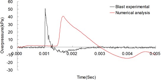
Fig. 5Blast pressure curves of explosion experiment and numerical analysis over time, measured 300 cm from the explosive source
3.2. Shock and seismic waves
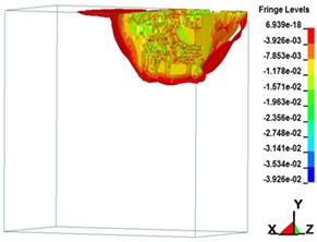
A shock wave transmits energy, in the form of pressure, to the ground directly or through the air. When the ground explodes, the blast impacts the air and causes a shock wave, creating air-induced ground motion and triggering directly transmitted ground shocks. Fig. 6 illustrates the transmission of ground explosion shock waves over time. Fig. 6(a-h) depict the free-field shock wave rapidly moving spherically outwards under pressure. In a few milliseconds, the energy attenuated. During the process of pressure transmission, if no reflection wave is encountered, a dynamic pressure similar to wind pressure is formed in the area behind the blast. Following an explosion, the region of influence from the center outward can be divided into the compression zone, fracture zone, and vibration zone. Influenced by the shock wave, high-intensity stress impact is generated. From the explosion’s center, shock, compression, and seismic waves emanate. A seismic wave triggered by an explosion is triggered mainly by the air impact. When the surface of the ground explodes, a compression wave and elastic seismic wave in the soil can simultaneously be measured. The compression wave has abundant energy, which triggers vibration in particles on the ground surface. Soil is a material with low tensile strength. Under the influence of shock waves, particle vibrations accelerate, thereby increasing the shear force in the soil, resulting in particle strain and displacement.
Fig. 6Free-zone shock wave transmission over time in the ground surface explosion
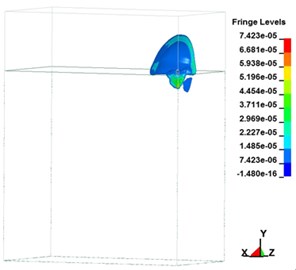
a) 249.95 μs
b) 499.44 μs
c)999.39 μs
d)1,508.10 μs
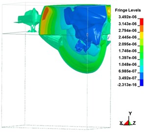
e) 2,009.60 μs
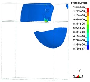
f)2,499.80 μs
g)2,999.80 μs
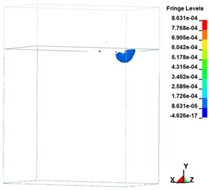
h)5,000.00 μs
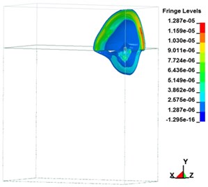
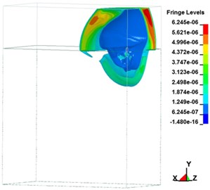
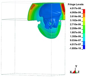
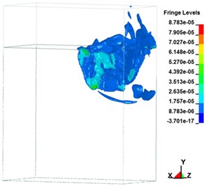
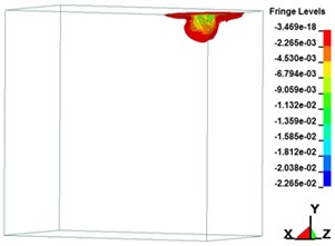
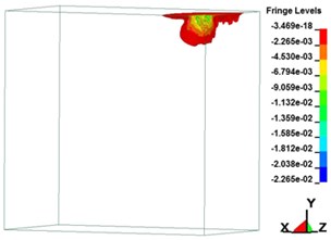
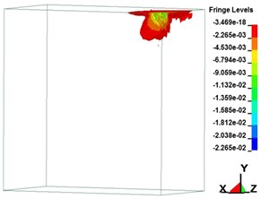
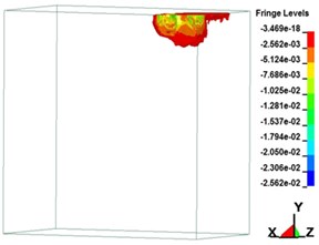
Fig. 7Plastic strain on soil over time
a) 249.95 μs
b) 499.44 μs
c) 999.39 μs
d) 1,508.10 μs
e) 2,009.60 μs
f) 2,499.80 μs
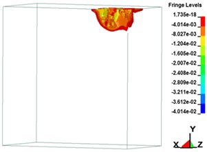
g) 2,999.80 μs
i) Experimental plan and numerical model
h) 5,000.00 μs
3.3. Material failure and deformations in surrounding soil
Fig. 7 illustrates the soil plastic strain over time. The maximum strain values in the , , and directions were 0.013, 0.0068, and 0.012, respectively. In dynamic reaction analysis, the pressure, stress, and strain on a material are evaluated. The large strain generated by an explosion shock wave influences the internal stress of the soil, leading to soil strain. The blast influences the stress condition of the soil, resulting in particle displacement and deformation. When the stress on the soil exceeds its yield strength, its internal structural stability is affected. Through analysis of material deformation, plastic strain over time, displacement, and increase in shear strain, the stability state of soil was determined. The results revealed that after the yield strength of the soil was exceeded due to the blast, plastic deformation occurred in the material. The plastic strain analysis process revealed that the failure in the soil caused by the blast loading effect began in the area of plastic deformation. Uneven stress distribution reduced the shear strength of the material. Moreover, blast loading triggered a compression wave in the soil, leading to increased strain in the material. When this strain exceeded the yield strength of the soil, displacement occurred, and when this displacement reached a critical level, the soil deformed and broke. Therefore, the blast affected the stress state of the soil, influencing its strength and stability.
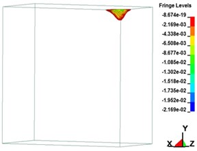
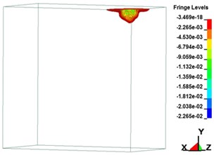
Fig. 8 indicates the crater effects caused by ground contact explosions of 113.389 g (0.25 lb) of TNT. Soil can withstand pressure more easily than it can tension and shear forces. When researchers analyze the dynamic reaction of soil against ground explosions, they must consider that a ground explosion forms a hypocenter that transmits energy outward through the soil. The shock wave generated by the explosion is transmitted through soil, and most of the energy is consumed in the deformation and failure of the soil as well as through pressure on the surrounding soil. The blast increases the shear force in the soil and reduces its resistance to shear force. The soil structure is influenced by an uneven distribution of stress, and stress becomes concentrated. When the material can no longer withstand the stress, failure occurs. The analysis results revealed that the explosion caused a sudden change in pressure, resulting in severe deformation and failure in the soil. The shock wave caused failure, starting with local plastic deformation. When the second invariant of stress, , is larger than the yield strength of the material, permanent deformation and failure of the material occurs.
Fig. 8Crater caused by ground contact explosion
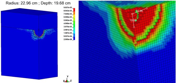
The stress and strain of soil exhibit nonlinear and plastic characteristics. This study triggered an earthquake with an explosion and used the processes of soil deformation and failure to analyze the stress and strain behavior of the soil. The research results showed that the shock wave triggered vibration in the particles on the surface, which altered the stress state of the soil. When the stress exceeded the yield strength of the soil, the stability of the internal structure was disturbed. Furthermore, uneven stress on the soil caused stress concentration, reducing the soil’s shear strength. Failure originated from local plastic deformation. The subsequent plastic deformation and increased displacement were the crucial conditions prompting soil failure. In addition, before soil failure, a shear failure band was formed. When displacement began to increase substantially, the sudden displacement indicated that the soil had failed. The shock wave energy level near the explosion center was high, and the soil bore a high-energy compression wave. The material failed primarily because of tension and compression. Therefore, shear failure is an essential condition of soil failure. The explosion shock wave at the ground surface affected the material’s stability and caused destruction of the medium. Subject to the direct action of the stress wave, plastic deformation occurred outside of the crater, creating a shear failure zone that inflicted irreversible deformation.
4. Conclusions
The compression wave generated by an explosion can affect the stability of geological materials, and the level of destruction is affected by the energy of the shock wave. Shock waves are transmitted through the soil in the form of compression waves. Soil structure and characteristics are destroyed when the strength of the material is exceeded. The ground explosion is mainly based on the transmission characteristics of shock waves in the air and the seismic intensity of a ground surface. The objective of analyzing the amount of destruction caused by a ground explosion is to reduce the damage to the protection target.
Explosions release energy and cause overstress. The instantly generated shock wave affects the stability of the transmission medium. The soil is subjected to a momentary high-stress impact, resulting in stress concentration that damages the original structure and alters the medium’s characteristics. To aid safety protection, this study analyzed the transmission characteristics of overstressed soil and investigated the strain and destruction effects in soil under the impact of transient stress. The research results revealed that the MMALE algorithm can be used to effectively analyze dynamic fluid–solid interaction. Analysis of shock waves inside soil revealed that the process of shock wave transmission changed over time and space. This, in turn, changed the stress state of the material, resulting in particle deformation and displacement. The material structure was destroyed when the shear strain value exceeded the yield strength. The transient overstress increased the shear stress and decreased the shear strength. The displacement and strain increments were used to analyze the stress and plastic strain characteristics of the material and the deformation process of the soil structure. In addition, the displacement and shear strain increments were employed to determine the soil structure destruction area, which can be used to analyze the steady state of soil. The research results may provide a reference for the design of protective soil layers and blast-resistant engineering measures.
References
-
UFC 3-340-02, Structures to Resist the Effects of Accidental Explosions. Department of the Army and Defense Special Weapons Agency, Washington, DC, USA, Ch2, 2008, p. 35-367.
-
Wang Z. Q., Lu Y. Numerical analysis on dynamic deformation mechanism of soils under blast loading. Soil Dynamics and Earthquake Engineering, Vol. 23, Issue 8, 2003, p. 705-714.
-
Tai Y. S., Chu T. L., Hu H. T., Wu J. Y. Dynamic response of a reinforced concrete slab subjected to air blast load. Theoretical and Applied Fracture Mechanics, Vol. 56, 2011, p. 140-147.
-
Jayasinghe L. B., Thambiratnam D. P., Perera N., Jayasooriya J. H. A. R. Blast response and failure analysis of pile foundations subjected to surface explosion. Engineering Failure Analysis, Vol. 39, 2014, p. 41-54.
-
Chafi M. S., Karami G., Ziejewski M. Numerical analysis of blast-induced wave propagation using FSI and ALE multi-material formulations. International Journal of Impact Engineering, Vol. 36, 2009, p. 1269-1275.
-
Wang Z. Q., Hao H., Lu Y. A three-phase soil model for simulating stress wave propagation due to blast loading. International Journal for Numerical and Analytical Methods in Geomechanics, Vol. 28, 2004, p. 33-56.
-
Koga Y., Matsuo O. Shaking table tests of embankments resting on liquefiable sandy ground. Soils and Found, Vol. 30, Issue 4, 1990, p. 162-174.
-
Ma Q., Zhou F., Zhang W., Yuanxun Li Y. An analytical study on blast-induced ground vibration with gravitational effect. Soil Mechanics and Foundation Engineering, Vol. 56, 2019, p. 287-293.
-
Shariatmadari N., Karimpour-Fard M., Shargh A. Evaluation of liquefaction potential in sand-tire crumb mixtures using the energy approach. International Journal of Civil Engineering, Vol. 17, 2019, p. 181-191.
-
Zhang Yijiang, Chen Yumin, Chen Shengshui, Liu Hanlong, Fu Zhongzhi Experimental study on deformation of a sandy field liquefied by blasting. Soil Dynamics and Earthquake Engineering, Vol. 116, 2019, p. 60-68.
-
Kivity Y., Shafri D., Ben Dor G., Sadot O., Anteby I. The blast wave resulting from an accidental explosion in an ammunition magazine. 19th International Symposium on Military Aspects of Blast and Shock Symposium, Canada, 2006.
-
Crandle F. J. Ground vibration due to blasting and its effect upon structures. Journal of the Boston Society of Civil Engineering, Vol. 36, Issue 2, 1949, p. 222-245.
-
Ambrosini D. A., Luccioni B. M. Craters produced by explosions on the soil surface. Journal of Applied Mechanics, Vol. 73, Issue 6, 2006, p. 890-900.
-
Wu C. Q., Hao H. Modeling of simultaneous ground shock and airblast pressure on nearby structures from surface explosions. International Journal of Impact Engineering, Vol. 31, 2005, p. 699-717.
-
Dowding C. H. Blast Vibration Monitoring and Control. Prentice-Hall, Englewood Cliffs, 1985.
-
Ak H., Iphar M., Yavuz M., Konuk A. Evaluation of ground vibration effect of blasting operations in a magnesite mine. Soil Dynamics and Earthquake Engineering, Vol. 29, Issue 4, 2009, p. 669-676.
-
Wang J. Simulation of Landmine Explosion Using LS-DYNA 3D Software: Benchmark Work of Simulation in Soil and Air. DSTO Aeronautical and Maritime Research Laboratory DSTO-TR-1168, 2001.
-
Wang I. T. Field experiments and numerical analysis on the ground vibration isolation of shock wave propagation under explosion shock loading. Vibration, Vol. 2, 2019, p. 300-310.
-
LS-DYNA Theoretical Manual. Livermore Software Technology Corporation, Livermore, CA, USA, 2006.
-
LS-DYNA Keyword User’s Manual. Livermore Software Technology Corporation, Livermore, CA, USA, 2009.
-
Puso M. A., Sanders J., Settgast R., Liu B. An embedded mesh method in a multiple material ALE. Computer Methods in Applied Mechanics and Engineering, Vol. 245, Issue 246, 2012, p. 273-289.
-
Gebbeken N., Ruppert M. On the safety and reliability of high dynamic hydrocode simulations, International Journal for Numerical Methods in Engineering, Vol. 46, Issue 6, 1999, p. 839-851.
-
Dobratz B. M. LLNL Explosive Handbook Properties of Chemical Explosives and Explosive Simulants. Lawrence Livemore National Laboratory Livermore, CA, USA, 1981.
-
Len S. Geomaterial Modeling with LS-DYNA. Livermore Software Technology Corporation, 2001.
About this article

This study was partially supported by the Ministry of Science and Technology, Taiwan, R.O.C. through Grant MOST 107-2221-E-145-001.
