Abstract
To understand the vibration characteristics of rubber track system in traveling, this research studied the small harvester installed with rubber track system and the dynamic model reflecting vibration characteristics of rubber track system on the ground was constructed. Comparing analysis results with measured experimental data obtained from vehicle test, it is proved that the dynamic model established by theoretical analysis can correctly and effectively predict actual movement condition and vibration characteristics of rubber track system, especially at low test vehicle speeds. The relative difference between measured data of vibration acceleration obtained from real vehicle tests and the theoretical value was in the range of –1.2 %-+18.2 %. The vibration prediction and analysis method of rubber tracked vehicle was discussed in this study, and important basic data were provided for the research of comfort evaluation of working posture and lightweight design of rubber tracked mechanism.
1. Introduction
The vehicles installed with rubber track system running gear can get large traction in running, leading to outstanding maneuvering performance and good trafficability. The tracked vehicle for test is not only applicable to agricultural production, but also to complex terrains such as snowfield, intertidal zone, meadow, mountain road, etc. [1]. Besides, domestic diffusion rate of farm mechanization is escalating and crop planted area is enlarging continuously, which raises new requirements on adaptivity of agricultural operation machinery to various complex environments and the stability in efficient working process [2]. Though compared with common wheel-type small harvester, the rubber track system running gear outfitted for the vehicle for test has unideal speed of travel and turning flexibility, yet it has non-replaceable advantages in traveling stability and decreasing harmonic vibrations, etc. Some research takes support wheel of tracked vehicle as object to highlight the factors influencing vehicle vibration by measuring the relation of interaction force between support wheel and track plate [3-5]. And there is also research proving difference in arrangement mode of guide wheel of rubber track system wheel and support wheel will influence vibration acceleration value of test vehicle [6, 7]. In the meanwhile, many investigators also experimented on tractive property of crawler running gear to prove the rubber crawler can release good traction in various topographical conditions [8]. Tire is the most used running gear for various vehicles. Its resistance, traction and driving force in traveling have been researched profoundly [9]. With development of elementary theory of nonlinear mechanics in recent years, the nonlinear vibration resolving has begun to be applied to research on terramechanics of wheeled vehicles with some achievements made [10, 11]. For the rubber track system running gear outfitted with rubber track plate, it is of great importance to use related theories to illuminate the influence of vibration characteristics in running course on vehicle stability [12-14]. The main purpose of this research is to build dynamic model for rubber track system, in the hope of decreasing the harmonic vibrations and increasing operating stability in running of rubber tracked vehicle. The dynamic model herein mainly considers the influence of resistance which has the largest impact on traveling resistance when rubber track system running gear is running at a constant speed on rigid horizontal pavement on roadability, and quantitatively optimizes the result of theoretical analysis, temporarily not considering the influence of soil adhesion on traction and the influence of friction between track plate and ground on traction.
2. Materials and methods
2.1. Structural composition of rubber track system
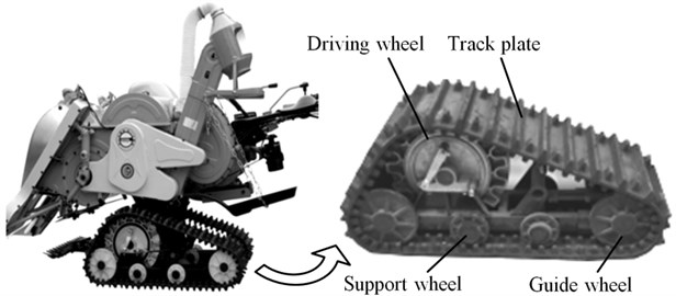
The test vehicle is mainly composed of speed transmission, engine with rubber track system running gear assembled on both sides, as shown in Fig. 1. This rubber track system running gear is mainly composed of revolution driving wheel, triangle frame, support wheel, guide wheel and external rubber crawler, with major parameters as shown in Table 1. In traveling, the mechanism oscillates within certain angle scope with the centre of revolution driving wheel as center of rotation. The amplitude of oscillation can reflect the pavement condition and maintaining of running stability. In front and rear of rubber track system running gear assembled for test vehicle has a guide wheel respectively. Between the guide wheels are arranged 3 support wheels side by side. The guide wheel and support wheel are all installed on triangle frame. Meanwhile, to guarantee crawler tension of rubber track system running gear in running fluctuates within allowable scope, between front guide wheel and triangle frame a tension spring mechanism is installed. The rubber track plate used herein is made of rubber materials, with metal strengthening ribs placed between track plates to enhance intensity of crawler. In running of test vehicle, guide wheel and side-by-side support wheels contact rubber crawler, which will directly influence deformation quantity of rubber track plate with position change of support wheel in the vertical direction. Besides, engine excitation and the unevenness of experimental pavement are prone to cause harmonic vibrations of test vehicle in running on the pavement, leading to poor driving stability [15].
Table 1Main parameters of rubber track system for test
Parameters | Value | parameters | value |
Total length / m | 0.82 | Number of track plate | 28 |
Effective length / m | 0.66 | Arrangement for support wheel | Sequential |
Width / m | 0.3 | Distance between track shoes l/m | 0.036 |
Fig. 1Structural composition of rubber track system
2.2. Construction and analysis of dynamic model for rubber track system
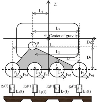
Force analysis of support wheel set is shown in Fig. 3. In the research area of terramechanics for crawler, the interaction force between crawler and support wheel is mainly reflected by the fluctuation of corresponding elastic coefficient and attenuation coefficient, thereby making it possible to measure roadability and vibration characteristics of test vehicle [16]. This research utilizes the fundamentals and experimental model used in above research to structure dynamic model with rubber track system running gear as the specific object. This model is mainly structured based on basic technological parameters of tested vehicle, with center-of-gravity placed at centre of crawler of test vehicle, being a two-dimensional model constructed after comprehensively considering the fluctuation of elastic coefficient and attenuation coefficient of each support wheel of running gear in horizontal direction and vertical direction. The dynamic elasticity coefficients for each rubber track plate of rubber track system running gear are and viscous attenuation coefficients are . The dynamic elasticity coefficient and viscous attenuation coefficient between rubber crawlers show periodical variation and are directly related to vibration frequency of rubber crawler and the position offset . The periodical variation relation can be expressed using Fourier series formula as follows [17]:
Fig. 2Nonlinear variation relationship of coefficient k and coefficient g
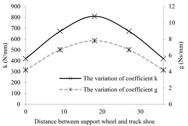
Fig. 3Force analysis of support wheel set
The parameters in the above formula are difficult to be quantitatively measured in experiments. In order to obtain effective test parameters, Fig. 2 is drawn to reflect the nonlinear variation relationship of dynamic elasticity coefficient and viscous attenuation coefficient between support wheel and track plate [18]. As is shown in Fig. 2, when the support wheel is above the track shoe, the coefficient and the coefficient reach the theoretical maximum value, and then reach the minimum value in the middle of two track shoes. In order to simplify the calculation, the coefficient and the coefficient were assumed to be constant in the analysis process. The coefficients took the arithmetic mean of the maximum value and minimum value, which were 600 N/mm and 6 N·s/mm respectively.
In Fig. 3, the displacement of each observing point should be measured quantitatively in --coordinate system [19, 20]. According to measured data, the vertical acting force on position of contact point between support wheel and crawler can be figured out as follows:
The frame of rubber track system was fixed without fulcrum, and test vehicle moved in a straight line on flat artificial surface. Position offset between the supporting wheels and oscillating angle are negligible under the experimental condition. The displacement of contact point in -axis direction and -axis direction was not measured in this experiment because of the difficulty of real-time measurement. Force of support wheel in vertical direction is obtained by approximate calculation according to the shape and mass distribution of the body and the triangle track system. By solving first-order differential equation, the displacement approximation of contact point in -axis direction and -axis direction can be obtained.
When rubber track system moves forward, the support wheel contacts inner side of track plate to produce running resistance in horizontal direction, the fluctuation of magnitude of this running resistance is in direct proportion to the vehicle load. The resistance and the value of correlation coefficient for running resistance show periodic change rule between track shoes [21, 22]. In this dynamic model, the horizontal acting force is required to be calculated if the influence of horizontal acting force between support wheel and rubber track plate on traveling performance is considered. The vertical force for support wheel calculated in above dynamic model is substituted in formula below to calculate the magnitude of horizontal acting force between support wheel and rubber track plate:
Table 2Main parameters for vibration characteristic analysis
Parameters | Value | Parameters | Value |
/ mm·s-1 | 200 400 600 800 1000 1200 1400 1600 1800 2000 | / m | 0.28 |
/ m | 0.22 | ||
/ m | 0.44 | ||
/ kg·m2 | 286 | / m | 0.66 |
/ kg·m2 | 16 | / N·mm-1 | 600 |
0.2 | / Ns·mm-1 | 6 | |
0 | / kg | 72 | |
/ m | 0.18 | / kg | 25 |
/ m | 0.46 | / m | 0.08 |
Then the horizontal and vertical acting force at contacting position of each support wheel and rubber track plate can be obtained quantitatively. With the influence of horizontal acting force not considered, the following horizontal equilibrium equation, vertical equilibrium equation and rotary equilibrium equation about center-of-gravity location of rubber track system can be obtained as follows:
Further improvements on this dynamic model by considering the influence of horizontal acting force on traveling performance of vehicle, horizontal equilibrium equation, vertical equilibrium equation and rotary equilibrium equation about center-of-gravity location of rubber track system can be obtained as follows:
In Eqs. (3)-(14), (1, 2, 3, 4) represents vertical acting force at observing point; (1, 2, 3, 4) represents vertical horizontal acting force at observing point; (1, 2, 3, 4) represents horizontal displacement at observing point; (1, 2, 3, 4) represents vertical displacement at observing point; is angle of oscillation at revolution support point of crawler; is angle of oscillation at centre of gravity of tested vehicle; is horizontal displacement of centre of gravity of tested vehicle; is vertical displacement of centre of gravity of tested vehicle; is mass of tested vehicle (kg); is mass of rubber track system (kg); is running speed of tested vehicle; is position offset between supporting wheels (rad); is static friction coefficient.
To identify the influence of stress between crawler and support wheel on driving stability of agricultural vehicle, this dynamic model established without consideration of the influencing factors such as contact condition between rigid pavement and crawler as well as tension device. The main parameters for the dynamic model of this test are as shown in Table 2.
2.3. Experiment of measuring vibration acceleration of rubber track system running gear
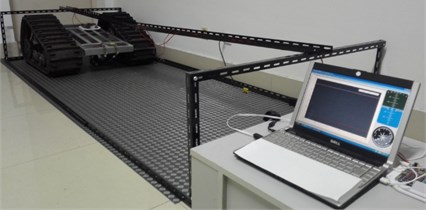
The parameters of test vehicle are shown in Table 1. The purpose of experiment is mainly to measure the fluctuation of vibration acceleration of gravity center of rubber track system running gear in vertical, horizontal and rotational directions with change of ground condition. The rubber track system running gear outfitted with rubber crawler has large contact patch and outstanding shape of grouser, so its tractive property can be exerted on soft pavement such as mire and moor [23]. Considering the fluctuation of vibration acceleration of vehicle on leveled rigid pavement is more regularity and convenient for measurement and comparison, the test of vehicle traveling performance was conducted on indoor ground where PVC rubber sheet was placed. In an effort to accurately measure the vibration acceleration at center-of-gravity position, three-axle acceleration sensors were placed at centre of gravity of test vehicle, and experimental data was recorded and analyzed by MiniIMU which is shown in Fig. 4.
Experiment for the measurement of vibration acceleration is shown in Fig. 5. The influence of small swaying of vehicle from side to side in horizontal direction and vertical direction on measurement of vibration acceleration was not considered in the experimental course. The running distance was 5 m, and running speeds were set as 200 mm/s, 400 mm/s, 600 mm/s, 800 mm/s, 1000 mm/s, 1200 mm/s, 1400 mm/s, 1600 mm/s, 1800 mm/s, 2000 mm/s respectively. The experiment was repeated for 3 times under each running speed to take the average value of measured vibration acceleration for center-of-gravity position in -direction, -direction and angular acceleration, with experimental data recorded. The simulation analysis result of vibration acceleration of vehicle's center of gravity can be obtained by substituting the given parameters to the movement equilibrium equation of test vehicle for comparison with the vibration acceleration measurement data.
Fig. 4Diagram of experimental installation
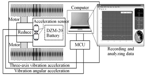
Fig. 5Experiment for the measurement of vibration acceleration
3. Results and discussion
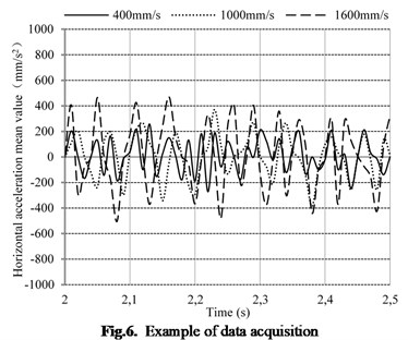
The process of vibration acceleration data acquisition is shown in Fig. 6. During the experiment, the vibration acceleration changes in all directions were recorded real-time after vehicle speed was stable. Averaged the value of maximum acceleration vibration recorded over a period of time, and then compared with the simulation results under the same speed. Then the experimental data was analyzed and arranged, and the changing regularity of vibration acceleration was concluded as a result.
Fig. 6Example of data acquisition
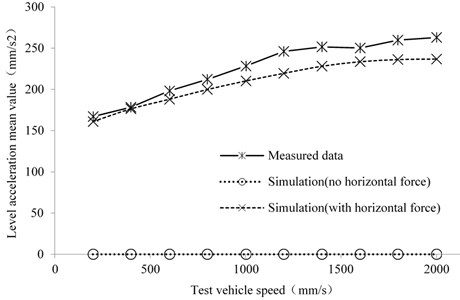
The relationship between horizontal vibration acceleration for centre of gravity of test vehicle and running speed is shown in Fig. 7. With horizontal acting force for centre of gravity not considered, the vibration acceleration in horizontal direction did not show any significant changes and equaled to zero. With horizontal acting force for centre of gravity considered, the horizontal vibration acceleration stepped up with speed increase of test vehicle, and reached peak value within 1600 mm/s-2000 mm/s. The measured horizontal vibration acceleration for centre of gravity in vehicle running test and results of simulation analysis all showed the same fluctuation trend, while the measured vibration acceleration values were all greater than simulation values at each running speed. At low speed, the measured vibration acceleration value was in good agreement with simulation analysis results, while their difference value trends towards increased with speed increase of test vehicle. It is shown that this rubber track system dynamic model can correctly reflect the fluctuation of horizontal vibration acceleration of vehicle at different vehicle speeds based on experimental data analysis. However, the measured data showed certain deviation and fluctuation due to influence of oscillation of vehicle, fluctuation of relative position relation for stress between support wheels and pavement condition. The relative difference between measured data of -axis vibration acceleration obtained from real vehicle tests and the theoretical value was in the range of +1.1 %-+12.1 %. Although the data deviation was small at low speed, but the theoretical value had a great difference with the actually measured data under normal working speed. In this process, repeated tests under the same experiment conditions and calculation of arithmetic mean of experimental data can effectively reduce measuring errors and reflect the true fluctuation of horizontal vibration acceleration.
Fig. 7The relationship between horizontal acceleration and test vehicle speed
The relationship between vertical vibration acceleration for centre of gravity of test vehicle and running speed is shown in Fig. 8. The equilibrium equations were identical under the two simulation conditions, therefore the acceleration calculated in the vertical direction was constant, and there was no direct relation between the horizontal force and the position of contact point. The measured data showed a slow increasing trend with the increase of test vehicle speed, and there was a certain deviation from the theoretical value. The measured data of -axis vibration acceleration obtained from real vehicle tests was larger than the theoretical value at medium and high speed, and the range of difference was between –1.2 % and +3.5 %. It is shown that this rubber track system dynamic model can correctly reflect the fluctuation of vertical vibration acceleration of test vehicle at different vehicle speeds based on experimental data analysis. Considering the influence of motor excitation and contact condition between tracks and ground, the agreement between the theoretical and measured values will be further improved.
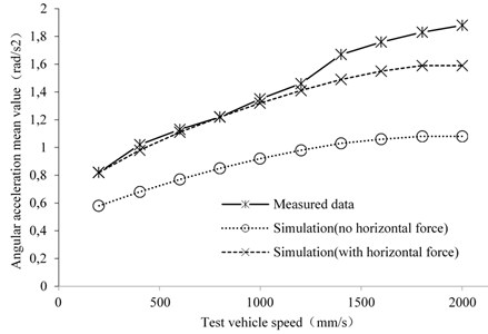
The relationship between angular acceleration for centre of gravity of test vehicle and running speed is shown in Fig. 9. With horizontal acting force for centre of gravity not considered, the angular acceleration showed a slow increasing trend with the increase of test vehicle speed. With horizontal acting force for centre of gravity considered, the angular acceleration also showed an upward trend, and the theoretical value of angular acceleration was relatively large at different speeds. The measured vibration angular acceleration for centre of gravity in vehicle running test and result of simulation analysis all showed the same fluctuation trend, while the measured vibration angular acceleration values were all greater than simulation values at each running speed. Effectiveness and validity of rubber track system dynamic model are verified through experimental data analysis and result comparison, and can reflect the fluctuation of vibration angular acceleration of test vehicle at different speeds correctly. At low speed, the measured angular acceleration and value of simulation analysis were close. However, the experimental data deviated from the calculated data when test vehicle was moving at medium and high speed. The measured data showed certain deviation and fluctuation due to the swing of the vehicle in all directions, road surface excitation and motor excitation on both sides. The relative difference between measured data of vibration angular acceleration obtained from vehicle tests and the theoretical value was in the range of +0.1 %-+18.2 %. Although the data deviation was small at low speed, but the theoretical value had a great difference with the actually measured data under normal working speed. Although the dynamic model can reflect the changing characteristics of the vibration acceleration of the triangle track system to a certain extent, this simplified model still needs further modification and improvement in subsequent studies.
Fig. 8The relationship between vertical acceleration and test vehicle speed
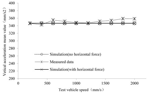
Fig. 9The relationship between angular acceleration and test vehicle speed
4. Conclusions
To understand the vibration characteristics of rubber track system in traveling, this research conducted simulation analysis and real vehicle experiment with vehicle installed with rubber track system running gear as object. The comparative analysis on measured experimental data and simulation analysis verified the effectiveness and correctness of dynamic model. In the meanwhile, the simulation analysis results indicated that the interaction force between support wheel and track plate in horizontal direction was directly related to the fluctuation magnitude of horizontal vibration acceleration, vertical vibration acceleration and angular acceleration of vehicle’s center of gravity. The crawler dynamic model considering the influence of horizontal acting force of centre of gravity can reflect the vibration characteristics of tracked vehicle to a certain extent. The measured data and simulation analysis results had deviation to some degree due to the influence of oscillation of vehicle, fluctuation of relative position between support wheels and pavement condition as well as data collection method in the test. It is needed to improve test method and use the rubber crawler dynamic elasticity coefficients and viscous attenuation coefficients obtained in actual measurement as well as other parameters to get more precise experimental data. The subsequent simulation experiment will be conducted with consideration of settlement of support wheel set towards inner side of rubber track plate and define the key parameters in contact setting, etc. to structure dynamic model which can more precisely predict vibration characteristics of rubber track system, thereby provides more important basic data for the research of comfort evaluation of working posture and lightweight design of rubber tracked mechanism.
References
-
Yang L. H., Wang S. J., Wang Y. J. Status and developing tendency of tracked wheel conversion technology. Development and Innovation of Machinery and Electrical Products, Vol. 24, Issue 2, 2015, p. 80-82.
-
Tang J. H., Lin J. Y., Liu C. W., et al. Path analysis of influencing factors on agricultural mechanization development in China. Journal of Liaoning Technical University (Natural Science), Vol. 30, Issue 2, 2011, p. 312-315.
-
Yan Z. H., Wang G. Q., Yao Z. W., et al. Contact analysis on huge crawler track wheel and track pad. Transactions of the Chinese Society of Agricultural Engineering, Vol. 28, Issue 17, 2012, p. 51-56.
-
Su B. C. Contact characteristics analysis of track plate and crawler walking machine roller based on finite element analysis. Coal Mine Machinery, Vol. 35, Issue 8, 2014, p. 107-109.
-
Zhang J. Z., Wang Q., Jin Q. C., et al. Analysis and simulation of acting mechanical parameters of triangular track mechanism and ground based on Bekker theory. Agro Food Industry Hi-Tech, Vol. 28, Issue 1, 2017, p. 3126-3220.
-
Mitsuoka M., Inoue E., Hara S., et al. Vibration characteristics and identification of dynamic parameters of agricultural rubber crawler vehicle. Terramechanics, Vol. 24, Issue 1, 2004, p. 95-100.
-
Inoue E., Ma R., Mitsuoka M. Investigation of nonlinear vibration characteristics of agricultural rubber crawler vehicles. Agricultural Mechanization in Asia Africa and Latin America, Vol. 42, Issue 1, 2011, p. 89-93.
-
Grisso R., Perumpral J., Zoz F. An empirical model for tractive performance of rubber-tracks in agricultural soils. Journal of Terramechanics, Vol. 43, Issue 2, 2006, p. 225-236.
-
Yu Q. X. Present situation and development of ORT tires. China Rubber/Plastics Technology and Equipment, Vol. 40, Issue 1, 2014, p. 5-19.
-
Yang X. Nonlinear dynamics and lateral stability of tractor semi-trailer vehicle. Journal of Mechanical Engineering, Vol. 48, Issue 8, 2012, p. 78-83.
-
Yang X., Xiong J. Nonlinear yaw dynamics analysis and control for the tractor-semitrailer vehicle. International Journal of Heavy Vehicle Systems, Vol. 20, Issue 3, 2013, p. 253-288.
-
Kim B. S., Spiryagin M., Hong H. Y., et al. Analysis of the effects of main design parameters variation on the vibration characteristics of a vehicle sub-frame. Journal of Mechanical Science and Technology, Vol. 23, Issue 4, 2008, p. 960-963.
-
Peng Y. U., Chen F. F., Zhang T., et al. Vibration characteristics analysis of a central-driven electric vehicle powertrain. Journal of Vibration and Shock, Vol. 34, Issue 1, 2015, p. 44-48.
-
Jiang G. P., Wang G. L., Zhou K. K. Experimental research on vibration characteristics of the agricultural vehicle. Journal of Jiangsu University of Science and Technology, Vol. 22, Issue 4, 2001, p. 36-40.
-
Zhang Z. W., Yang F. Z., Zhang Z. P. Analysis on driving stability of caterpillar tractor on ramp. Agricultural Equipment and Vehicle Engineering, Vol. 11, Issue 1, 2010, p. 7-10.
-
Inoue E., Sakai J., Inaba S. Basic studies on vibration characteristics of the rubber crawler system for farm machinery (Part 3). Journal of JSAM, Vol. 52, Issue 5, 1990, p. 11-18.
-
Inoue E., Sakai J., Inaba S. Basic studies on vibration characteristics of the rubber crawler system for farm machinery (Part 2). Journal of JSAM, Vol. 52, Issue 4, 1990, p. 29-36.
-
Mitsuoka M., Inaba S., Inoue E., et al. Investigation of the nonlinear interaction between a track roller and an agricultural rubber crawler. Journal of JSAM, Vol. 70, Issue 5, 2008, p. 48-54.
-
Zhang Y., Chen L. Y., Luo W. D. Simulation of off wheel problem of high speed tracked vehicle based on Recurdyn. Coal Mine Machinery, Vol. 35, Issue 2, 2014, p. 49-51.
-
Zhang T., Guo Z. Q., Zhou Z. L. Simulation and analysis of dynamic model and wheel removal problem of rubber tracked vehicle running system. Journal of Henan University of Science and Technology (Natural Science), Vol. 27, Issue 6, 2006, p. 12-15.
-
Inaba S., Inoue E., Hashiguchi K., et al. Travel resistance of the agricultural rubber crawler (part 2): analytical simulation of travel resistance caused by rolling resistance of the track rollers. Journal of the Japanese Society of Agricultural Machinery, Vol. 62, Issue 2, 2000, p. 81-86.
-
Inaba S., Inoue E., Hashiguchi K., et al. Travel resistance of the agricultural rubber crawler (part 3): inspection of the travel resistance simulation based on the measurement of the load acting on the track rollers. Journal of the Japanese Society of Agricultural Machinery, Vol. 65, Issue 1, 2003, p. 99-105.
-
Hou Z. M., Yao K., Wang S. J. Development and application of convertible rubber track wheel. China Rubber Industry, Vol. 56, Issue 12, 2009, p. 764-767.
About this article

