Abstract
This paper presents the design approach of Generalized Dynamic Inversion (GDI) for angular position control of SRV02 rotary servo base system. In GDI, linear first order constraint differential equations are formulated based on the deviation function of angular position and its rate, and its inverse is calculated using Moore-Penrose Generalized Inverse to realize the control law. The singularity problem related to generalized inversion is solved by the inclusion of dynamic scaling factor that will guarantee the boundedness of the elements of the inverted matrix and stable tracking performance. Numerical simulations and real-time experiment are performed to evaluate the tracking performance and robustness capabilities of the proposed control law considering nominal and perturbed model dynamics. For comparative analysis, the results of GDI is compared with conventional PID control. Simulation and experimental results demonstrate better angular position tracking for the square-wave and sinusoidal waveforms, which reveals the superiority, and agility of GDI control over conventional PID.
1. Introduction
Servomotor based on rotary cart system is essential for the modern-day industries and a powerful tool for real world applications. Depending upon the type of production plant, position and speed control of servo system can be of major importance. They are extensively used in electrical vehicles, robotic manipulators, automated factories, aircrafts, etc. [1] because of its accuracy, reliability, low cost, less power utilization, and compatibility with digital systems [2]. The high precision required in position tracking is very crucial for evaluating the performance of servo motor system. Inaccurate position tracking will lead to experimental failure, such as bad tracking properties of actuators will affect the stability of entire missile control system. Therefore, it is imperative to develop the control algorithms to improve the tracking performance and accuracy of servo motor systems. The inherent attributes of servo motors such as parametric uncertainties, load inertial torque, nonlinear friction, load variations and torque disturbances impose more complications and challenges to design the precise tracking control system [3].
To solve these challenges, several control methods are proposed in literature to eliminate the influences of the above factors. Linear control technique such as Proportional Integral Derivative (PID) [4], and Linear Quadratic Regulator (LQR) [5], are efficient, however their performance might deteriorate due to nonlinearities and parametric uncertainties. Therefore, to design effective tracking control system, several nonlinear control techniques are considered such as Back stepping control [6, 7], Adaptive control [8, 9], Fuzzy control [10, 11], Neural networks [12]. Furthermore, Sliding mode controllers [13-15] are used extensively for servo motor control applications, because of its inherent robustness characteristics. However, the influence of chattering on the control signal is inevitable and therefore the selection of controller gain is a trade-off between smooth control action and tracking control accuracy. Besides these, state feedback based Fractional order controller is also designed for better tracking performance of servo cart system [16-18].
Among nonlinear control, Generalized Dynamic Inversion (GDI) is a constraint based control approach, in which rather to invert the entire system equations of motion, dynamic constraints are defined which contains the control objectives and are inverted using Moore-Penrose Generalized Inverse (MPGI) based Greville method [19]. Hence GDI methodology overcome the limitations associated with classical Nonlinear dynamic inversion control, which includes cancellation of useful nonlinearities, simplifying assumptions required to invert the nonlinear plant dynamics, large control effort and square dimensionality restrictions. GDI control technique had been applied for several aerospace and robotics applications [20-26].
In this paper, GDI control is applied for the angular position tracking of SRV02 rotary servo base system. It begins with prescribing the set of linear first order constraint differential equations which encompasses the essential control objectives. The constraint dynamics are evaluated along the trajectories of angular position and its rate and are inverted using MPGI based Greville method to obtain the control law. The singularity problem is addressed by including a first order asymptotically stable dynamic scaling factor in the expression of MPGI. To evaluate the performance of GDI control, numerical simulations and real time experiment are performed on Quanser’s SRV02 servo base system, to analyze the tracking capabilities of GDI control law.
The remaining part of the paper is organized as follows: The mathematical modeling of SRV02 rotary servo base system is presented in Section 2. The formulation of constraint dynamics in the form of differential equations for angular position control using GDI is discussed in Section 3. The inclusion of dynamic scale factor to deal with the singularity problem associated with GDI is shown in Section 4. The semi-global partial closed loop stability of GDI control is presented in Section 5. Numerical simulations and experimental results are discussed in Section 6, whereas conclusion is presented in Section 7.
2. Mathematical modeling
The SRV02 rotary servo base system provides hardware in loop experimental research platform for rapid prototyping of real-time control. This platform is designed for position and speed control applications and being utilized to validate the performance of various control algorithms. In this section, the dynamical modeling of SRV02 servo system is presented. The schematic diagram of a SRV02 rotary servo base unit is shown in Fig. 1 [27]. In the schematic diagram, the electrical circuit elements , , and are denoted for motor resistance, inductance, back-emf and back-emf constant respectively. Angular positions, speeds and torques are expressed by , , and , , respectively for the motor shaft and the load shaft of rotary servo base unit. The parameters and represents the gear number of teeth, whereas moment of inertia and viscous friction coefficients are considered as , and , for the motor and load shaft respectively.
Fig. 1Schematic diagram of a SRV02 servo base unit
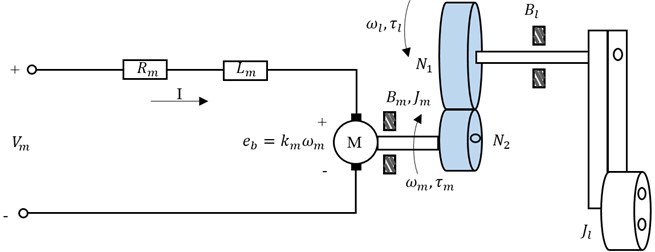
The electrical and mechanical dynamical equations are combined to obtain the expression of the angular speed of the load shaft with respect to the applied input voltage of the motor, resulting in:
where represents equivalent moment of inertia and is the equivalent damping term and is expressed as:
where, represents the equivalent viscous friction, is the gear ratio, is the efficiency of the gearbox, is the efficiency of the motor, is the motor torque constant and denotes the actuator gain, defined as:
3. Design of GDI control
The autopilot for angular position control of SRV02 rotary servo base unit is based on GDI. The dynamical equations of SRV02 servo system given by Eqs. (1-2) can be expressed as:
where and . To precisely tracks the angular position and the angular velocity, the squared error norms of the state deviation functions are defined as:
where and . In Eqs. (5-6), and are the positive real valued constants, the letter denotes the error of the corresponding state from its desired value, and the subscript represents the desired value. Based on the deviation functions, linear time varying ordinary differential constraint equations are formulated, whose differential orders are equivalent to the relative degree of the deviation functions. The equation takes the following form:
where the coefficients , and are selected appropriately, such that the constraint differential equations given by Eqs. (7-8) are uniformly asymptotically stable [28]. The first and second time derivatives of constraint dynamics given by Eq. (7) are calculated as:
Similarly, the first-time derivative of constraint dynamics given by Eq. (8) is computed as:
By placing the time derivatives given by Eqs. (9-11) in the constraint dynamics described by Eqs. (7-8), its differential forms are transformed into an algebraic expression, given as:
or:
where:
Eq. (13) is an under-determined algebraic system having infinite number of solutions. These solutions can be parameterized by generalized inversion using the Greville method, which yields:
where is the MPGI of given as:
and is the null control, and is the null projection given by:
The matrix appeared to be a tall matrix, which causes the element of becomes zero by using the property of pseudo inverse 1. Hence the null control is supposed to be incompetent and therefore not considered in the present control design methodology.
Generalized inversion has its limitations when it is applied to matrices with variable elements due to the singularity problem. This problem arises when the inverted matrix tends to change its rank, which causes discontinuity in the MPGI matrix function, and causes the elements to go unbounded. In this paper, dynamic scale factor is augmented within MPGI to address the problem of singularity.
4. GDI singularity avoidance
For singularity avoidance, a linear first order dynamic scaling factor is introduced within MPGI [21], defined as:
The homogeneous part of Eq. (21) is asymptotically stable, whereas in the forcing term is a positive real valued constant. The Dynamically Scaled Generalized Inverse (DSGI) is written as:
Based on this, the updated GDI based control input voltage is given as:
and the closed loop dynamics given by Eq. (4) is therefore expressed as:
Theorem 1. For the closed loop systems depicted by Eq. (3) and Eq. (24), the elements of are always bounded for all .
Proof. As time tends to infinity, the asymptotically stable first order dynamics given by Eq. (21) satisfies:
Hence:
In reference to Eq. (26), as is positive definite, so the inverse of is definitely exist if the right part of Eq. (25) is finite and non-zero. However, the inverse exists for the two limit conditions still need to be verified given as:
If the first limit condition holds true then Eq. (26) implies that:
If the second limit condition is satisfied then Eq. (26) yields:
which indicates that the control input voltage given by Eq. (23) approaches to given by Eq. (18) showing that the constraint dynamics given by Eqs. (7-8) are asymptotically stable as the elements of are bounded. Nevertheless, asymptotic realization of Eqs. (7-8) implies that the error vector asymptotically vanishes, which contradicts the second limit condition of Eq. (27). Therefore, occurrence of the second limit condition is impossible.
5. Global practical asymptotic stability of GDI
The semi-global asymptotic stability of the constraint dynamics given by Eqs. (7-8) are guaranteed by the control input voltage given by Eq. (18). This yields that the equilibrium error state of the solution trajectories of the MPGI-based closed loop dynamics given by Eqs. (3-4) from the desired solution trajectories is asymptotically stable concerning [9]. The similar attribute is applicable on the equilibrium error state that corresponds to the DSGI based closed-loop dynamics given by Eq. (3) and Eq. (24) which is stated by the following theorem.
Theorem 2. Consider the closed loop systems given by Eq. (3) and Eq. (24), the error vector remains bounded for all 0, which ensures that the equilibrium error vector is globally practical stable.
Proof. On the contrary assuming that the error vector goes unbounded, then it follows from the asymptotically stable dynamics of dynamic scale factor given by Eq. (25) that:
Under this assumption, the DSGI of is written as:
which results in the asymptotic realization of the constraint dynamics given by Eqs. (7-8). This statement is contradictory with the statement in which unboundedness of error vector is assumed.
In a similar way, if error vector turns to zero, then the DSGI of implies that:
Accordingly, the elements of the error vector are always confined which illustrates that the equilibrium error state is globally attractive. Moreover, the DSGI based control voltage enforces the error trajectories in the close vicinity of the equilibrium error vector which makes it uniformly ultimate bounded, i.e., making it globally practical stable.
6. Numerical simulations and experimental results
To analyze the efficiency and the tracking performance of the GDI control, numerical simulations and experimental studies are performed on Quanser’s SRV02 servo system, whose major parameters along with the numerical values are listed in Table 1 [27].
Table 1Quanser’s SRV02 servo system specifications
Parameters | Values | Units |
Motor armature resistance, | 2.6 | Ω |
Motor viscous damping coefficient, | 0 | Nm/(rad/s) |
Load viscous damping coefficient, | 4.41e-6 | Nm/(rad/s) |
Total gear ratio, | 70 | – |
Motor armature inductance, | 0.18 | mH |
Motor current-torque constant, | 7.68 e-3 | Nm/A |
Motor back-emf constant, | 7.68 e-3 | V/(rad/s) |
Rotor moment of inertia | 3.9 e-7 | Kg m2 |
Gear moment of inertia, | 9.76 e-5 | Kg m2 |
Gear viscous damping, | 0.015 | Nm/(rad/s) |
Maximum input current, | 1 | A |
Maximum motor speed, | 628.3 | rad/s |
In the simulations, the design parameters of the proposed GDI control law are selected as 10, 1, 10, 12000, 60.
6.1. Square-wave tracking
In the first scenario, the servo system is required to follow the square-wave profile having amplitude of ±1 deg and a frequency of 0.4 Hz. The position tracking performance of GDI control by considering nominal servo system parameters is shown in Fig. 2(a), which indicates that the GDI control exhibits fast and accurate angular position tracking. The error convergence in the form of squared error norm is shown in Fig. 2(b). The controlled input voltage generated to perform the required maneuvering is shown in Fig. 2(c), whereas the desired and achieved angular speeds are shown in Fig. 2(d).
Fig. 2Square-wave tracking
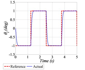
a) Angular position tracking
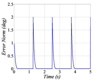
b) Squared error norm
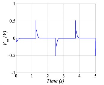
c) Input voltage
d) Angular speed tracking
6.2. Robust analysis for Sinusoidal positional tracking
In this plot, a sinusoidal waveform having an amplitude of ±20 deg with a frequency 0.2 Hz is provided as the reference profile. To evaluate the robustness characteristics, the variations of 20 % in the numerical values of SRV02 system parameters are also considered. Comparative analysis of GDI is also performed with PID control scheme. The angular position tracking of the given sinusoidal trajectory is shown in Fig. 3(a), which clearly demonstrate the better tracking performance of the GDI control in comparison with PID. The squared norms of the angular position errors are depicted in Fig. 3(b), in which the error goes up to 1.5 deg by using PID control, however by employing GDI control, the error value reaches approximately 0.15 deg, which is 10 times lesser in magnitude as compared to PID, that obviously established the superiority and agility of the proposed GDI based control law. The generated control input voltages for sinusoidal angular positional tracking are shown in Fig. 3(c) which exhibit that the control input requirement is very much realizable. The initial small overshoot in the control voltage command generated by GDI, is because of the fast convergence of positional tracking error. The tracking performance of angular speeds are shown in Fig. 3(d).
Fig. 3Sine position tracking
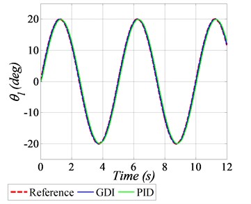
a) Angular position tracking
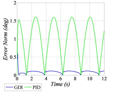
b) Squared error norm
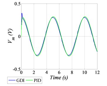
c) Input voltage
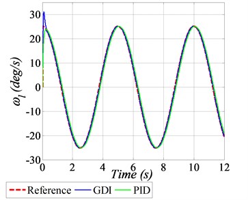
d) Angular speed tracking
6.3. Experimental results
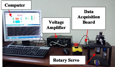
The performance of the GDI control law is also established through experimental results, conducted on a laboratory test bed Quanser’s SRV02 rotary servo base system. The experimental setup includes a Computer, the Rotary Servo Unit (SRV02) equipped with DC motor, gearbox, load, rotary arm and encoder, Linear Voltage Amplifier (VoltPAQ-X1) and Data Acquisition Board (G2-USB) as shown in Fig. 4.
Fig. 4Experimental setup
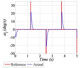
For real-time experiment, a sinusoidal trajectory of ±40 deg peak to peak amplitude with the frequency of 0.2 Hz is considered as a reference profile. Furthermore, to evaluate the robustness of GDI control, +10 % variations in the numerical values of system dynamical parameters are also assumed. The angular position tracking performance, subject to parametric uncertainties is shown in Fig. 5(a), whereas the squared error norm of the angular position is given in Fig. 5(b). The generated control input voltage and the tracking of angular speed are shown in Fig. 5(c) and 5(d) respectively.
Fig. 5Experiment results
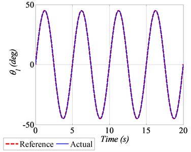
a) Angular position tracking
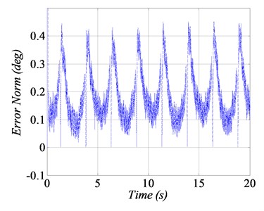
b) Squared error norm
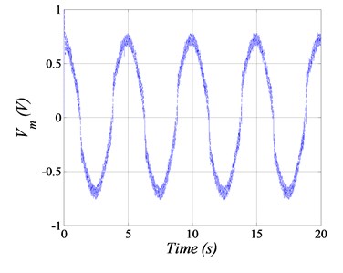
c) Input voltage
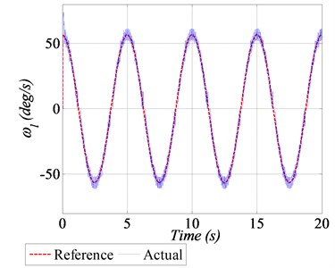
d) Angular speed tracking
7. Conclusions
This paper successfully demonstrates the design of GDI control for angular position control of SRV02 rotary servo base system. In GDI control, dynamic constraints are successfully prescribed in the form of constraint differential equations and are inverted using MPGI to realize the control law for stable position tracking. The singularity problem is addressed successfully by augmenting a delaying dynamic scale factor in the definition of MPGI. To demonstrate the effectiveness of proposed GDI control, a dynamic model of servo cart system is developed, and numerical simulations are conducted considering both nominal and perturbed dynamical model. In addition to computer simulations, real time experiment is also performed on Quanser’s SRV02 rotary servo base system in presence of parametric uncertainties. Computer simulation and experimental results exhibit better angular position tracking performance of the GDI control law for the square-wave and sinusoidal trajectories.
References
-
Li G. M., Tsang K. M. Concurrent relay-PID control for motor position servo systems. International Journal of Control, Automation and Systems, Vol. 5, Issue 3, 2007, p. 234-242.
-
Galgamuwa G. I. R. K., Liyanage L. K. G., Ekanayake M. P. B., Samaranayake B. G. L. T. Simplified controller for three wheeled omni directional mobile robot. 10th International Conference on Industrial and Information Systems, 2015, p. 314-319.
-
Ramírez G. V. G., Valdés L. G. V., Medina M. A., Beltrán C. D. G., López C. A. V. Adaptive nonlinear control of induction motor. International Journal of Control, Automation and Systems, Vol. 9, Issue 1, 2011, p. 176-186.
-
Rathore N. S., Chauhan D. P. S., Singh V. P. Tuning of PID controller for position control of DC servo motor using Luus-Jaakola optimization. International Conference on Computer, Communication and Control, 2015.
-
Zadeh F. K., Moallem P., Asiri S., Zadeh M. M. LQR motion control and analysis of a prototype spherical robot. 2nd RSI/ISM International Conference on Robotics and Mechatronics, 2014, p. 890-895.
-
Payam A. F., Dehkordi B. M. Nonlinear sliding-mode controller for sensorless speed control of DC servo motor using adaptive back stepping observer. International Conference on Power Electronics, Drives and Energy Systems, 2006.
-
Liu D. P., Sun Q. M. A nonlinear servo control method based on integral backstepping scheme. Proceedings of International Conference on Machine Learning and Cybernetics, 2005, p. 479-481.
-
Tendero Reas R.-Y., Reas R. D. Study of an adaptive servo control using adaptive filtering scheme. 2nd International Conference on Control, Automation and Robotics, 2016, p. 154-158.
-
Buciakowski M., Witczak M., Korbicz J. Adaptive fault tolerant control: Application to a DC servo motor. 20th International Conference on Methods and Models in Automation and Robotics, 2015, p. 800-805.
-
Dursun E. H., Durdu A. Position control by using PD type fuzzy logic: experimental study on rotary servo system. 8th International Conference on Electronics, Computers and Artificial Intelligence, 2016.
-
Wei Y., Xu J., Zhu T. Fuzzy control in the DC motor servo system for gravimeter stabilized platform. International Conference on Electrical Machines and Systems, 2013, p. 1052-1055.
-
Oniz Y., Kaynak O., Abiyev R. Spiking neural networks for the control of a servo system. IEEE International Conference on Mechatronics, 2013, p. 94-98.
-
Kommuri S. K., Shafiq G., Rath J. J., Veluvolu K. C. Robust control of DC motor drives using higher-order integral terminal sliding mode. 14th International Conference on Control, Automation, Robotics and Vision, 2016.
-
Chuei R., Cao Z., Man Z. Sliding mode based repetitive control for parameter uncertainty of a brushless DC servo motor. International Conference on Advanced Mechatronic Systems, 2016, p. 62-67.
-
Qureshi M. S., Swarnkar P., Gupta S. Assessment of DC servo motor with sliding mode control approach. 1st International Conference on Control, Measurement and Instrumentation, 2016, p. 351-355.
-
Al Saggaf U.-M., Mehedi I. M., Mansouri R., Bettayeb M. State feedback with fractional integral control design based on the Bode’s ideal transfer function. International Journal of Systems Science, Vol. 47, Issue 1, 2016, p. 149-161.
-
Bettayeb M., Mansouri R., Al Saggaf U., Mehedi I. M. Smith predictor based fractional-order-filter PID controllers design for long time delay systems. Asian Journal of Control, Vol. 19, Issue 2, 2017, p. 587-598.
-
Al Saggaf U.-M., Mehedi I. M., Mansouri R., Bettayeb M. Rotary flexible joint control by fractional order controllers. International Journal of Control, Automation and Systems, Vol. 15, Issue 6, 2017, p. 2561-2569.
-
Greville T. N. E. The pseudo inverse of a rectangular or singular matrix and its applications to the solutions of systems of linear equations. SIAM Review, Vol. 1, Issue 1, 1959, p. 38-43.
-
Ansari U., Bajodah A. H., Alam S. Generalized dynamic inversion based attitude control of autonomous underwater vehicles. IFAC-Papers Online, Vol. 49, Issue 23, 2016, p. 582-589.
-
Ansari U., Bajodah A. H. Robust generalized dynamic inversion quadrotor control. The 20th World Congress of the International Federation of Automatic Control, Toulouse, France, 2017.
-
Ansari U., Bajodah A. H. robust generalized dynamic inversion control of autonomous underwater vehicles. The 20th World Congress of the International Federation of Automatic Control, Toulouse, France, 2017.
-
Ansari U., Bajodah A. H. Robust generalized dynamic inversion based control of autonomous underwater vehicles. Proceedings of the Institution of Mechanical Engineers, Part M: Journal of Engineering for the Maritime Environment, 2017, https://doi.org/10.1177/1475090217708640.
-
Ansari U., Bajodah A. H. Guidance and robust generalized inversion based attitude control of satellite launch vehicle. 4th International Conference on Control Engineering and Information Technology, Hammamet, Tunisia, 2016.
-
Ansari U., Bajodah A. H. Robust launch vehicle’s generalized dynamic inversion attitude control. Aircraft Engineering and Aerospace Technology, Vol. 89, Issue 6, 2017, p. 902-910.
-
Ansari U., Bajodah A. H., Hamayun M. T. Quadrotor control via robust generalized dynamic inversion and adaptive non-singular terminal sliding mode. Asian Journal of Control, 2019, https://doi.org/10.1002/asjc.1800.
-
Quanser SRV02. User Manual. Quanser Inc., 2009.
-
Hameduddin I., Bajodah A. H. Nonlinear generalized dynamic inversion for aircraft maneuvering control. International Journal of Control, Vol. 85, Issue 4, 2012, p. 437-450.
Cited by
About this article

This article was funded by the Deanship of Scientific Research (DSR), King Abdulaziz University, Jeddah. Therefore, the author acknowledges with thanks DSR financial support.
