Abstract
In order to analyze the integral forced performance of external prestressing and carbon fiber reinforced beam, the analytical solution of the carbon fiber-concrete composite beams under the vertical concentrated load and external prestressing was derived in this article based on the classical theory of elasticity and contact. The deflection curve equation and the transverse distributing influence lines of simply supported beam after the joint reinforcement were obtained based on the eccentric compression method, and the results of simply supported beams with or without joint reinforcement were compared. The results show that the integral forced performance of external prestressing and carbon fiber reinforced beam was effectively improved, and the new calculation method of transverse distribution factors has a practical value.
Highlights
- Analyzed the integral forced performance of external prestressing and carbon fiber reinforced beam.
- The analytical solution of the carbon fiber-concrete composite beams under the vertical concentrated load and external prestressing was derived.
- The deflection curve equation and the transverse distributing influence lines of simply supported beam after the joint reinforcement were obtained.
1. Introduction
Due to the limitation of technology level and the increase of traffic load, and a certain degree of damage generated in a part of bridges, the bearing capacity is reduced, and a large number of dangerous old bridges emerge takes place [1]. Therefore, in order to protect people’s lives and property safety, a proper reinforcement for these damaged bridges structure to improve their bearing capacity becomes the primary task in bridge maintenance in our country at present. Joint reinforcement is a new method of reinforcement put forward on the basis of traditional strengthening methods such as externally prestressing reinforcement, carbon fiber reinforcement and stick steel reinforcement [2-4]. Joint reinforcement has higher reliability, security, and thus becomes the subject of active research of bridge repair and reinforcement [5].
Wen-Ping Xu [6] has had an experimental research of stick steel-external prestressing reinforcement, structural characteristics such as ultimate bearing capacity and crack width of concrete T beam were compared with those with the stick steel reinforcement, external prestressing and stick steel-external prestressing respectively. Test results were as follows: the strengthening effect of joint reinforcement is “1 + 1 > 2”; Wei Lu [7] has studied carbon fiber cloth-external prestressing reinforcement. Mechanics regularity of joint reinforcement beam was got by the research of T beam reinforced with carbon fiber, external prestressing and carbon fiber- external prestressing respectively. The results were as follows: When beam reinforced with carbon fiber- external prestressing is under the force, the utilization rate of carbon fiber is higher than the utilization rate of external prestressing tendons, the carbon fiber cloth makes a greater contribution in the early stage, and the external prestressing tendons will be studied more later. Their researches show that the joint reinforcement has a certain engineering application value. It is of great significance to study the joint reinforcement. And some studies on the forced performance of strengthened beams have been done.
Bolduc [8] has studied the influence of fatigue loading, prior cracking and patch materials on flexural performance of reinforced concrete members retrofitted with externally bonded CFRP plates. And many available test data are obtained through retrofitting and testing of a 18.3 m (60 ft) pre-stressed box girder retrofitted with CFRP composite plates with mechanical anchors. Choi [9] conducted an experiment of effective stresses of concrete beams strengthened using carbon-fiber-reinforced polymer and external prestressing tendons. The effective stress of the RC beams was estimated by analyzing the experimental reinforcing effect and the resulting behavior of each specimen. It was found that the strengthening effect of CFRP was affected by the initial damage in the RC beams. On the other hand, in external post-tensioning, application of strain induced by an initial effective stress in the RC beams. As a result, the effective stress of these RC beams was reduced, and their performance was improved. Han [10] has highlighted that the external prestressing method was limited for strengthening by that it is hard to make the external anchorage with big load carrying capacity, and the fiber strengthening method was also limited by the volume of reinforcement. Therefore, a new strengthening method of PSC girder using external prestressing and glass fiber was proposed. For this study, Han accomplished field tests which assess the load carrying capacity before and after strengthening using external prestressing and glass fiber reinforcement, also various values were measured when external tendons were pre-stressed. As a result, the ultimate load carrying capacity of the bridges, which were reinforced with external tendons and glass fiber, was higher than the original designed internal force of the bridges. Their experiments deeply studied the forced performance of external prestressing and carbon fiber reinforced beam and laid the foundation for a theoretical analysis.
The research results of the joint reinforcement methods mentioned above provided an important reference for a further research, nevertheless these studies were mainly concentrated on the experimental research and gave a little reliable spatial analysis and design theory of the bridge superstructure after reinforcement. Based on the above study background, the joint reinforcement theory of external prestressing and carbon fiber reinforcement was studied in this paper, the analytical solutions of beam after being reinforced with external prestressing and carbon fiber were derived, the transverse distribution coefficient of girder after joint reinforcement was solved, and the influence of pre-stressed steel and carbon fiber on the overall mechanical performance of the main girder was obtained, the design theory of this paper can be effectively used to calculate the displacement and stress state of the main girder of the bridge strengthened with the external pre-stress method. It can provide a theoretical basis for the engineering application.
2. Basic assumptions
According to the actual deformation and stress state of reinforced beam, the basic assumptions used in this article are as follows [11, 12]: (1) Concrete beam accords with flat section assumption; (2) Carbon fiber cloth bears axial force only; (3) There is slip strain difference at the interface of carbon fiber cloth and concrete beam, and the shear stress transferred at interface is proportional to the displacement difference of carbon fiber cloth and concrete beam; (4) External pre-stressed tendons have common deformation with a composite beam at the anchor point, and the stress and strain of prestressed tendons has a linear relationship; (5) The stiffness of crossbeam at the min-span is infinite, and the deformation of mid-span section is a straight line under load; (6) The load assigned to each beam is proportional to the deflection; (7) The torsional effect of the main girder is ignored.
3. Basic equation of composite beam after carbon fiber affixing
3.1. Displacement function of composite beam
Because the deformation of concrete and carbon fiber is incoordinated [13], there are three basic unknown functions of the beam displacement after reinforcement, namely: , , . Where , are the axial displacements of concrete beam and carbon fiber cloth at section, respectively. is the vertical displacement of composite beam. The vertical lift effect of composite beam was not considered, so .
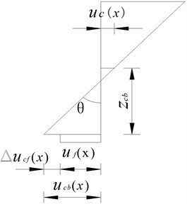
According to Fig. 1, the displacement function expressions of composite beam after pasting carbon fiber are given as:
where is the axial displacement of concrete beam at the centroid section; is the deflection angle at section ; is the distance from the centroid section of concrete beam to interface at the beam bottom, is negative under the section centroid, otherwise it is positive.
is the sliding displacement difference between the concrete beam and carbon fiber cloth, according to Eq. (1):
Fig. 1Cross-sectional displacement of composite beam
3.2. Geometric equations of composite beam
1) By the elastic mechanics, the relationships between the displacement and strain of each part are as follows:
where: , are strain of concrete and carbon fiber, respectively; is the curvature at section .
2) The relationship between the displacement difference and stress at interface of carbon fiber cloth and concrete beam can be got from Ref. [14]:
where is the laminar shear force of interface; is the shear stiffness of interface.
3.3. Physical equations of composite beam
The relationship between the internal force of each part and the strain can be got from [15]:
where , are elastic modulus of concrete and carbon fiber respectively; , are cross sectional areas of concrete beam and carbon fiber cloth respectively; is the inertia moment of concrete beam.
3.4. Balance equations
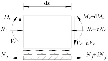
Based on the relationship between the force and the distribution force in the literature [16], differentiating Eq. (5), then put Eq. (3) into the formula after being differentiated, is:
Fig. 2Force diagram of micro-unit at interface
4. Deflection equations of simply supported beam reinforced with external prestressing and carbon fiber cloth
4.1. Displacement formulas of composite beam reinforced with external prestressing
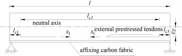
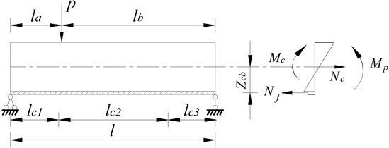
Composite beam reinforced with external prestressing can be considered as the internal statically indeterminate problem [17, 18] as shown in Fig. 3.
Fig. 3Simply supported beam after joint reinforcement
Axial force balance equation of composite beam, when external force is zero, is:
Force method equation can be got:
where is the relative displacement of prestressing tendons’ left and right sides at the location of min-span when 1, it is the constant displacement; is the relative displacement of prestressing tendons’ left and right sides at the location of min-span under external load, it is the load displacement.
4.2. Solution of constant displacement
According to equilibrium conditions of the internal and external bending moments:
According to Eq. (2) and Eq. (4):
Substituting Eqs. (3) and (6) into Eq. (7):
Substituting Eqs. (3) and (5) into Eq. (9):
According to Eqs. (6), (10) and (11):
Substituting Eq. (13) into Eq. (12):
where:
Solve the differential equations:
where ; , , , , , are undetermined coefficients.
Fig. 4Force diagram of simply supported beam
Substituting Eq. (15) into Eq. (13) when :
When :
When :
Integral Eq. (16) when :
When :
When :
Integral Eq. (17) when 0 :
When :
When :
Integral Eq. (15):
According to Eqs. (10), (17) and (19) when 0 :
When :
When :
According to the displacement continuous equations of composite beam and balance relation of axial force, boundary conditions can be got as follows:
Substituting Eqs. (15), (18), (19) and (20) into boundary conditions:
where:
The constant displacement can be got by the relative displacement of prestressing tendons’ left and right sides at the location of min-span:
Substituting Eqs. (17) and (20) into Eq. (22):
4.3. Solution of load displacement
The analytical solution of the deflection of composite beam under vertical loads is derived in literature [19]. Based on the situation in this paper, the deflection equation of beam under external force can be got when :
When :
where:
where:
Integral Eq. (24) when :
When :
According to the geometrical relation, the relative displacement of prestressing tendons’ left and right sides at min-span is:
Substituting Eq. (26) into Eq. (27):
4.4. Deflection equations of joint reinforcement beam
According to Eqs. (8), (23) and (28):
Then the deflection equations of simply supported beam reinforced with external prestressing and carbon fiber cloth can be got when 0 :
When :
When :
When :
5. Calculation of transverse distribution coefficients
5.1. Calculation of mid-span deflection
The mid-span deflection of simply supported composite beam can be got by Eq. (30), when :
where:
5.2. Calculation of transverse distribution coefficients
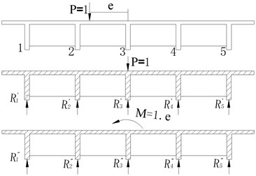
Get the crossbeam from the min-span as a free body and the force acting on the beam including the external loadand counter-force of each main girder. Because the stiffness of crossbeam at the min-span is infinite, the effect of eccentric load is equal to the sum of centric loads and .
According to the literature [20]:
1) Under centric load 1:
2) Under :
3) The total effect of eccentric load 1 to each main girder is:
Fig. 5Force diagram of each main girder under eccentric load
6. Example of reinforcement and analysis
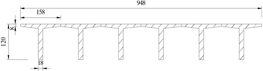
The analytical solution of the external prestressing and carbon fiber reinforced beam derived in this paper was verified by the ANSYS numerical simulation, and the integral forced performance of the strengthened bridge was studied by using the method of introduced transverse distribution coefficient. A simply supported beam shown in figure 6 was analyzed as the example. The standard span is 20 meters, when the flexural stiffness of main girder No. 1 was reduced by 20 % and the bending stiffness of other girders is normal, one layer of carbon fiber cloth was pasted on main girder No. 1, and externally prestressing tendons were tensioned.
Fig. 6Cross-section of T beam (cm)
The solid65 element was used in the ANSYS verification model to simulate the main beam, link8 element and shell41 element were used to simulate the external prestressed reinforcement and carbon fiber, and the bond slip between concrete and carbon fiber was simulated by establishing “contact pairs”. The model can actually reflect the stress condition of beam reinforced by external prestressing and carbon fiber as per the model shown in Fig. 7.
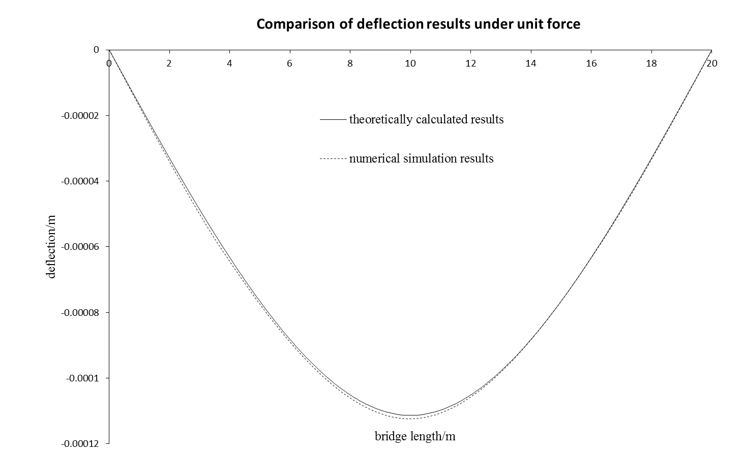
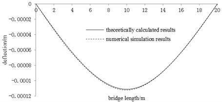
The deflection values obtained by the ANSYS analysis were compared with the results obtained by the analytical solution of deflection derived in this paper under unit force, as shown in Fig. 8. It can be seen from the comparison that the results of numerical simulation were in a good agreement with the results of theoretical calculation, and the maximum difference between mid-span deflections, which verified the correctness of the analytical solution of the deflection derived in this paper, is 1.2 %.
Fig. 7ANSYS theoretical verification model
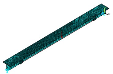
Fig. 8Comparison of deflection results under unit force
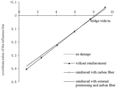
In order to analyze the improvement of bearing capacity of the whole bridge after reinforcement, the influence lines of transverse distribution to main girders should be calculated in the cases of no-damage, damage with reinforcement and without reinforcement respectively, and then the changes of transverse distribution coefficients should be analyzed. The influence lines of transverse distribution of No. 1 and No. 2 were calculated in each case, the results are shown in Fig. 9 and Fig. 10. Then the load transverse distribution coefficients of each main girder were calculated based on the results of influence lines of transverse distribution, as shown in Table 1.
Fig. 9Influence line of transverse distribution of main girder No.1
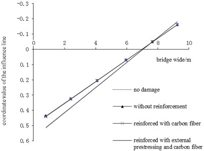
Fig. 10Influence line of transverse distribution of main girder No.2
In the bridge structure, the force distribution between the main girders is mainly related to their bending rigidities, the force is proportional to the flexural rigidity. When the bridge main girder is damaged, as its stiffness decreases, its shared force became lower. And the shared force of other main girders becomes higher, under the condition that the total load is constant. Thus, a chain reaction is produced, leading to a damage of other main girders, which seriously affects the bearing capacity of the bridge structure. Nevertheless, the bridge reinforcement can effectively improve the force distribution ratio of the main girder. In this paper, due to the researches of main girders’ transverse distribution coefficient, the following points are worth of attention.
1) Carbon fiber reinforcement can effectively inhibit the development of cracks, but the cracks cannot be closed. At the same time, the strength of carbon fiber is larger, what can improve the bearing capacity of the main girder after reinforcement. However, the cross-sectional area of carbon fiber is small, what has no obvious effect on the improvement of the stiffness of the main girder, there was no obvious change in the distribution of the force before reinforcement.
2) The external prestressing reinforcement can make the crack close and improve the flexural rigidity of the main girder, but the prestressing force is too large. For an old bridge with lower concrete strength, it is easy to cause the crack on the upper edge of the simple beam and produce a new damage.
3) According to Fig. 9 and Fig. 10, the load assigned to the main girder reinforced with external prestressing, and carbon fiber has grown because the stiffness of girder damage increases. As shown in this example, main girder No. 1 damaged with reinforcement which vertical coordinate values of influence line of transverse distribution at the location of the main girder No. 1 increased by 14.5 % as compared to the same without reinforcement; No. 2 main girder’s vertical coordinate values of influence line of transverse distribution at the location of main girder No. 1 reduced by 5.2 % than those without reinforcement. As shown in table 1, the transverse distribution coefficient of main girder No. 1 increased by 18.0 % than that without reinforcement. The difference of transverse distribution coefficients of damaged main girder No. 2 with and without reinforcement is merely 0.2 %. The joint reinforcement method can effectively improve the bearing capacity of the bridge up to the undamaged bridge.
Table 1Load transverse distribution coefficients of main girder in each case
Number of girder | No damage mc0 | Without reinforcement mc1 | Reinforced with carbon fiber mc2 | Reinforced with external prestressing and carbon fiber mc3 |
No. 1 | 0.598 | 0.503 | 0.507 | 0.593 |
No. 2 | 0.498 | 0.522 | 0.521 | 0.499 |
7. Conclusions
The analytical solution of the carbon fiber-concrete composite beams under the vertical concentrated load and external prestressing was derived in this article based on the elastic mechanics and contact theory, and the correctness of the analytical solution is verified by the ANSYS numerical simulation. It will provide an accurate calculation method for the design of beam structure strengthened with external prestressing and carbon fiber. On this basis, the transverse distribution coefficient calculation method of simply supported composite beam after the joint reinforcement was given. The transverse distributive regularity of beam reinforced with external prestressing and carbon fiber was analyzed through an example. Researches showed that: the deflection of beam strengthened with external prestressing and carbon fiber can be basically restored to the magnitude of deflection when the bridge is not damaged. With the increase of stiffness of damaged beam, the load sharing ratio will increase. And the reinforcement method can make the bearing capacity of the old bridge reach the level of the bridge without damage.
References
-
Wei Xing, Qiang Shi Zhong, GaoWei Usual method for reinforcing old bridge. Journal of High Way and Transportation Research and Development, Vol. 19, Issue 5, 2002, p. 85-87.
-
Grace N. F., Singh S. B. Durability evaluation of carbon fiber-reinforced polymer strengthened concrete beams. Experimental Study and Design, Vol. 102, Issue 1, 2005, p. 40-53.
-
Xu Li Hua, Xu Feng, Le Huang Calculation method for short-term deflection of concrete t-beam reinforced by externally prestressing with CFRP tendons. Engineering Mechanics, Vol. 1, 2015, p. 43-49.
-
Roberts T. M., Hajikazemi H. Theoretical study of the behaviour of reinforced concrete beams strengthened by externally bonded steel plates. Ice Proceedings, Vol. 87, Issue 1, 2015, p. 39-55.
-
Lu Wei, Liu Xing, Zhang Mi Mi Experiment and application study of bridge strengthened with cfrp sheets and external pre-stressed tendons. Journal of Hunan University of Science and Technology (Natural Science Edition), Vol. 22, Issue 4, 2007, p. 59-64.
-
Xu Wen Ping, Zong Hua, Zhang Yu Feng Study of structural properties of concrete t-beams strengthened by combined utilization of bond steel plates and external prestressing. World Bridges, Vol. 2, 2011, p. 69-72.
-
Lu Wei, Liu Xing, Li Yan Xian Experiment and simulation of structure strengthened with CFRP sheets and external pre-stressed tendons. Building Science, Vol. 24, Issue 3, 2008, p. 27-35.
-
Bolduc B., Matthew W. Usage of Carbon Fiber Reinforced Polymer Plates for Repair Or Retrofit of Pre-Stressed and Reinforced Concrete Girders. University of Cincinnati, Ohio, USA, 2003.
-
Choi Jungyoul Comparative study of effective stresses of concrete beams strengthened using carbon-fiber-reinforced polymer and external prestressing tendons. Structure and Infrastructure Engineering, Vol. 10, Issue 6, 2014, p. 753-766.
-
Han M. Y., Yoo H. S., Park S. K. Strengthening method of PSC girder using external prestressing and glass fiber reinforcement. Proceedings of the Korean Civil Society, Vol. 19, Issue 19, 1999, p. 1-3.
-
Ghallab A., Beeby A. W. Calculating stress of external prestressing tendons. Proceedings of the Institution of Civil Engineers Structures and Buildings, Vol. 157, Issue 4, 2004, p. 263-278.
-
Yu Tian Li Mechanical Behavior Research of Concrete Beam Strengthened with CFRP Sheets. Northeast Forestry University, Harbin, 2005.
-
Guo Zhen Hai Experimental Research on Mechanical Performance and Design Method of RC Composite Beam. Tsinghua University, Beijing, 1965.
-
Nie Jian Guo Steel and Concrete Composite Beams Structure. Science Press, Beijing, 2005.
-
Jian Li Zhong, Xu Zhi Wu, Li Jia Theoretical analysis of slip and deformation of steel concrete composite beam under uniformly distributed loads. Engineering Mechanics, Vol. 20, Issue 2, 2003, p. 133-137.
-
Nie Jian Guo, Shen Ju Min, Yuan Yan Sheng General formula for predicting the deflection of simply supported composite steel-concrete beams. Engineering Mechanics, Vol. 11, Issue 1, 1994, p. 21-27.
-
Dall'asta Andrea, Ragni Laura, Zona Lessandro A. Simplified method for failure analysis of concrete beams pre-stressed with external tendons. Journal of Structural Engineering, Vol. 133, Issue 1, 2007, p. 121-131.
-
Xiong Xue Yu, Wang Shou Sheng Deflection calculation of externally prestressed concrete beam. Industrial Construction, Vol. 34, Issue 7, 2004, p. 12-15.
-
Liu Han Bing, Ma Hui, Liu Tian Ming, Zhang Yun Long Analytical solution of steel-concrete composite beam under vertical loads. China Journal of Highway and Transport, Vol. 23, Issue 4, 2010, p. 39-44.
-
Fan Li Chu Bridge Engineering, China Communications Press, Beijing, 2001.
About this article

