Abstract
An admissible function constructed by orthogonal polynomials is presented to investigate the vibration and active flutter control of Honeycomb sandwich plate with general elastic support in a supersonic airflow. The control strategies based on the displacement feedback and LQR method are applied by means of pasting the piezoelectric material on the surface of the plate structure. Employing the first-order piston theory to describe the aerodynamic loads, the governing equation of plate system with the piezoelectric actuator is established based on the Hamilton principle. The mode shapes are obtained using the admissible functions, which are a set of characteristic orthogonal polynomials generated directly by employing the Gram-Schmidt process, and the general elastic constraint is modeled using the artificial spring technology. The frequency and mode shape under different boundary are calculated by Rayleigh-Ritz method. The validity of the proposed approach is confirmed by comparing the results with those obtained from FEM and literatures. The phenomenon of mode jumping is observed with the increase of the aerodynamic pressure. The study of active control shows that, the increasement of displacement feedback gain improves the critical dynamic pressure.
1. Introduction
For the construction and design of the lightweight systems, the weight saving is one of the major considerations. A kind of sandwich structure is often used to meet this requirement. Nowadays, thermal protection mechanism of reusable launch vehicles, solar housing, shrouds of spacecraft are in extensive use of honeycomb sandwich structures. Honeycomb sandwich plate is composed of two layers of strong, thin face sheets and a layer of thick but light honeycomb core. Generally, honeycomb core acts as a connecting and supports the face sheets [1]. In the engineering area, there are three equivalent models for mechanical analysis of sandwich structures. For the hexagonal honeycomb plate, these methods are divided into the sandwich theory, cellular equivalent plate theory and equivalent plate theory. The first method is only used to get an equivalent anisotropic plate of the honeycomb core, and the others are adopted to obtain an equivalent plate for the whole honeycomb sandwich plate [2, 3]. By using the three equivalent methods, the natural frequencies of a honeycomb sandwich panel including two load cases were calculated by Xia [3]. The computational results showed that all of the three equivalent methods were reliable and practical in the satellite structures. Paik [1] constructed an isotropic plate using the equivalent plate theory, subjected to a tensile, bending and torsion tests. It was found that the experiment results of honeycomb sandwich plate were close to the equivalent plate. Surveying the open literatures, the problems from the aspects of mechanical analysis of the honeycomb sandwich plate have been resolved [4, 5], however the aeroelastic analysis is rarely carried out. Moreover, the research on the vibration and flutter problem of the plate structure with general elastic support is rarely found.
Currently, the calculations for the flutter problems mainly include the Galerkin method and finite element method [6, 7], which are used to disperse the partial differential equations into a set of ordinary differential equations. Due to the fact that there are no exact modal functions for the general elastic boundary structure, the scholars focus on the flutter analysis of structure with simply supported boundary. For the problem that how to realize the general elastic support, some scholars have discussed the frequency characteristics of simple structures. Amabili [8] used the artificial springs to study the vibration problems of cylindrical shells with complex boundary constraints, where the modes in the less-restrained condition were applied to expand the solutions of displacement. The free vibration of composite laminated shells under elastic boundary was studied by Jin [9] using Rayleigh-Ritz procedure, in which the displacements were expressed by a Fourier cosine series and the effects of boundary restraining stiffness on the frequency were illustrated. Mahi [10] investigated the free vibration problem of the composite panels with different boundaries, employing a series of polynomials associated with the Rayleigh-Ritz method. Ye [11] discussed the free vibration of laminated composite shallow shells with general elastic boundaries. Zhang [12] proposed a method to solve the vibration problem of plates under the elastic edge restraints, where the rotational and translational restraints were applied to an edge. Lin [13, 14] presented an admissible function to investigate the vibration and flutter problem of laminated plate and FGM cylindrical shells with arbitrary boundaries. However, the frequency and modes under elastic support are rarely used to solve the complicated problem, such as the flutter, response and control problem. Due to the fact that a large number of Fourier cosine series, polynomials or other forms are required based on the admissible function, which makes the expression of the mode function complicated.
The active control study on the vibration and flutter of plate and shell structures never stops, especially when the smart materials and piezoelectric materials have been widely used. Hajela [15] implanted piezoelectric material inside a composite plate to study the plate flutter problem using the finite element method. Balamurugan [16] employed different active control methods to investigate the dynamics problems of structure based on the distributed piezoelectric actuators and sensors, which were embedded on the upper and lower surfaces of structure. Li [17] designed the displacement and acceleration feedback control algorithms, to realize active flutter control of panel structure using the piezoelectric material. Kim [18] used the aeroelastic modes and self-induced actuators to control the panel flutter, and the location configuration based on the position feedback gain control and the Kalman filter gain method were optimized. Song [19] investigated active aeroelastic flutter control of supersonic composite laminated plate with the piezoelectric patches.
In this paper, a general classical plate theory in conjunction with Gram-Schmidt polynomials and Rayleigh-Ritz procedure is developed, where each displacement component of the plate structure is expanded as orthogonal polynomials form in both directions. The solution procedure of active flutter control is divided into two steps, first obtaining the frequency and mode of the plate based on the Rayleigh-Ritz method, in which the boundary support is formulated by the artificial spring. The different boundary conditions can be realized by setting the stiffness value of artificial springs to be extremely large, small or arbitrary. The equivalent plate theory is adopted to facilitate the honeycomb sandwich plate. Then, the mode shapes and generalized coordinates are taken into the Hamilton equation to derive the governing equations of the plate system. A convergence analysis of the polynomials number on the natural frequency is carried out. The proposed approach is proved by comparing the frequency and flutter pressure with FEM and literatures. The active control strategy based on the displacement feedback gain and LQR method are applied using the piezoelectric material. The effects of displacement feedback gain on the critical dynamic pressure and response are highlighted.
2. Theoretical formulation
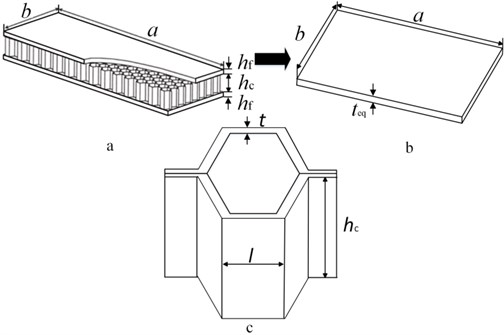
The typical honeycomb sandwich plate is composed of two face sheets and a honeycomb core, shown in Fig. 1. The Honeycomb core and face sheet materials are aluminum, , and are elastic modulus, shear modulus and density, respectively. The length and width of the honeycomb sandwich plate are and . The core, face sheet and the entire honeycomb sandwich plate thickness are , and , respectively. And and are a unit cell size and the thickness of the honeycomb core. Index and represent the core and the face sheet.
Fig. 1a) Honeycomb sandwich plate, b) equivalent plate structure, c) honeycomb core
2.1. The equivalent model of honeycomb sandwich plate
Generally, there are three equivalent models for mechanical analysis of the honeycomb sandwich structures, the sandwich theory, cellular equivalent plate theory and equivalent plate theory. The validity of the equivalent plate theory is verified by Paik tests [1], which gives the elasticity modulus and thickness of plate according to the equal principle of stiffness and density, ultimately making the honeycomb sandwich plate equivalent to an isotropic plate. Supposing the sheet satisfies Kirchhoff hypothesis, the equation can be obtained according to the equivalent bending stiffness:
where, , are the equivalent elastic modulus and thickness of the plate, is Poisson ratio. Using the equivalent principle between the equivalent plate and honeycomb sandwich plate, the equation can be written as:
The equivalent plate parameters are finally obtained based on Reissner theory [2]:
where, is the average mass density of honeycomb core, .
A FEM model is set up to solve the honeycomb sandwich plate problem adopting the sandwich theory (ANSYS Shell 91), where the core is equivalent to the orthotropic material, and the face sheet is treated as the isotropic material. The material parameters of core layer are determined by means of model using the energy method:
where, () is the elastic modulus of honeycomb core, , and are the shear modulus of honeycomb core, is the density of the honeycomb core. The FEM result using the sandwich theory is regarded as the reference value.
2.2. Constitutive relation of equivalent sandwich plate and piezoelectric material
The equivalent plate structure with the piezoelectric layer in a supersonic airflow, is shown in Fig. 2. The length, width and thickness of the plate are , and respectively, the airflow is along the x axis direction. The artificial springs are distributed on the edges of plate to model the elastic support conditions. The different boundaries can be obtained by accordingly setting the artificial spring stiffness to be extremely large, small or arbitrary value.
Fig. 2Equivalent plate with the piezoelectric layer under general elastic support
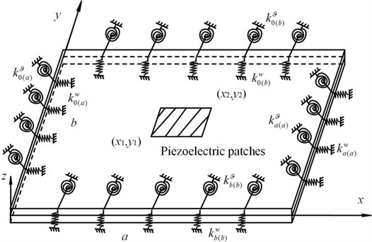
The piezoelectric actuator is pasted on the upper surface of plate, the position coordinates are and . The plane displacements , and transverse displacement of the plate are expressed as:
where, is the coordinate of any point along the -axis direction. The strain-displacement relation is written as:
where, , and are the strains in , direction and shear strain in - plane, respectively. The constitutive relation of the plate structure is:
where, , and are the stress in , direction and shear stress in - plane, respectively. , , . The constitutive relation of piezoelectric layer is expressed as:
where, , and are the stress of piezoelectric material in the , direction and shear stress in - plane, respectively. , and are the piezoelectric constants, dielectric constant and electric displacement, respectively. is the electric field strength in the direction:
where, is the thickness of the piezoelectric layer, is the applied voltage.
The total kinetic energy of the plate system with the piezoelectric layer is calculated as:
where, and is the volume of the plate and piezoelectric layer, is the density of piezoelectric material.
The total potential energy of the plate system with the piezoelectric layer is calculated as:
where, and are the strain vector and stress vector of plate structure, and are the strain vector and stress vector of piezoelectric layer.
2.3. The simulation of general elastic support boundary
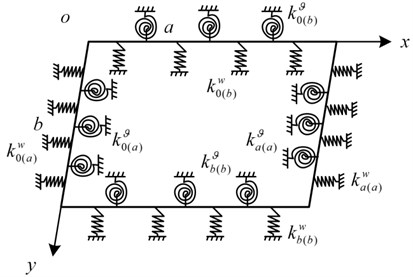
The artificial springs are used to describe the connection between the plate and the support members. The springs are evenly distributed on the edges of the plate, and the elastic supports adopt the tension spring and torsion spring, where the corresponding stiffness are and , shown in Fig. 3. The key of the remaining problem is to find the admissible functions to expand the displacement components of the plate structure, which are introduced in Part 2.4.
Since the artificial springs have no mass, only the potential energy is calculated as:
where, , , , and , , , are the stiffness of the tension spring and torsion spring at 0 and , 0 and , respectively.
Fig. 3Elastic support plate with a set of artificial springs
2.4. Method of solution
The Rayleigh-Ritz method is used to obtain the frequency and mode functions. The transverse displacement can be expressed as:
where, is the circular frequency, is mode shape which can be determined by Gram-Schmidt orthogonal polynomials, i.e.:
where, is the unknown coefficient, and are the orthogonal polynomials in the and directions, respectively. and are the truncation number of polynomials.
Substituting Eqs. (5-7) into Eq. (12), only the potential energy of plate structure is considered:
where, , .
Substituting Eqs. (14, 15) into Eqs. (11, 13, 16), the Rayleigh quotient to corresponding factors is written as:
The minimizing condition with energy function yields the generalized eigenvalue problem:
where, and are matrices, . The matrices , and are determined as:
where, is the stiffness matrix of vibratory stress, is the stiffness matrix of the artificial springs, , , , .
The construction of Gram-Schmidt orthogonal polynomials is as follows, giving the first term of orthogonal polynomial cluster , which satisfies the certain boundary condition. According to the steps of orthogonal polynomial cluster configuration, the remaining items can be calculated as:
where, ,
Each polynomial is normalized as:
If the first term satisfies the geometry boundary conditions, it is easy to verify that other terms do. The relationship between any two orthogonal polynomials is:
The first item of polynomials with different boundary conditions is shown in Table 1. The letter, F represents for freedom, C for clamped, S for simply supported.
Table 1First term of the polynomial for different boundary conditions along x direction
Boundary | Constraint | First term |
F-F | ||
C-F | ||
S-S | ||
C-C | ||
S-F | ||
C-S |
2.5. The governing equations
Using the mode function in Part 2.4 to derive the governing equation based on the assumed mode method, the displacement of the plate is written as the following form:
where, is the generalized coordinate, is the corresponding mode function obtained from the Rayleigh-Ritz approach, and are the modal order, and:
Substituting Eq. (26) into Eqs. (11-12), the expressions of potential energy and kinetic energy can be obtained:
where:
The potential energy of the plate system with the piezoelectric layer is expressed as:
where:
The aerodynamic pressure caused by the supersonic flow can be described by the quasi-steady-order piston theory, which has a good accuracy in the Mach number , the expression can be written [17, 20]:
where, , are the aerodynamic stiffness and aerodynamic damping coefficient, respectively. , and are the free flow density, flow velocity and Mach number.
The virtual work can be expressed as:
where, is the external force, is the aerodynamic load, is the plate area, and is the damping coefficient, , are the damping and aerodynamic stiffness matrix, respectively:
The governing equations of the plate system is established based on Hamilton principle:
where, , and are the virtual work of the kinetic energy, strain energy and external loads. Substituting Eqs. (27-28) and Eq. (30) into Eq. (31), the final motion equation is:
where, , and are modal mass matrix, stiffness matrix and electro-mechanical coupling matrix, respectively.
3. Active control strategy
3.1. Flutter control based on the displacement feedback method
The piezoelectric material can be used to design sensors and actuators [17]. In this paper, a voltage is applied on the piezoelectric material attached to the surface of the structures, which is designed to the piezoelectric actuator. The centre position displacement of plate is designed as an input, and the voltage value is calculated by the control strategy. The control voltage of the actuator based on the center position displacement can be written as:
where, is a piezoelectric actuator feedback control gain, is the center position displacement of the plate structure.
Substituting Eq. (26) into Eq. (33):
Substituting Eq. (34) into Eq. (32), the control equation can be obtained:
where, .
3.2. Flutter control based on the LQR method
The LQR method is adopted to control the flutter problem of plate structure, the governing equation is converted into the form of state space:
where is the state vector. The LQR algorithm is regarded as a feedback control, making the objective function to obtain the minimum value, and the objective function is usually proportional to the system response. The objective function is defined as:
where, and are positive definite and semi-definite matrix, which represent a measure of the effect of input and output on the control result. The feedback voltage can be determined:
where, is a feedback gain, can be calculated from the Riccati equation:
For the LQR control algorithm, the Lyapunov function of the system is defined as:
First derivative of time on Eq. (40), the equation can be written as:
It is noted that the Lyapunov function of the system is negative, the system is asymptotically stable, and the critical flutter point can disappear.
4. The solution of motion equation
Substituting the vibration displacement of plate, into Eq. (35):
The condition of Eq. (42) having nonzero solution is:
Then, the complex eigenvalues are obtained:
where, the frequency and damping ratio of the structure are calculated:
The flutter is a kind of dynamic instability phenomenon. The critical dynamic pressure is a state parameter between convergence and instability, write . The non-dimensional dynamic pressure can be defined as [21]:
One can find out the critical dynamic pressure by inspecting the maximal real part of eigenvalues. Moreover, it is found without considering the damping, the critical dynamic pressure coincides with the pressure when two consecutive low-level frequencies are equal. In this paper, the frequency coincidence theory is as the basis for the occurrence of flutter.
5. Numerical results
The material parameters and geometric parameters of Honeycomb sandwich plate and the piezoelectric layer are shown in Table 2 and Table 3. The length and width of plate structure are 0.8 m, 0.6 m, respectively.
Table 2The geometric and material parameters of the Honeycomb sandwich plate
Property | Face sheet | Honeycomb core |
(N/m2) | 72×109 | 72×109 |
(Kg/m3) | 2700 | 2700 |
(mm) | 0.8 | – |
(mm) | – | 8.5 |
(mm) | – | 4 |
(mm) | – | 0.05 |
Table 3Parameters of the piezoelectric material
Property | Piezoelectric material | Property | Piezoelectric layer |
(N/m2) | 139×109 | Width (m) | 0.1 |
(N/m2) | 77.8×10⁹ | Length (m) | 0.15 |
(N/m2) | 30.6×10⁹ | Thickness (mm) | 0.2 |
Density (Kg/m3) | 7600 | Dielectric constant (F/m) | 1.5×10⁻⁸ |
Stress constant (Vm/N) | 0.01 | Piezoelectric constant (C/m2) | –6.98 |
5.1. Convergence analysis
To validate the proposed method, the results for the simply supported isotropic base plate are compared with the analytical solution in Table 4, in which the bending stiffness of the base plate is . It is observed that the present results agree well with the analytical solution, where the number of Gram-Schmidt orthogonal polynomials is 8 in both and directions. Moreover, the first three mode shapes between FEM and present method are shown in Fig. 4.
Table 4A comparison between the analytical solution ω=π22πia2+jb2Dρh, (i, j= 1,2,3,…) and the present method (a= 0.8 m, b= 0.6 m, h= 0.02 m, E= 72×109 N/m2, ρ= 2700 Kg/m3, v= 0.3) / Hz
Order | Analytical solution | Present method | FEM |
1 | 213.08 | 213.08 | 212.91 |
2 | 443.20 | 443.20 | 442.58 |
3 | 622.19 | 622.19 | 621.17 |
4 | 826.75 | 826.78 | 825.30 |
Then, a clamped plate is taken as a numerical example to demonstrate the effect of the number of polynomials on the plate frequency. The parameters of Eq. (4) are calculated in the FEM model adopting the sandwich theory, and the model is shown in Fig. 5. From the comparison between the FEM and present method in Fig. 6 and Table 5, where an error variable is defined as when three or four-numbers polynomials are selected in and direction, the first two frequencies are close to the FEM results, however there is a big error for the high-order frequency. Moreover, with the increase of the number of orthogonal polynomials, the error for the high-order frequency is reduced. The frequencies of plate structure with different spring stiffness are given in Table 6. As the stiffness value of the tension and torsion springs are 108 N/m and 108 N·m/rad respectively, the frequency will coincide with the result of the fixed plate, which indicates that the fixed boundary can be obtained by setting an enough large spring stiffness value. Moreover, the frequencies under elastic support agree well with the FEM results, which guarantees the validity of the proposed method and the following flutter calculation.
Fig. 4The mode shapes of plate structure between FEM and present method
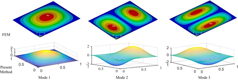
Fig. 5FEM model of plate based on the sandwich theory
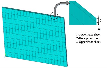
Fig. 6Convergence analysis
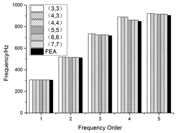
Table 5Convergence analysis with different orthogonal polynomials / Hz
Order | Number of orthogonal polynomials () | FEM | |||||||
3 | 4 | 5 | 6 | ||||||
Present | Error | Present | Error | Present | Error | Present | Error | ||
1 | 305.44 | 0.006 | 305.44 | 0.006 | 305.47 | 0.003 | 305.47 | 0.003 | 305.46 |
2 | 515.66 | 0.618 | 512.65 | 0.031 | 512.62 | 0.025 | 512.50 | 0.038 | 512.49 |
3 | 729.21 | 1.352 | 719.06 | 0.058 | 718.94 | 0.075 | 719.12 | 0.050 | 719.48 |
4 | 883.69 | 3.555 | 883.69 | 3.555 | 854.45 | 0.129 | 853.37 | 0.125 | 853.35 |
Table 6The frequency of the plate with different spring stiffness /Hz (a= 0.5 m, b= 0.4 m, h= 0.002 m)
Order | The stiffness of the artificial spring , | Fixed | |||||
1e8 | 1e3 | 0 | |||||
FEM | Present | FEM | Present | FEM | Present | FEM | |
1 | 91.36 | 91.53 | 19.20 | 19.99 | 33.01 | 32.97 | 91.36 |
2 | 159.71 | 160.70 | 29.62 | 31.05 | 41.67 | 41.66 | 159.71 |
3 | 210.05 | 209.57 | 38.56 | 39.07 | 68.73 | 68.64 | 210.05 |
4 | 270.63 | 273.02 | 55.67 | 56.78 | 79.62 | 79.37 | 270.63 |
5.2. Vibration characteristics of plate under general elastic boundary
The proposed method in this paper can be used to simulate all the classical boundaries by setting the artificial spring stiffness value. A comparative analysis for the plate under several classical boundaries is shown in Table 7. It can be noted that the results using the artificial spring technology agree well with the FEM results. The natural frequencies of the plate with/without the piezoelectric actuators are listed in Table 8. The addition of piezoelectric layer cannot significantly change the intrinsic property of the base plate structure, which is what we must achieve. Because the active vibration and flutter control are mainly realized by applying control algorithm, instead of just pasting the piezoelectric layer.
Table 7Frequency of the plate base under classical boundary conditions / Hz
Order | CFFF | SSSS | CSCS | |||
FEM | Present | FEM | Present | FEM | Present | |
1 | 21 | 21 | 164 | 164 | 210 | 210 |
2 | 62 | 62 | 341 | 341 | 452 | 452 |
3 | 128 | 128 | 478 | 479 | 502 | 503 |
4 | 216 | 215 | 636 | 637 | 731 | 734 |
5 | 261 | 261 | 654 | 656 | 811 | 811 |
6 | 365 | 364 | 947 | 951 | 1016 | 1019 |
Order | CCSS | CFCF | CCFF | |||
FEM | Present | FEM | Present | FEM | Present | |
1 | 227 | 227 | 132 | 132 | 57 | 57 |
2 | 420 | 421 | 173 | 173 | 166 | 166 |
3 | 591 | 592 | 360 | 360 | 252 | 252 |
4 | 739 | 740 | 365 | 364 | 384 | 383 |
5 | 773 | 776 | 426 | 425 | 404 | 404 |
6 | 1079 | 1082 | 635 | 635 | 631 | 631 |
Table 8Frequency of plate system with/without piezoelectric layer / Hz
Order | CFCF | SSSS | CCCC | |||
Without | With | Without | With | Without | With | |
1 | 132 | 132 | 164 | 165 | 305 | 305 |
2 | 173 | 173 | 341 | 343 | 512 | 512 |
3 | 360 | 364 | 478 | 481 | 719 | 719 |
4 | 365 | 366 | 636 | 640 | 853 | 853 |
5 | 426 | 426 | 654 | 659 | 909 | 909 |
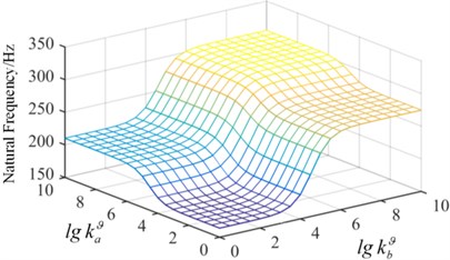
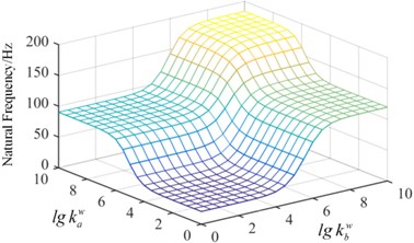
Fig. 7Surface graph of the relationship between the frequency and spring stiffness
a) The first mode
b) The second mode
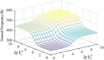
In order to demonstrate the effect of spring stiffness on the natural frequency, in Condition-1, the tension spring value of is fixed, 109 N/m and the torsion spring stiffness continuously changes from a small value to a big value, which realizes the change from the simple supported boundary to the clamped boundary, shown in Fig. 7. It is observed that when the spring stiffness value is 108, the natural frequency of the plate converges to a fixed value, which is the frequency of the clamped plate. The torsion spring in the x direction has a more significant impact on the fundamental frequency. In Condition-2, the value of is fixed as 109 (N·m)/rad in Fig. 8. As the stiffness of the artificial spring is bigger than 108 N/m, the frequency of plate structure does not change with the increase of the spring stiffness. It can be concluded that the springs stiffness has a significant effect on the inherent properties of the plate structure, and the arbitrary boundary can be obtained by setting different stiffness value of artificial springs.
Fig. 8Surface graph of the relationship between the frequency and spring stiffness
a) The first mode
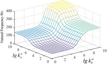
b) The second mode
5.3. Flutter and control analysis of honeycomb sandwich plate
The plate structures investigated by Zhao [22] and Li [17] are adopted to compare the critical flutter pressure with the present results, shown in Table 9. It is observed that the present results agree well with the open literatures, which indicates that the proposed method and formula derivation for flutter calculation are valid.
Table 9Critical dynamic pressure of the plate structures
Property | Literature | This paper |
Critical flutter pressure | Li [17] 26.97 | Present 27.01 |
Zhao [22] 235.18 | Present 236.20 |
The simply supported and clamped plates are taken as examples to investigate the active flutter control problem. In Fig. 9, the third and fourth order frequencies of the simply supported plate coincide in 230 with the increase of dynamic pressure, then the coincidence between the second and fourth frequencies leads to flutter instability of the plate system in 237. The mode jumping phenomenon appears in 230. In order to better display the phenomenon, the mode shapes in 220 and 240 considering the aerodynamic loads are shown in Fig. 10. It is observed that the third mode and the fourth mode interchanges. Under the action of the aerodynamic loads, the mode shapes of the plate structure have significantly changed.
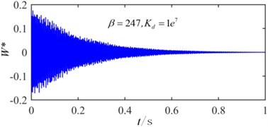
The critical flutter boundaries of the plate system with/without active control input based on the displacement feedback method are shown in Fig. 11 and Fig. 12 for the simple supported and clamped plates, respectively. It is noted that with the increasing of the feedback gain, the critical dynamic pressure is improved, and a good control effect has been achieved setting different feedback gain. Moreover, the bigger the feedback gain is, the higher the critical dynamic pressure becomes. The critical dynamic pressure of the clamped plate is obviously higher than that of the simply supported plate, which indicates that increasing the boundary constraint stiffness can improve the aerodynamic stability of the system. The time history with/without the displacement feedback control in 247 are shown in Fig. 13 and Fig. 14, in which the non-dimensional displacement , is the transverse displacement of the plate. Without the active control, the plate displacement continues to increase, and a divergence response occurs. After applying the active control, the divergence motion becomes a convergence vibration, and the plate response is suppressed. The time history under different control feedback gain is shown in Fig. 15, it is observed that the bigger the feedback gain is, the smaller the response amplitude is, and the better results the active control can get.
Fig. 9Frequency of the simply supported plate
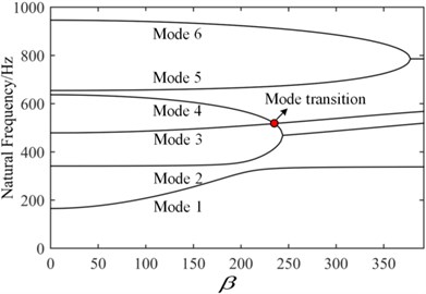
Fig. 10Mode jumping phenomenon
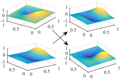
Fig. 11Flutter boundary of the simply supported plate
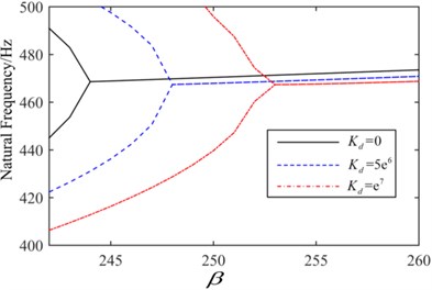
Fig. 12Flutter boundary of the clamped plate
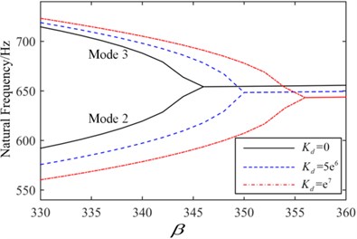
Fig. 13Time history when β= 247 without control
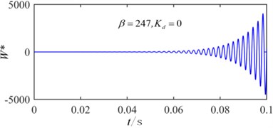
Fig. 14Time history when β= 247 with active control
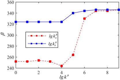
The critical flutter boundary with different spring stiffness is shown in Fig. 16. With the increasing of the spring stiffness ( 109 N·m/rad), the coincidence frequencies change from the coupling between the third and fourth mode to the coupling of the second and the fourth mode. Moreover, the mode jumping phenomenon occurs with increasing of the dynamic pressure. The critical flutter pressure can be improved by appropriately increasing the elastic support stiffness. The effect of torsion springs stiffness on the critical dynamic pressure is shown in Fig. 17, here 109 N/m. It is noted that with the increasing of torsion spring stiffness, the critical dynamic pressure is improved and eventually converges to a fixed value, which is the dynamic pressure of the clamped plate. When 103 (rad·m)/rad or 107 (rad·m)/rad, the critical dynamic pressure is almost a constant.
Fig. 15Time history under a different displacement feedback gain
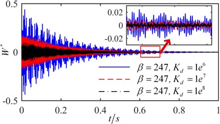
Fig. 16Flutter boundary of the plate with a different spring stiffness
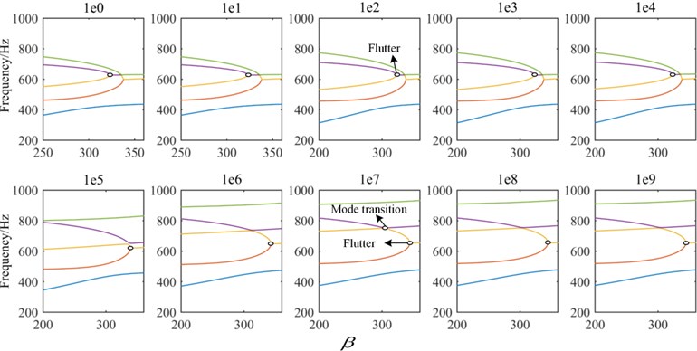
Fig. 17Flutter boundary of plate under the elastic support boundary (kw= 109 N/m)
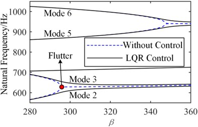
The flutter boundaries of the system with/without active control input based on the LQR method are shown in Fig. 18 and Fig. 19 for the simple support plate and elastic support plate, respectively. As the dynamic pressure is further increased after applying the LQR control strategy, the original coincidence frequencies expand backward indefinitely, and there is not an intersection, which indicates that the flutter is suppressed. The same phenomenon occurs for the elastic support plate in Fig. 19. It can be concluded that the LQR control method can eliminate the flutter point rather than just improving the critical dynamic pressure.
Fig. 18LQR control of simply support plate
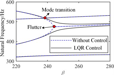
Fig. 19LQR control of elastic support plate (kw=kϑ= 108)
6. Conclusions
A unified Gram-Schmidt-Ritz formulation is proposed to solve the vibration and active flutter control problem of Honeycomb sandwich plate with general elastic support boundary. The effects of artificial spring stiffness and different boundary on the dynamic behaviors of the plate structure are discussed. Multiple new phenomena and conclusions can be drawn:
1) The proposed method using an admissible function constructed by Gram-Schmidt orthogonal polynomials to investigate the vibration problems of the elastic support plate, has sufficient accuracy. Moreover, with the number of orthogonal polynomials increasing, the precision of results will be improved.
2) The artificial spring stiffness can significantly affect the vibration characteristics of the structure, which results in the change of critical flutter boundary. A large stiffness of the support spring is helpful to improve the aerodynamic flutter boundary of plate structure.
3) With the increasing of the aerodynamic pressure, the phenomena of mode jumping and the alterations of coupled mode orders are observed. The study of active control shows that, an increase of the displacement feedback gain can improve the critical dynamic pressure. The LQR control strategy can eliminate the flutter point.
References
-
Paik J. K., Thayamballi A. K., Kim G. S. The strength characteristics of aluminum honeycomb sandwich panels. Steel Construction, Vol. 35, Issue 3, 1999, p. 205-231.
-
Liu J., Zhou C. Y. Influence of length-thickness ratio on dynamic calculation accuracy of equivalent plate model of hexagonal aluminum honeycomb sandwich plate. Acta Materiae Compositae Sinica, Vol. 33, Issue 8, 2016, p. 1838-1847.
-
Xia L. K., Jin X. K., Wang Y. B. Equivalent analysis of honeycomb sandwich plates for satellite structure. Journal of Shanghai Jiaotong University, Vol. 37, Issue 7, 2003, p. 999-1001.
-
Zhang J., Ashby M. F. Buckling of honeycombs under in-plane biaxial stresses. International Journal of Mechanical Sciences, Vol. 34, Issue 6, 1992, p. 491-509.
-
Yeh W. N., Wu Y. E. Enhancement of buckling characteristics for sandwich structure with fiber reinforced composite skins and core made of aluminum honeycomb and polyurethane foam. Theoretical and Applied Fracture Mechanics, Vol. 15, Issue 1, 1991, p. 63-74.
-
Raja S., Pashilkar A. A., Sreedeep R., Kamesh J. V. Flutter control of a composite plate with piezoelectric multilayered actuators. Aerospace Science and Technology, Vol. 10, Issue 5, 2006, p. 435-441.
-
Navazi H. M., Haddadpour H. Aero-thermoelastic stability of functionally graded plates. Composite Structures, Vol. 80, Issue 4, 2007, p. 580-587.
-
Amabili M., Garziera R. Vibrations of circular cylindrical shells with nonuniform constraints, elastic bed and added mass. Part I: empty and fluid-filled shells. Journal of Fluids and Structures, Vol. 14, Issue 5, 2000, p. 669-690.
-
Jin G., Ye T., Chen Y., Su Z., Yan Y. An exact solution for the free vibration analysis of laminated composite cylindrical shells with general elastic boundary conditions. Composite Structures, Vol. 106, Issue 12, 2013, p. 114-127.
-
Mahi A., Bedia E. A. A., Tounsi A. A new hyperbolic shear deformation theory for bending and free vibration analysis of isotropic, functionally graded, sandwich and laminated composite plates. Applied Mathematical Modelling, Vol. 39, Issue 9, 2014, p. 2489-2508.
-
Ye T., Jin G., Chen Y., Ma X., Su Z. Free vibration analysis of laminated composite shallow shells with general elastic boundaries. Composite Structures, Vol. 106, 2013, p. 470-490.
-
Zhang X., Li W. L. Vibrations of rectangular plates with arbitrary non-uniform elastic edge restraints. Journal of Sound and Vibration, Vol. 326, Issues 1-2, 2009, p. 221-234.
-
Lin H., Cao D. Q., Xu Y. Q. Vibration characteristics and flutter analysis of a composite laminated plate with a store. Applied Mathematics and Mechanics, Vol. 39, 2018, p. 241-260.
-
Lin H., Cao D. Q., Shao C. H. An admissible function for vibration and flutter studies of FG cylindrical shells with arbitrary edge conditions using characteristic orthogonal polynomials. Composite Structures, Vol. 183, 2018, p. 748-763.
-
Hajela P., Glowasky R. Application of piezoelectric elements in supersonic panel flutter suppression. Aircraft Design and Operations Meeting, 2013.
-
Balamurugan V., Narayanan S. Shell finite element for smart piezoelectric composite plate/shell structures and its application to the study of active vibration control. Finite Elements in Analysis and Design, Vol. 37, Issue 9, 2001, p. 713-738.
-
Li F. M. Active aeroelastic flutter suppression of a supersonic plate with piezoelectric material. International Journal of Engineering Science, Vol. 51, Issue 2, 2012, p. 190-203.
-
Kim M., Li Q., Huang J. K. Active control of nonlinear panel flutter using aeroelastic modes and piezoelectric actuators. AIAA Journal, Vol. 46, Issue 3, 2008, p. 733-743.
-
Song Z. G., Li F. M. Active aeroelastic flutter analysis and vibration control of supersonic composite laminated plate. Composite Structures, Vol. 94, 2012, p. 702-713.
-
Ibrahim H. H., Hong H. Y., Lee K. S. Supersonic flutter of functionally grated panels subject to acoustic and thermal loads. Journal of Aircraft, Vol. 46, Issue 2, 2015, p. 593-600.
-
Koo K. N., Hwang W. S. Effects of hysteretic and aerodynamic damping on supersonic panel flutter of composite plates. Journal of Sound and Vibration, Vol. 273, Issue 3, 2004, p. 569-583.
-
Zhao H., Cao D. A study on the aero-elastic flutter of stiffened laminated composite panel in the supersonic flow. Journal of Sound and Vibration, Vol. 332, Issue 19, 2013, p. 4668-4679.
About this article

This work is supported by the National Natural Science Foundation of China (Grant No. 11472089).
