Abstract
In order to assess the vibration localization influences of different parameters of structural of the mistuned bladed disk system, the pre-stressed component mode synthesis method was adopted, and reduced-order models (ROMs) of the aero-engine compressor bladed disk system were built. Identification of the mistuning parameter was set based on the combination of blade static frequency, dichotomy and finite element analysis method. By Defining the vibration localization factor, the influence parameters such as the engine orders of excitation, mean frequency and stiffness ratio were considered, localization characteristics of the vibration response was analyzed, and the influence rule of different parameters on the vibration response were discussed. The result shows that the engine orders of excitation has significant influences on the frequency, displacement and strain energy distribution, with the increase of the engine orders of excitation, the relative localization factors firstly increase, and then decrease; the relative localization characteristics of the bladed disk system on the different mean frequencies were found out; with the increase of the stiffness ratio of the blade and disk, maximum vibration amplitude and strain energy of the bladed disk system gradually decline.
1. Introduction
The aero-engine compressor bladed disk system should be a circumferential cyclic symmetry structure in theory, however, due to the variance of manufacture, assembling, wear and chatter suppression, the difference on quality, stiffness and natural frequency between the blades were caused, that was called mistuning. Mistuning will cause the vibration energy of the bladed disk system to concentrate on few blades, it causes the serious localization phenomenon, moreover, it results in fatigue failure, and then impacts the service life of the compressor bladed disk system, so a research on vibration localization of the mistuned bladed disk system becomes particularly important.
Many scholars widely researched the vibration characteristics of the mistuned bladed disk system. The lumped parameter model [1-3], continuous parameter model [4-7] and finite element model [8-11] are mainly adopted for the research on the mistuned bladed disk system. Although the lumped parameter model may be capable to significantly reduce the number of degrees of freedom of a model, the accuracy is relatively low. The continuous parameter model is actually a semi-analytical method, although the plate-beam structure is capable of improving the simulation accuracy, the actual bladed disk system [12] cannot be accurately simulated. The tuned bladed disk system can be analyzed by using the cyclic symmetry and adopting a single sector. Because the mistuning destroys the structural cyclic symmetry and causes the vibration localization, if the mistuned simulation adopts the integral bladed disk finite element model, then quantity of the element nodes of the finite element model of integral bladed disk system established by the engineering practice is large; the calculation difficulty is relatively great. In order to solve the problem, many scholars researched and tried to simplify modeling based on the finite element model, SNM [13] adopts set of tuned system modes to form a basis for the reduced-order-models, express the mistuned modal of the bladed disk structure, the compact mode of the mistuned structure can be approximately expressed as superposition of the tuned compact mode, and the approximation reduces the orders of the model. FMM [14] inherits the advantages of SNM, is capable of precisely describing the mistuned response of the actual bladed disk system, and the calculation is easy in terms of the natural frequencies and the mistuned frequencies value of the tuned bladed disk system. C-B [15-18] firstly divided the massive structure into several substructures, then modal order reduction is conducted after the modal transfer matrix of each substructure form, finally mode synthesis of the massive structure is conducted. Proper identification of the mistuned parameters is the key to simulate the bladed disk system, because the substructure division is not conducted on SNM and FMM, so the selection of the reasonable modal base is the key to identify the mistuned parameters by adopting the method, and the corresponding identification method includes SNM identification method [19] and FMM identification method [20]. Most of scholars widely adopt the C-B method because the fixed interface method is adopted for the calculation of a blade modal with the same state as the test on the natural frequency of the traditional single blade. Localization is a phenomenon of vibration response of the mistuned bladed disk system, Ewins D. J. [21] proposed that mistuning causes to occur the localization phenomenon in the mode shape, and Wei S. T. and Pierre C. [22, 23] utilize the correction perturbation method for the general mistuned periodic structure modal localization to research the localization problem of the vibration mode of the bladed disk system. Ottarsson G. and Pierre C. [24] adopt the transfer matrix method and Monte Carlo simulation method to research the localization of free vibration of the mistuned bladed disk. Wang Jianjun and Wang Hongjian [25, 26] deeply research the mistuned vibration characteristics of the bladed disk system based on a lumped parameter model and finite element model, in order to evaluate the mode localization caused by mistuning in quantity, the localization factors of the mode shape are determined to describe the random localization characteristics of mistuned bladed disk structure model. The natural frequency of the bladed disk system is equal to the excitation force frequency, and resonance [27] occurs when the engine orders of excitation is equal to the nodal diameter, Castanier M. P., Pierre C., Hussein M. and Zhang Hongyuan [28-30] research the influences of the engine orders of excitation on the vibration response of the mistuned bladed disk system, the bladed disk mistunes to cause the mode of vibration not to conform to the development form of the harmonic and to expand to the different nodal diameter with mistuning, and the level of sensitivity of the mode of vibration on different orders to mistuning is different [31]. Therefore, it is very necessary to deeply research the vibration response characteristics of the mistuned bladed disk system on the different engine orders of excitation.
The pre-stressed component mode synthesis method is adopted the finite element reduced-order models (ROMs) for the compressor bladed disk system are built. Mistuning parameter identification is based on the blade static frequency, dichotomy and finite element analysis. The influence parameters such as the engine orders of excitation, mean frequency and stiffness ratio are considered, the relative vibration localization factors are defined, as well as the influences of different parameters are discussed.
2. Pre-stressed component mode synthesis method
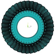
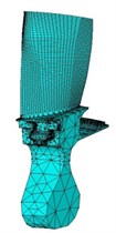
The compressor bladed disk system is assembled with 38 blades, each blade is composed of a blade body and a tenon, the blade and disk are connected through the dovetail tenon and mortise to form a bladed disk system, because the contact status of the parts changes along the changes of the revolving speed, from the ref. [32] known that the nonlinear friction has a great influence on the vibration amplitude of the mistuned bladed disk system, the bladed disk system analysis model must take the influences of the contact status of the tenon and mortise on the vibration of the blades and the blade disk system into account. Because the structure of the mistuned bladed disk system is complex, the quantity of elements and nodes is relatively huge after meshing, a computational analysis by adopting the integral model relatively wastes time; if the contact relation between the blade tenon and disk mortise is considered, the analysis will be more difficult. From the above discussion, the substructure mode synthesis method is generally adopted for a kinetic analysis on the mistuned bladed disk system. The Craig-Bampton method [15] in the structural dynamics is introduced, each blade and corresponding disk are used as a basic sector, the pre-stressed component mode synthesis method is adopted to divide the whole bladed disk system into 38 basic sectors, and each sector is used as a substructure, choose solid45 element mesh mapping on the blade, disk mesh choose the solid187 element, tenon and mortise contact with surface to surface contact. The basic sector of the substructure is divided into 52163 elements, and the number of nodes is 79174. The material properties for the model are listed in Table 1. The blade model and substructure finite element model of the compressor bladed disk system is shown in Fig. 1.
Table 1Blade material properties
Blade material property | Property value | Disk material property | Property value |
Mass density | 4400 kg·m−3 | Mass density | 4700 kg·m−3 |
Modulus of elasticity | 113 GPa | Modulus of elasticity | 150 GPa |
Poisson’s ratio | 0.3 | Poisson’s ratio | 0.3 |
Fig. 1Finite element model of bladed disk
The pre-stressed component mode synthesis method enables the inner coordinates of each substructure to be as the slave degree of freedom and the interfacial coordinate of each substructure to be as the master degree of freedom. The dynamic reduced-order technology is adopted for condensing the slave degree of freedom of each substructure on the interfacial master degree of freedom, interfacial displacement compatibility conditions and interface force equilibrium condition are utilized to integrate the reduced super-element to form the whole system. The general non-damping free vibration equation of the th substructure finite element model can be written as:
where and is the mass matrix and the stiffness matrix, accordingly, and shows the displacement vector. The stress state of the aero-engine compressor blade thin in one or two degrees of freedom will influence the natural frequency and the dynamic response of the structure under the action of centrifugal force, in consideration of the influences of centrifugal rigidization on the dynamic characteristics of the rotor system, linear stress analysis is conducted under the condition of the static state to translate rotating centrifugal load into pre-stressed force effect matrix of the structure to be annexed in the kinetic equation, therefore, the obtained kinetic equation by considering the centrifugal stiffening effect is:
where is the stiffness matrix after considering the pre-stressed force effect matrix. The displacement vector and coefficient matrix in the Eq. (2) are divided into the master degree of freedom on the boundary and the slave degree of freedom on the non-boundary (subscript and subscript respectively show the master degree of freedom and the slave degree of freedom):
where is the interface force. When the interface of substructure completely fixed, that is , the equation of motion of the fixed boundary condition can be written as:
The regularization mode set can be solved from equation, it consists of the low order mode set and the high order mode set as follow:
, the mode set yields:
where , , is characteristic values, is identity matrix.
Let be , that is:
where is master modes set of substructure.
It is assumed that the inertia term is not considered, and the force is only on the master degree of freedom, the Eq. (8) can be obtained by Eq. (3):
So that the Eq. (8) can be written as:
Thus, the can be written as:
Let be and be , that is:
Then:
Now we define the mode set of constraints, can be written as:
Ritz vectors can consist of and , that is:
Make use of coordinate transformation equation:
where is the substructure modal coordinates; is the coordinate transformation matrix [15] of the fixed interface method, is the eigenvector of the substructure boundary node under the fixed condition, is the unit matrix, and 0 is null matrix. The kinetic equation expressed as the Eq. (2) by utilizing the Eq. (11) is transformed to the modal coordinate:
where , .
The degree of freedom reduction method [16] is utilized, let be , that is:
where is the low order modal set truncated by high order, so:
where is the reduced-order modal coordinate of the slave degree of freedom ; so, the modal coordinate vector in the Eq. (12) changes into .
In consideration of rigid connection among the substructures, the non-independent coordinate is converted into the generalized coordinate of the overall bladed disk system by using the following transformation of coordinates [15]:
Thus, to establish the free vibration equation as:
where and are less than the mass matrix and stiffness matrix under the original system generalized coordinate because of the reduction of degree of freedom.
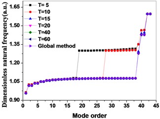
In the Eq. (17), because of the neglected high order mode, so and are less than the mass matrix and stiffness matrix under the original system generalized coordinate through the reduction of degree of freedom. The choice of mode truncation number is especially important for the accuracy of the analysis. The vibration characteristics of the bladed disk at different mode truncated numbers are calculated by pre-stressed component mode synthesis method.
As shown in Fig. 2, represents the mode truncation number, when is equal to 5 and 10, the natural frequency is calculated to be far from the global method, with the increase of the mode truncation number, the accuracy is further improved, when is equal to 15 and 20, the accuracy is higher. When is equal to 40 and 60, the calculated values of natural frequencies are in good agreement with the global method; It shows that the PCMS method is convergent.
Fig. 2Comparison of Global method with pre-stressed component mode synthesis method by different mode truncation numbers
3. Identification of mistuned parameter
For the engineering actual bladed disk system, mistuning destroys the cyclic symmetry and causes the stiffness and frequency of the blades to be different, and for the test frequency distribution, it is important to correctly identify the mistuned parameters for analyzing the mistuned bladed disk system. The stiffness and the frequency of the mistuned blades are simulated by introducing different disturbance factor to the elastic modulus of the blades, that is:
In the Eq. (18), is the elastic modulus of each blade, is the elastic modulus of the tuned blade, and is the perturbation parameters.
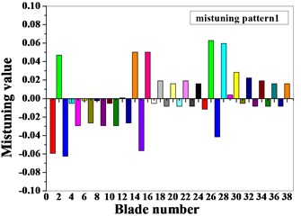
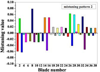
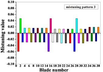
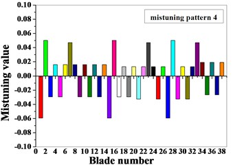
For the identification of mistuned parameters, the method based on the combination of the blade static frequency, dichotomy and finite element analysis are adopted: firstly, a static frequency test is conducted on the blades of the compressor bladed disk system to obtain the first-order bending static frequency of each blade; secondly, the method of combining dichotomy and finite element analysis are applied to identify the mistuned elastic modulus corresponding to the natural frequency for first-order bending of the blade static frequency test by introducing different perturbation parameters . Two kinds of mistuned aligning are provided for two groups of blade frequency test data, as shown in Table 2. The dimensionless data is the ratio of mistuned blade data to tuned blade data. The basic flow of the blade mistuned parameter identification based on the combination of blade static frequency, dichotomy and finite element analysis is shown in Fig. 3. Blade meshes choose SOLID45 element type and tenon mesh choose SOLID187 element type, blade and tenon are divided into 35072 elements, and the number of nodes is 49051. The blade finite element model is shown in Fig. 4, and the full constraint is implemented on a contact surface between the tenon and mortise. The specific identification steps are as follows: firstly, the natural frequency for first-order bending of the blade corresponding to the top and bottom limitation of the elastic modulus is calculated; secondly, through dichotomy iterative computations, the statics frequency for first-order bending measured from the blade statics frequency test is compared with the finite element analysis result of the natural frequency for first-order bending of the blade, the calculation convergence standard is that the error is less than 0.01, and then the mistuned elastic modulus of single blade corresponding to the statics frequency of the blade test is provided. The elastic modulus mistuning corresponding to the natural frequency for first-order bending of the blade statics frequency obtained through mistuning identification is shown in Fig. 5.
Table 2Dimensionless test frequency of mistuned blades (a.u.)
Blade number | Dimensionless test frequency of group 1 | Dimensionless test frequency of group 2 | Blade number | Dimensionless test frequency of group 1 | Dimensionless test frequency of group 2 | ||||
Pattern 1 | Pattern 2 | Pattern 3 | Pattern 4 | Pattern 1 | Pattern 2 | Pattern 3 | Pattern 4 | ||
1 | 0.9695 | 0.9695 | 0.9695 | 0.9695 | 20 | 1.0076 | 1.0076 | 1.0061 | 1.0061 |
2 | 1.0229 | 1.0229 | 1.0229 | 1.0244 | 21 | 0.9954 | 0.9954 | 0.9832 | 0.9832 |
3 | 0.9679 | 0.9679 | 0.9847 | 0.9847 | 22 | 1.0092 | 1.0092 | 1.0061 | 1.0061 |
4 | 0.9969 | 0.9969 | 1.0076 | 1.0076 | 23 | 0.9954 | 0.9954 | 0.9832 | 1.0229 |
5 | 0.9847 | 0.9847 | 0.9847 | 0.9847 | 24 | 1.0076 | 1.0076 | 1.0061 | 1.0061 |
6 | 0.9985 | 0.9985 | 1.0076 | 1.0076 | 25 | 0.9939 | 0.9939 | 0.9832 | 0.9832 |
7 | 0.9863 | 0.9863 | 0.9847 | 1.0229 | 26 | 1.0305 | 1.0305 | 1.0061 | 1.0061 |
8 | 0.9985 | 1.0382 | 1.0076 | 1.0076 | 27 | 0.9786 | 0.9786 | 0.9695 | 0.9695 |
9 | 0.9847 | 0.9847 | 0.9847 | 0.9847 | 28 | 1.0290 | 1.0290 | 1.0229 | 1.0244 |
10 | 0.9969 | 0.9969 | 1.0076 | 1.0076 | 29 | 1.0015 | 1.0015 | 0.9832 | 0.9832 |
11 | 0.9847 | 0.9847 | 0.9847 | 0.9847 | 30 | 1.0137 | 1.0137 | 1.0061 | 1.0061 |
12 | 1.0000 | 1.0000 | 1.0076 | 1.0076 | 31 | 0.9969 | 0.9969 | 0.9832 | 0.9832 |
13 | 0.9863 | 0.9863 | 0.9847 | 0.9847 | 32 | 1.0107 | 1.0260 | 1.0061 | 1.0061 |
14 | 1.0244 | 1.0244 | 1.0076 | 1.0076 | 33 | 0.9954 | 0.9725 | 0.9863 | 1.0229 |
15 | 0.9710 | 0.9710 | 0.9695 | 0.9695 | 34 | 1.0092 | 1.0092 | 1.0092 | 1.0092 |
16 | 1.0244 | 1.0244 | 1.0229 | 1.0244 | 35 | 0.9954 | 0.9954 | 0.9863 | 0.9863 |
17 | 0.9969 | 0.9969 | 0.9847 | 0.9847 | 36 | 1.0076 | 1.0076 | 1.0092 | 1.0092 |
18 | 1.0092 | 1.0092 | 1.0061 | 1.0061 | 37 | 0.9954 | 0.9954 | 0.9863 | 0.9863 |
19 | 0.9954 | 0.9954 | 0.9847 | 0.9847 | 38 | 1.0076 | 1.0076 | 1.0092 | 1.0092 |
Fig. 3Flow chart of mistuned parameter identification
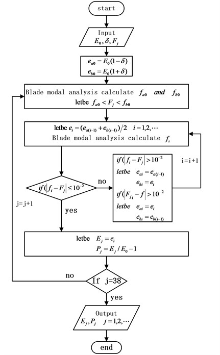
Fig. 4Finite element model of bladed
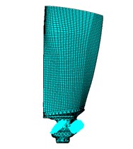
Fig. 5Mistuning value of blades
4. Localization influences of different influences on mistuned bladed disk
The natural frequencies of the bladed disk system are equal to the exciting force frequency, and the resonance occurs when the engine orders of excitation is equal to the nodal diameter. The bladed disk mistunes to cause the vibration mode not to conform to the development form of the harmonic and to expand to the different nodal diameter with mistuning, and the level of sensitivity of the vibration mode on different orders to mistuning is different. Therefore, it is necessary to deeply research the vibration response characteristics of the bladed disk system by aiming at the mistuned bladed disk system under the influence factors of the different engine orders of excitation, mean frequency and stiffness ratio of the blade and disk, in order to distinguish the vibration localization condition of the mistuned blades under the different engine orders of excitation, the relative localization factors are adopted, the relative localization factors can be calculated by Eq. (19):
where , , , , are the maximum strain energy of the mistuned blade, the total strain energy of the mistuned bladed disk system, the maximum strain energy of the tuned blade, and is the total strain energy of the tuned bladed disk system respectively.
4.1. Localization influences of engine orders of excitation on mistuned bladed disk
The actual stress of the bladed disk system is extremely complex, when the harmonic response analysis is conducted on the stress of the bladed disk system, the load of aerodynamic excitation by each blade is simplified into a single-point excitation form, namely the aeroelastic exciting force is implemented on the same node corresponding to the leading edge of the blade tip of each blade, and load meets with the requirements to the travelling wave in space.
The kinetic equation of the bladed disk structure can be expressed as:
where , and respectively represent the mass matrix, damping matrix and stiffness matrix, is exciting force vector, under the circumstance of only considering mistuning of stiffness, the kinetic equation of the mistuned bladed disk system can be expressed as:
where is the stiffness mistuning matrix, and the th component of the travelling wave exciting force can be expressed as:
where is the vibration amplitude of the exciting force load by th rotor blade, is the excitation frequency, is the phase angle of the travelling wave exciting force on the th blade, as follow:
where is the engine orders of excitation, and the real part value and the imaginary part value for load applying can be confirmed by the following equation.
Real part value:
Imaginary part value:
In the harmonic response analysis, , and the modal damping ratio %. The distribution of the travelling wave exciting force is in the simple harmonic form, the difference of the exciting force between adjacent blades is the constant phase angle, and the degree of the phase angle is determined by the engine orders of excitation , therefore, the harmonic response travelling wave excitation of the bladed disk system is determined by the value range of the engine orders of excitation and the excitation frequency , the range of the engine orders of excitation is from 1 to 6, and the range of the dimensionless excitation frequency is from 1.07 to 1.22. The vibration amplitude and the total strain energy distribution condition of the tuned bladed disk system under the different engine orders of excitation are shown in Fig. 6 and Fig. 7. As shown in Fig. 6, the vibration amplitude of the bladed disk system gradually increases with the increase of the engine orders of excitation, and the excitation frequency with the maximum vibration amplitude resonance also increases. As shown in Fig. 6, the total strain energy of the bladed disk system gradually increases with the increase of the engine orders of excitation, and the excitation frequency with the maximum strain energy also increases.
Fig. 6Amplitude distribution of tuned bladed disk system under different engine orders of excitation
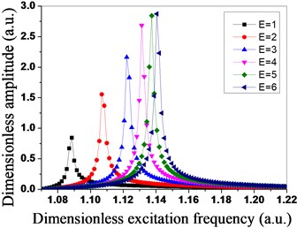
Fig. 7Total strain energy distribution of tuned bladed disk system under different engine orders of excitation
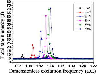
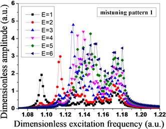
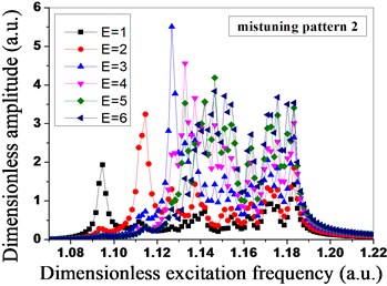
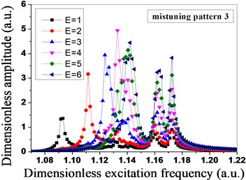
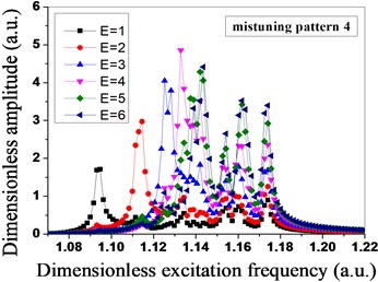
Fig. 8Amplitude distribution of mistuned bladed disk system under different engine orders of excitation
a)
b)
c)
d)
As shown in Fig. 8, due to the mistuned mode 1 and mistuned mode 2 are in the same group, mistuned mode 3 and mistuned mode 4 are in the same group, the vibration amplitude of the mistuned mode 1 and the vibration amplitude of the mistuned mode 2 are the maximum when the engine order of excitation is 3, however, the vibration amplitude of the mistuned mode 3 and the vibration amplitude of the mistuned mode 4 are the maximum when the engine order of excitation is 4, the different maximum vibration amplitude of the bladed disk system is caused by the different blade mistuned modes under the different engine orders of excitation, and it shows that the level of sensitivity of the different engine orders of excitation to blade mistuning is different. The vibration amplitude is the maximum when the mode of vibration of the mistuned mode 1 and the mistuned mode 2 expends to 3 nodal diameters, and the vibration amplitude is the maximum when the mode of vibration of the mistuned mode 3 and the mistuned mode 4 expends to 4 nodal diameters.
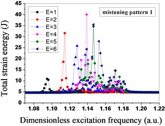
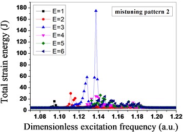
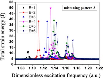
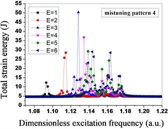
In Fig. 9, the mistuned mode has significant influences on the total strain energy of the mistuned bladed disk system under the different engine orders of excitation. The mistuned mode 1 and mistuned mode 3 are relatively sensitive to the engine order of excitation 4, the total strain energy of the bladed disk system reaches the maximum at the moment, and the mistuned mode 2 and mistuned mode 4 are relatively sensitive to the engine order of excitation 3. In the mistuned mode 2, when the engine order of excitation is 3, the maximum total strain energy of the bladed disk system is three times that of the bladed disk system under other three mistuned modes, so for the mistuned mode 2, the bladed disk system is the most sensitive to the engine order of excitation 3. Meanwhile, the dimensionless excitation frequency of the mistuned mode 1 and mistuned mode 2 with the maximum strain energy is about 1.138, the dimensionless excitation frequency of the mistuned mode 3 and mistuned mode 4 with the maximum strain energy is about 1.13, and the mistuned mode influences both the total strain energy of the bladed disk system, and the excitation frequency for the maximum total strain energy.
Fig. 9Total strain energy distribution of mistuned bladed disk system under different engine orders of excitation
a)
b)
c)
d)
Fig. 10Relative localization factors of mistuned bladed disk system under different engine orders of excitation
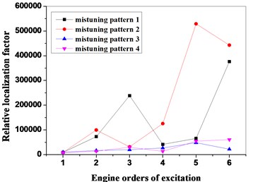
As shown in Fig. 8 and Fig. 9, the mistuned mode has great influences on the vibration amplitude and the total strain energy of the bladed disk system under the different engine orders of excitation, in order to further research the influences of the mistuned modes and the different engine orders of excitation on the degree of localization of the mistuned bladed disk system, the relative localization factors of the bladed disk system in four mistuned modes under different engine orders of excitation are calculated by adopting the Eq. (19), as shown in Fig. 10. Seen from Fig. 10, under the function of the different engine orders of excitation, the relative localization factors of the mistuned mode 3 and mistuned mosde 4 of the second group are relatively smaller, and not obvious with the changes of the engine orders of excitation; however, the relative localization factors of the mistuned mode 1 and mistuned mode 2 of the first group are relative greater, and obviously change with the changes of the engine orders of excitation, and the degree of localization is relatively high.
Table 3Frequency of blades for difference from mean frequency (a.u.)
Blade number | Mean frequency | |||||||
0.9774 | 0.9851 | 0.9927 | 1.0003 | 1.0080 | 1.0156 | 1.0232 | 1.0309 | |
1 | 0.9466 | 0.9542 | 0.9618 | 0.9695 | 0.9771 | 0.9847 | 0.9924 | 1.0000 |
2 | 1.0000 | 1.0076 | 1.0153 | 1.0229 | 1.0305 | 1.0382 | 1.0458 | 1.0534 |
3 | 0.9450 | 0.9527 | 0.9603 | 0.9679 | 0.9756 | 0.9832 | 0.9908 | 0.9985 |
4 | 0.9740 | 0.9817 | 0.9893 | 0.9969 | 1.0046 | 1.0122 | 1.0198 | 1.0275 |
5 | 0.9618 | 0.9695 | 0.9771 | 0.9847 | 0.9924 | 1.0000 | 1.0076 | 1.0153 |
6 | 0.9756 | 0.9832 | 0.9908 | 0.9985 | 1.0061 | 1.0137 | 1.0214 | 1.0290 |
7 | 0.9634 | 0.9710 | 0.9786 | 0.9863 | 0.9939 | 1.0015 | 1.0092 | 1.0168 |
8 | 1.0153 | 1.0229 | 1.0305 | 1.0382 | 1.0458 | 1.0534 | 1.0611 | 1.0687 |
9 | 0.9618 | 0.9695 | 0.9771 | 0.9847 | 0.9924 | 1.0000 | 1.0076 | 1.0153 |
10 | 0.9740 | 0.9817 | 0.9893 | 0.9969 | 1.0046 | 1.0122 | 1.0198 | 1.0275 |
11 | 0.9618 | 0.9695 | 0.9771 | 0.9847 | 0.9924 | 1.0000 | 1.0076 | 1.0153 |
12 | 0.9771 | 0.9847 | 0.9924 | 1.0000 | 1.0076 | 1.0153 | 1.0229 | 1.0305 |
13 | 0.9634 | 0.9710 | 0.9786 | 0.9863 | 0.9939 | 1.0015 | 1.0092 | 1.0168 |
14 | 1.0015 | 1.0092 | 1.0168 | 1.0244 | 1.0321 | 1.0397 | 1.0473 | 1.0550 |
15 | 0.9481 | 0.9557 | 0.9634 | 0.9710 | 0.9786 | 0.9863 | 0.9939 | 1.0015 |
16 | 1.0015 | 1.0092 | 1.0168 | 1.0244 | 1.0321 | 1.0397 | 1.0473 | 1.0550 |
17 | 0.9740 | 0.9817 | 0.9893 | 0.9969 | 1.0046 | 1.0122 | 1.0198 | 1.0275 |
18 | 0.9863 | 0.9939 | 1.0015 | 1.0092 | 1.0168 | 1.0244 | 1.0321 | 1.0397 |
19 | 0.9725 | 0.9802 | 0.9878 | 0.9954 | 1.0031 | 1.0107 | 1.0183 | 1.0260 |
20 | 0.9847 | 0.9924 | 1.0000 | 1.0076 | 1.0153 | 1.0229 | 1.0305 | 1.0382 |
21 | 0.9725 | 0.9802 | 0.9878 | 0.9954 | 1.0031 | 1.0107 | 1.0183 | 1.0260 |
22 | 0.9863 | 0.9939 | 1.0015 | 1.0092 | 1.0168 | 1.0244 | 1.0321 | 1.0397 |
23 | 0.9725 | 0.9802 | 0.9878 | 0.9954 | 1.0031 | 1.0107 | 1.0183 | 1.0260 |
24 | 0.9847 | 0.9924 | 1.0000 | 1.0076 | 1.0153 | 1.0229 | 1.0305 | 1.0382 |
25 | 0.9710 | 0.9786 | 0.9863 | 0.9939 | 1.0015 | 1.0092 | 1.0168 | 1.0244 |
26 | 1.0076 | 1.0153 | 1.0229 | 1.0305 | 1.0382 | 1.0458 | 1.0534 | 1.0611 |
27 | 0.9557 | 0.9634 | 0.9710 | 0.9786 | 0.9863 | 0.9939 | 1.0015 | 1.0092 |
28 | 1.0061 | 1.0137 | 1.0214 | 1.0290 | 1.0366 | 1.0443 | 1.0519 | 1.0595 |
29 | 0.9786 | 0.9863 | 0.9939 | 1.0015 | 1.0092 | 1.0168 | 1.0244 | 1.0321 |
30 | 0.9908 | 0.9985 | 1.0061 | 1.0137 | 1.0214 | 1.0290 | 1.0366 | 1.0443 |
31 | 0.9740 | 0.9817 | 0.9893 | 0.9969 | 1.0046 | 1.0122 | 1.0198 | 1.0275 |
32 | 1.0031 | 1.0107 | 1.0183 | 1.0260 | 1.0336 | 1.0412 | 1.0489 | 1.0565 |
33 | 0.9496 | 0.9573 | 0.9649 | 0.9725 | 0.9802 | 0.9878 | 0.9954 | 1.0031 |
34 | 0.9863 | 0.9939 | 1.0015 | 1.0092 | 1.0168 | 1.0244 | 1.0321 | 1.0397 |
35 | 0.9725 | 0.9802 | 0.9878 | 0.9954 | 1.0031 | 1.0107 | 1.0183 | 1.0260 |
36 | 0.9847 | 0.9924 | 1.0000 | 1.0076 | 1.0153 | 1.0229 | 1.0305 | 1.0382 |
37 | 0.9725 | 0.9802 | 0.9878 | 0.9954 | 1.0031 | 1.0107 | 1.0183 | 1.0260 |
38 | 0.9847 | 0.9924 | 1.0000 | 1.0076 | 1.0153 | 1.0229 | 1.0305 | 1.0382 |
4.2. Localization influences of mean frequency of different blades on mistuned bladed disk system
As discussed in Section 4.1, frequency of the mistuned blades has significant influences on the vibration localization of the bladed disk system, in order to study the influences of the blade frequency on the mistuned bladed disk system, the concept of the mean frequency of blades is introduced, and the mean frequency of blades is the average value of all blade frequencies of the bladed disk system. From the analysis result of the engine orders of excitation, the total strain energy of the bladed disk system in the mistuned mode 2 is three times than the bladed disk system in other mistuned modes, and the degree of localization is the highest in four groups, so the frequency of each blade in the mistuned mode 2 is used as the fundamental analytic target for the following analysis, the blade frequency is in accordance with the original distribution, the difference between the frequencies of the blades with the same serial number is 0.00763, and the obtained dimensionless mean frequency of eight groups of blades is shown in Table 3.
The vibration response of the mistuned bladed disk system is analyzed through the mean frequency of eight groups of blades in Table 3, and the analysis result is shown in Fig. 11 to Fig. 14. The relative localization characteristics of the bladed disk system under different mean frequencies are shown in Fig. 11, because the peak value is between 1.000321 and 1.007955 of the mean frequency of the blades, in order to find out the mean frequency of the blades corresponding to the real peak value, four groups of dimensionless mean frequencies are added into the interval of 0.00153 of the blade frequency between two mean frequencies, when the mean frequency is 1.00185 by calculation, the relative localization factor of the bladed disk system is the maximum, and the degree of localization is the highest.
Fig. 11Relative localization characteristics of bladed disk system under different mean frequencies
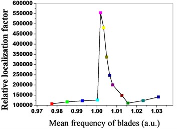
Fig. 12Amplitude-frequency characteristics of bladed disk system under mean frequency is 1.00185
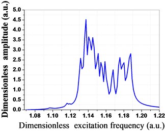
Fig. 13Amplitude of mean frequency is 1.00185 for every mistuned bladed disk
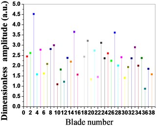
Fig. 14Strain energy of mean frequency is 1.00185 for every mistuned bladed disk
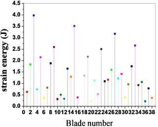
The amplitude- frequency curve of the bladed disk system is shown in Fig. 11 when the mean frequency of the blades is 1.00185, as shown in the figure, the dimensionless vibration amplitude of the blades is the maximum when the dimensionless excitation frequency is 1.1374. The vibration amplitude and the strain energy distribution conditions of the blades are shown in Fig. 13 and Fig. 14 when the mean frequency of the blades is 1.00185, as shown in the figure, the vibration amplitude and the strain energy of blade No. 3, blade No. 15, blade No. 27 and blade No. 33 are the maximum in all blades, and the vibration energy of the bladed disk system mainly concentrates on these blades.
4.3. Influences of different blades and disk stiffness ratio on mistuned bladed disk system
The stiffness of the blades and disk is in coupling effect and has obvious influences on the forced vibration of the bladed disk system, in order to further study the influences of the blades and disk stiffness on the forced vibration of the mistuned bladed disk system, the below researches are conducted. Because in the actual bladed disk system, mistunes mostly mainly occur in blades, namely the blades stiffness changes, but the disk stiffness basically does not change, so the disk stiffness is constant, the forced vibration of the mistuned bladed disk system is analyzed by adopting different stiffness value on the blades. When the stiffness ratio between the blades and disk is from 0.6 to 1.5, the forced vibration conditions of the bladed disk system are shown in Fig. 15 to Fig. 18.
Fig. 15Strain energy of bladed disk system under different stiffness ratio
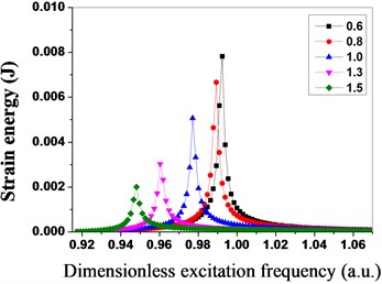
Fig. 16Maximum strain energy distribution of blades under different stiffness ratio
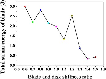
Fig. 17Maximum vibration amplitude of bladed disk under different stiffness ratio
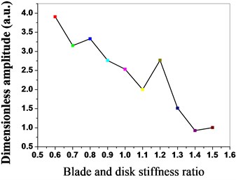
Fig. 18Maximum strain energy of bladed disk under different stiffness ratio
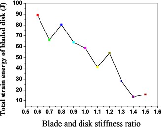
As shown in Fig. 15, the maximum strain energy of the bladed disk system declines with the increase of the stiffness ratio, the strain energy of the bladed disk system is the minimum when the stiffness ratio is 1.5; meanwhile, the excitation frequency with the maximum strain energy decreases thereupon. The maximum strain energy distribution of the blades is shown in Fig. 16 when the stiffness ratio is different, and the strain energy of the blades declines with the increase of the stiffness ratio. The maximum vibration amplitude and the maximum strain energy distribution conditions of the bladed disk system are shown in Fig. 17 and Fig. 18 when the stiffness ratio is different, and the maximum vibration amplitude and maximum strain energy of the bladed disk system gradually decline with the increase of the stiffness ratio.
5. Conclusions
Aiming at the aero-engine compressor bladed disk system, the pre-stressed component mode synthesis method is adopted for establishing the finite element reduced-order models (ROMs), the identification of mistuned parameters through the method of combination of blade static frequency, dichotomy and finite element analysis, the localization characteristics of the vibration response of the mistuned bladed disk system are analyzed by combining the relative localization factors, the influences of different engine orders of excitation, mean frequency of the blades, and stiffness ratio between the blades and disk on localization of the vibration response of the mistuned bladed disk system, the following conclusions are obtained:
1) The pre-stressed component mode synthesis method is adopted for sharply reducing the freedom degree of the mass matrix and stiffness matrix;
2) The identification of mistuned parameters through the method of combination of blade static frequency, dichotomy and finite element analysis to accurately simulate the actual mistuned bladed disk system for engineering.
3) The relative localization factors are better evaluated than the degree of localization of vibration response of the mistuned bladed disk system between different engine orders of excitation.
4) The influences of different engine orders of excitation, the mean frequency of the blades, and the stiffness ratio between the blades and disk on the localization of vibration response of the mistuned bladed disk system are analyzed to obtain the vibration localization characteristics of the mistuned bladed disk system.
References
-
Ewins D. J. The effects of detuning upon the forced vibrations of bladed disks. Journal of Sound and Vibration, Vol. 9, Issue 1,1969, p. 65-72.
-
Griffin J. H., Hoosac T. M. Model development and statistical investigation of turbine blade mistuning. ASME Journal of Vibration and Acoustics, Vol. 106, Issue 2, 1984, p. 204-210.
-
Wei S. T., Pierre C. Localization phenomena in mistuned assemblies with cyclic symmetry part 1: free vibrations. ASME Journal of Vibration and Acoustics, Vol. 110, 1988, p. 429-430.
-
Ewins D. J. Vibration characteristics of bladed disks. Archive Journal of Mechanical Engineering Science, Vol. 15, Issue 3, 1973, p. 165-186.
-
Wagner L. F., Griffin J. H. A continuous analog model for grouped-blade vibration. Journal of Sound and Vibration, Vol. 165, Issue 3, 1993, p. 421-438.
-
Tomioka T., Kobayashi Y., Yamada G. Analysis of free vibration of rotating disk – blade coupled systems by using artificial springs and orthogonal polynomials. Journal of Sound and Vibration, Vol. 191, Issue 1, 1996, p. 53-73.
-
Kuang J. H., Huang B. W., et al. Mode localization of a cracked blade disk. Journal of Engineering for Gas Turbines and Power, Vol. 121, Issue 2, 1999, p. 335-341.
-
Kirkhope J., Wilson G. J. A finite element analysis for the vibration modes of a bladed disc. Journal of Sound and Vibration, Vol. 49, Issue 4, 1976, p. 469-482.
-
Soares C. A. M., Petyt M. Finite element dynamic analysis of practical bladed discs. Journal of Sound and Vibration, Vol. 61, Issue 4, 1978, p. 561-570.
-
Fitzner C., Epureanu B. I., Filippi S. Nodal energy weighted transformation: A mistuning projection and its application to FLADE™, turbines. Mechanical Systems and Signal Processing, Vol. 42, Issues 1-2, 2014, p. 167-180.
-
Beck J. A., Brown J. M., Scott-Emuakpor O. E., et al. Dynamic response characteristics of dual flow-path integrally bladed rotors. Journal of Sound and Vibration, Vol. 336, 2015, p. 150-163.
-
Wang J. J., Li Q. H. Methods and Applications of Reduction Modeling for Mistuned Bladed Disk Vibration in Aero-Engine. National Defense Industry Press, Beijing, 2009.
-
Yang M. T., Griffin J. H. A reduced-order model of mistuning using a subset of nominal system modes. Journal of Engineering for Gas Turbines and Power, Vol. 123, Issue 4, 1999, p. 135-81.
-
Feiner D. M., Griffin J. H. A fundamental model of mistuning for a single family of modes. Journal of Turbomachinery, Vol. 124, Issue 4, 2002, p. 953-964.
-
Craig R. R., Bampton M. D. D. Coupling of substructures for dynamic analyses. AIAA Journal, Vol. 6, Issue 7, 1968, p. 1313-1319.
-
Craig R. R. A review of time-domain and frequency-domain component-mode synthesis methods. International Journal of Analytical and Experimental Modal Analysis, Vol. 2, Issue 2, 1987, p. 59-72.
-
Bladh R., Castanier M. P., Pierre C. Component-mode-based reduced order modeling techniques for mistuned bladed disks – part I: theoretical models. Journal of Engineering for Gas Turbines and Power, Vol. 123, Issue 1, 2000, p. 89-99.
-
Bladh R., Castanier M. P., Pierre C. Component-mode-based reduced order modeling techniques for mistuned bladed disks – Part II: Application. Journal of Engineering for Gas Turbines and Power, Vol. 123, Issue 1, 2000, p. 100-108.
-
Yang M. T., Griffin J. H. A normalized modal eigenvalue approach for resolving modal interaction. Journal of Engineering for Gas Turbines and Power, Vol. 119, Issue 3, 1997, p. 491-499.
-
Griffin J. H., Feiner D. M. Mistuning identification of bladed disks using a fundamental mistuning model – Part I: Theory. Journal of Turbomachinery, Vol. 126, Issue 1, 2004, p. 150-158.
-
Ewins D. J., Imregun M. Vibration modes of packeted bladed disks. ASME Journal of Vibration and Acoustics, Vol. 106, 1984, p. 175-180.
-
Wei S. T., Pierre C. Localization phenomena in mistuned assemblies with cyclic symmetry Part 2: Forced Vibrations. ASME Journal of Vibration, Acoustics, Stress and Reliability in Design, Vol. 110, 1988, p. 439-449.
-
Pierrre C., Murthy D. V. Aeroelastic modal characteristics of mistuned blade assemblies: mode localization and loss of eigenstructure. AIAA Journal, Vol. 30, Issue 10, 1992, p. 2483-2496.
-
Ottarsson G., Pierre C. A transfer matrix approach to free vibration localization in mistuned bladed assemblies. Journal of Sound and Vibration, Vol. 197, Issue 5, 1996, p. 589-618.
-
Wang J. J., Yao J. Y., Li Q. H. Probability characteristics of vibratory mode of bladed disk assemblies with random stiffness mistuning. Journal of Aerospace Power, Vol. 23, Issue 2, 2008, p. 256-262.
-
Wang H. J., He E. M., Zhao Z. B. Effects of frequency veering features on mode localization of mistuned bladed disks. China Mechanical Engineering, Vol. 20, Issue 1, 2009, p. 82-85.
-
Song Z. H. The Strength Design of Aero Gas Turbine Engine. Beijing University of Aeronautics and Astronautics Press, Beijing, 1988.
-
Castanier M. P., Pierre C. Modeling and analysis of mistuned bladed disk vibration: status and emerging directions. Journal of Propulsion and Power, Vol. 22, Issue 2, 2006, p. 354-396.
-
Hussein M. I., Pierre C., Castanier M. P. Correlation of tuned free vibration characteristics with mistuning sensitivity for a bladed disk. 44th AIAA/ASME/ASCE/AHS Structures, Structural Dynamics and Materials Conference, Norfok, Virginia, 2003.
-
Zhang H. Y., Yuan H. Q., Kou H. J. Study of localization for the forced vibration of mistuned bladed disk based on engine orders of excitation. Journal of Northeastern University (Natural Science), Vol. 37, Issue 3, 2016, p. 378-382.
-
Yao J. Y., Wang J. J., Li Q. H. Dynamic characteristics assessment of mistuned bladed disk using nodal diameter spectrum of mode shapes. Journal of Propulsion Technology, Vol. 32, Issue 5, 2011, p. 645-653.
-
Yuan H. Q., Zhao T. Y., Yang W. J., et al. Annealing evolutionary parallel algorithm analysis of optimization arrangement on mistuned blades with non-linear friction. Journal of Vibroengineering, Vol. 17, Issue 8, 2015, p. 4078-4095.
About this article

This work was supported by the National Natural Science Foundation of China (No. 51275081), the key project of the National Natural Science Foundation of China (No. 51335003) and Special Science and Technology Innovation Project of Shenyang (F15-199-1-01).
