Abstract
A rigid-flexible coupling multi-body dynamic model which contains the structure system and transmission system of gear device is developed taking account of the internal excitations such as the time-varying mesh stiffness, tooth backlash and bearing stiffness and the external torque and speed excitation. Then the dynamic meshing forces of gear pairs and bearing reaction forces are calculated based on the dynamic theory of multi-body system. Afterwards, a vibro-acoustic coupling model of the gear system is established by taking the frequency histories of bearing reaction forces as the boundary conditions, and then the surface sound pressure of gearbox and the radiation noise of outer sound field are calculated. In fact, the proposed model would provide a quicker approach to analyze the radiation noise of the gear system during the design phase. Finally, the radiation noise experimental study is performed on the experimental prototype to verify the rationality of the analysis. The comparison analysis shows that computational results are in good agreement with the data of experiment test.
1. Introduction
The vibration of gear transmission system caused by dynamic excitation during the process of gear system operation is transmitted from bearings to bearing supports, and to the gear housing. The vibration of gear housing would cause the radiated noise which will spread outward. It is well known that the study objects in the practical engineering are often more complex, which there are some problems, such as nonlinear internal excitation, coupling internal and external excitations, transfer mode between dynamic excitations and vibration response [1-3]. All those factors make the radiate noise prediction in the gearbox design stage difficult and inefficient.
Recently, many scholars carried out a lot of research work for the generating mechanism and prediction method of air-borne noise starting with the structure design and input dynamic excitations. Moyne [4] discussed the effect of rib plate structure on the noise of gearbox using boundary element method. Abbes [5] built the three dimensional finite element analysis model of gearbox combining the Rayleigh Integral Algorithm to calculate the radiated noise. At the same time, Barthod [6] researched the influence of the motor torque on the noise of the gearbox. Lin [7] analyzed the vibration and noise problem of one subway gearbox by the structure finite element method and the acoustic finite element method. The author took the time varying mesh stiffness, mesh impact and error into consideration, carried out the numerical simulation of the dynamic response of the gear system including the transmission system and the structure system. Combining the finite element method and boundary element method, the radiate noise of the structure was solved and tested [8]. However, our group found out that the computational process of radiate noise is more complexity and low efficiency due to the actual large scale calculation model, especially the marine gearbox with larger physical dimension. In order to get the radiate noise rapidly in the design process, many scholar studies the vibration characteristics of some simple structures [9] and the bearing [10], which are based on the rigid-flexible coupling technique [11, 12].
Therefore, the main objective of this paper is to develop a method for rapidly predicting gearbox noise generated in the gear system by the rigid-flexible coupling technique and the boundary element method, and then the validity of the model is proved by means of testing. The simulation results will provide the basis and reference for performing acoustic optimization of complex gear system.
2. The acoustic analytical theory and method
The acoustic Helmholtz equation can be expressed as:
where the is the Lagrangian function; the is the sound pressure of the point in the sound field; is the velocity of the unit volume at ; the is the density of the acoustic medium; the is the angular frequency; is the wave number.
The weighted integral is carried out in the sound field and it is transformed into the integral along the normal direction of the surface by the Gauss theory, which is:
where the is weighting function; is the vibration velocity; is the propagation velocity of the sound wave in the medium.
Taking the acoustic stiffness matrix, damp matrix and mass matrix into Eq. (2), and the acoustic system equation is obtained:
where , and represent the acoustic stiffness matrix, damp matrix and mass matrix respectively; is the acoustic excitation.
For structure system, the dynamic equation can be expressed as:
where , and are the structure stiffness matrix, damp matrix and mass matrix respectively; is the displacement; is the structure excitation including the constrained degrees of freedom and external load.
The sound pressure load acting on the structure could be regarded as the additional normal load, and then the structure system dynamic equation can be expressed as:
where the is the coupling stiffness matrix.
At the coupling position of the fluid and the structure, the normal vibration velocity of the structure system keeps the same with the normal vibration velocity of the fluid system, the vibration velocity of structure could be taken as the boundary of additional velocity of the sound field, and then the adjusted acoustic system equation is:
where is the coupling mass matrix.
The relationship between the coupling stiffness matrix and the coupling mass matrix could be expressed as:
Combining Eq. (5) with Eq. (6) yields the following coupling equation:
3. Rigid-flexible coupling dynamic simulation of marine gear system
3.1. Dynamic analysis method
During the dynamic simulation of marine gear system, the gearbox could be divided into transmission system and structure system. The relationship between the two systems could be simulated by the bearings, which the “bushing force” at the position between the shafts and bearing supports would be define to simulate the mechanical transfer property (stiffness and damping of bearings). Therefore, the dynamic simulation model would be expressed as:
where the , are the mass matrix of transmission system and structure system respectively; , are the damp matrix of transmission system and structure system respectively; , are the stiffness matrix of transmission system and structure system respectively; , are the force vector acting on the transmission system and structure system; , , are the vibration acceleration vector, vibration velocity vector and vibration displacement vector of structure system; , , are the vibration acceleration vector, vibration velocity vector and vibration displacement vector of transmission system.
It’s worth noting that the stiffness and damping of bearings could be obtained with the technique of modal parameter identification.
3.2. Dynamic model of gear system
Fig. 1 shows the transmission structure diagram of the GVW marine gearbox. It is a kind of double motor concurrence marine gearbox with PTO (motor dynamic output equipment). The gearbox is mainly composed of the same two input shaft I and II, output shaft and the PTO shaft.
Fig. 1Structure diagram of the geared transmission system
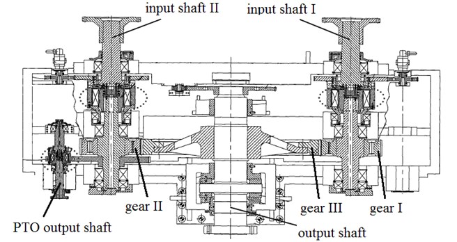
The geared transmission parameters of this marine gearbox are as follows: tooth number of gear I and II 41/41, tooth number of gear III 161, normal module 12 mm, normal pressure angles 20°, helical angle 20°, centre distance 1250 mm, the elasticity modulus of gear 2.06×10¹¹ Pa, density 7.85×10³ kg/m3, Poisson’s ratio 0.3; the material of housing is steel 45 and the elasticity modulus 2.06×10¹¹ Pa, density 7.85×10³ kg/m3, Poisson’s ratio 0.3;input rotational speed 800 r/min, power 200 kW.
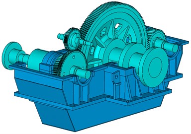
According to design parameters of the gear system, the accurate solid model of the gear pairs is built with the help of the software GEMTE which is designed and developed by our group. Then, all the parts, such as gear pairs, transmission shafts, bearings and housing, would be assembled according to the actual location of the structural system and transmission system. The rigid model of marine gearbox would be obtained, as shown in the Fig. 2.
Fig. 2Rigid model of GVW gear system
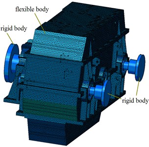
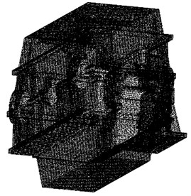
Afterward, the housing could be meshed to make it flexible using the element solid185. We would obtain the rigid-flexible coupling dynamic model of marine gearbox with a total of 133615 nodes and 412205 elements, as shown in the Fig. 3.
Fig. 3The rigid-flexible coupling dynamic model of marine gearbox
The defining methods of main analysis parameters in the rigid-flexible coupling dynamic model are follows: the relationship of gear meshing could be simulated by the transmission error, the stiffness and damping of bearings could be obtained with the technique of modal parameter identification.
It is well known that there are other factors caused by some external dynamic excitation to produce vibration of gear system except the internal dynamic excitation during the process of gear system operation, such as mass unbalance rotors, geometry eccentricity, load fluctuation of the motor, etc. In this present paper we only consider the load fluctuation of the motor as the external dynamic excitation. On the occasion that the motor input power is 200 kW and rotational speed is 800 r/min, the real output power can be measured directly by the hydraulic dynamometer on the characteristics test rig of marine gearbox, Fig. 4 shows the schematic diagram of test bench.
Fig. 4The schematic diagram of test bench
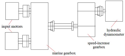
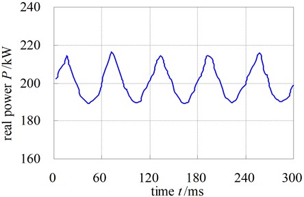
Our group obtain the experimental signal of real power of gearbox by testing the real output power fluctuation of hydraulic dynamometer. The test result is shown in Fig. 5, the real output power fluctuation range is between 5 %-8 % and the waveform is approximate a sine function.
It’s worth noting that there is a speed-increase gearbox in this test bench. Therefore, the fluctuation range is assumed to be 6 % while calculating the real output torque and input rotation rate of the motor.
Fig. 5The real power of gearbox
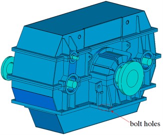
After the establishment the of rigid-flexible coupling dynamic model, the total response time of interest is chosen to be 5 s with the time step is set to be 6.10×10⁻⁵ s once the simulation results reach steady state. For all the numerical results proposed in this paper a 5 % viscous damping ratio is considered. The dynamic model is calculated with fully constrained bolt holes shown in the Fig. 2.
3.3. Analysis result
The bearing dynamic reaction force while the rotation speed fluctuation and torque fluctuation are considered could be obtained by solving the rigid-flexible coupling dynamic model of marine gearbox using the variable step backward difference method (BDF).
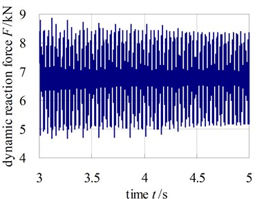
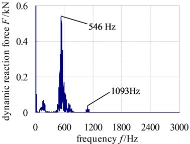
Fig. 6 and Fig. 7 show the dynamic reaction force of bearing at the input shaft I and output shaft. The dynamic reaction force of other bearings would be not shown one by one because of the limit of space.
In the two figures, the time domain curve only shows the data in 3-5 s and the frequency curve shows the data in 0-3000 Hz. From the figures, the bearing dynamic reaction force gets peak values at 546.7 Hz and 1093.4 Hz which are the mesh frequency and frequency doubling. Hence, the performances of the gear meshing will be likely to influence the generated noise levels greatly. Additionally, it can be observed that the response spectrum contains dynamic energy not only at the expected excitation frequencies but also at other frequency points. This is an effect that is likely to be caused by the non-linear dynamic coupling at the gear mesh.
Fig. 6The dynamic reaction force of bearing at input shaft I
a) Time domain
b) Frequency domain
Fig. 7The dynamic reaction force of bearing at output shaft
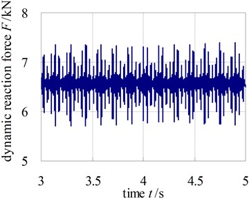
a) Time domain
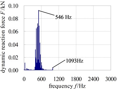
b) Frequency domain
4. Acoustic characteristics research of gearbox
4.1. Acoustic analysis model of marine gearbox
On the basis of the structure grid of the marine gearbox, the frequency data of the dynamic reaction force of all bearings obtained from the rigid-flexible coupling dynamic model is taken as the boundary condition of the acoustic analysis. The force would be loaded on the rigid-flexible coupling points at the bearing holes. The structure finite element model of the marine gearbox is established, as shown in Fig. 8.
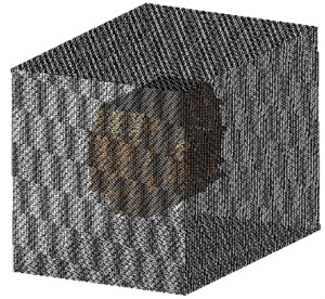
Afterward, the surface grid of the structure finite element model is extracted, and then the acoustic grid which is the envelope of the structure grid would be obtained. Through the mapping approach which realizes the data exchange between the structure grid and the acoustic grid, the vibro-acoustic coupling model is built. In order to gain the radiate noise of the gearbox, a square grid as sound field model which the length of side is approximately 1 m, is set outside the gearbox. Then the acoustic field point gird would be built. Fig. 9 shows the acoustic boundary element model of the marine gearbox, among which there are totally 54230 nodes in the acoustic boundary element model and 60002 nodes in the sound field model.
Fig. 8The structure finite element model of marine gearbox
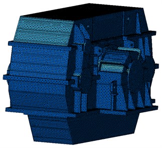
Fig. 9The acoustics boundary element model of marine gearbox
4.2. Acoustic analysis result
Before the calculation of the acoustic characteristic, the proprieties of the acoustic field could be defined as follows: the air density is 1.225 kg/m3; the sound velocity in the air is 340 m/s; the reference sound pressure is 2×10⁻⁵ Pa. The calculation frequency range from 62.5 Hz to 4000 Hz is set according to the octave frequency.
The coupling acoustic boundary element method is adopted to solve the surface sound pressure of the marine gearbox under different frequency range. The surface sound pressure for the frequency 500 Hz is only given because of the limit of space, as shown in Fig. 10.
Fig. 10The surface sound pressure contour of housing
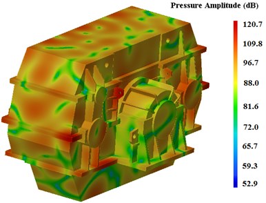
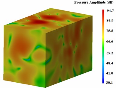
Fig. 11The sound pressure contour of outer field points of housing
From the above figure, we could see that the figure gives an overview of the noise pressure distributions on the surface of gearbox; the maximum value of surface sound pressure of this marine gearbox is 120.7 dB(A) and it occurred at the positions of the bearing seat and the ribbed slab of the upper box.
The radiate noise of the marine gearbox can be got through the calculation of the outer acoustic field points. The radiate noise of the marine gearbox for the frequency 500 Hz is only given, as shown in Fig. 11. The maximum value of radiate noise is 94.7 dB(A).
Fig. 12 shows the distribute diagram of radiation noise computing points which are also the test positions.
The noise pressure curves of field points are shown in Fig. 13. From the figures, we could see that the noise pressure peak occurs at 500 Hz or 1000 Hz; the maximum values are 93.8 dB(A) which appears at field point 2 at the 500 Hz.
Fig. 12The computing positions of filed points of marine gearbox
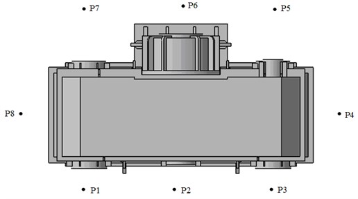
Fig. 13Computational results of sound pressure
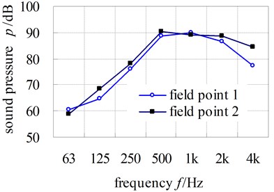
a) Filed point 1-2
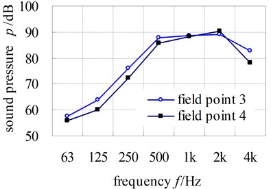
b) Filed point 3-4
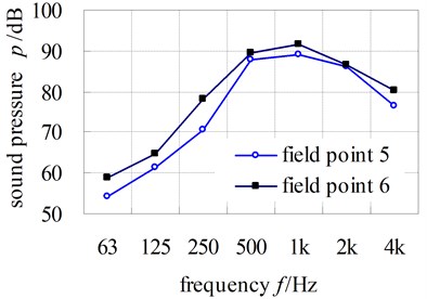
c) Filed point 5-6
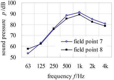
d) Filed point 7-8
4.3. Radiation noise test of experimental prototype
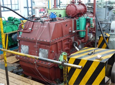
Fig. 14 and Fig. 15 shows the block-diagram of the radiate noise measurement system and the test site of experimental prototype, respectively.
Fig. 14Block-diagram of the radiated noise measurement system
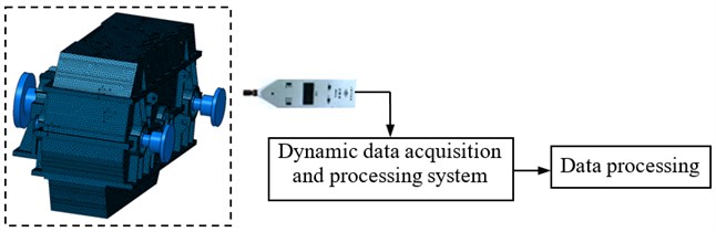
Fig. 15The test site of radiation noise of marine gearbox
The 1/1 octave sound pressure of each measurement point under the experiment condition is tested by the sound meter, which the distance between the measurement point and the measurement surface of marine gearbox is 1 m. The tested radiation noise values of the eight test points around the housing are shown in Table 1.
Table 1The comparison between computational results and test results of sound pressure
Field points | 1 | 2 | 3 | 4 | 5 | 6 | 7 | 8 | Average | |
Logarithm average of the frequency band sound pressure / dB | Calculation value | 85.1 | 86.3 | 85.4 | 85.1 | 84.3 | 86.3 | 85.5 | 83.1 | 85.2 |
Tested value | 86.6 | 89.6 | 87.4 | 86.2 | 84.4 | 88 | 87.3 | 86.3 | 87.2 | |
Relative error / % | 1.7 | 3.7 | 2.3 | 1.3 | 0.1 | 1.9 | 2.1 | 3.7 | 2.3 | |
Total sound pressure level / dB | Calculation value | 93.6 | 94.7 | 93.8 | 93.6 | 92.8 | 94.7 | 93.9 | 91.6 | 93.7 |
Tested value | 95.1 | 98.1 | 95.8 | 94.7 | 92.7 | 96.4 | 95.8 | 94.7 | 95.7 | |
Relative error | 1.6 | 3.5 | 2.1 | 1.2 | 0.1 | 1.8 | 2.0 | 3.3 | 2.1 | |
From the table, the maximum total sound pressure level error of the 8 filed points is 3.5 % and the relative error of the average value of the total sound pressure level is 2.1 %.
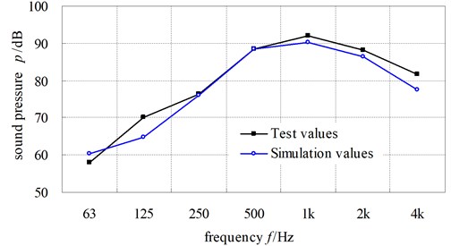
Fig. 16 shows the tested 1/1 octave radiate noise sound pressure spectrum of test point 1. Fig. 17 describes the comparison curves of simulation result with the test result of the radiate noise of field point 1.
It can be apparently seen from result that the rule of both curve is basic similar, but the predicting noise pressure level is different with the test results for some frequency ranges. The reason is likely to be that the engine mechanical vibration effect which is dominant at the lower frequencies and some high frequency errors have not been taken into account in the marine gear system. If all the factors which would affect the vibration of the gear system could be considered in the further study, such as the machining error, assembly errors, the computational simulation would greatly interpret the peak value in the experimental measurement result.
Fig. 16The tested sound pressure spectrum of radiation noise of filed point 1
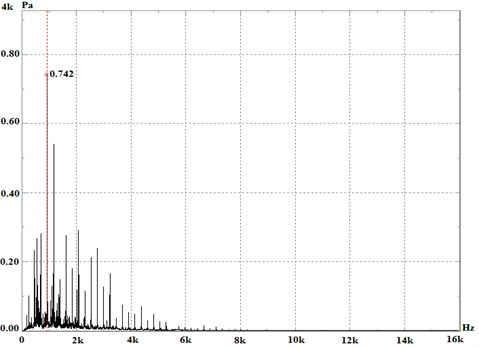
Fig. 17The comparison curves of simulation result and test result of radiation noise of filed point 1
5. Conclusions
1) Taking account of the internal excitations such as the time-varying mesh stiffness, tooth backlash and bearing stiffness and the external torque and speed excitation, the rigid-flexible coupling multi-body dynamic model which contains the structure system and transmission system of gear device is developed to solve the dynamic reaction force of bearings.
2) Taking the dynamic reaction force as the boundary condition of the radiation noise analysis, the vibro-acoustic coupling model of the gear system is established to calculate the surface sound pressure of gearbox and the radiation noise of outer sound field. The results of radiation noise pressure for field points of marine gearbox show that the noise pressure peak point occur at 500 Hz and the maximum value is 93.8 dB(A).
3) Although minute discrepancy of predicting results and test values exists, the difference between predicted and measured radiation noise levels is acceptable. In spite of this, it is possible to confirm that the proposed analysis models for predicting the exterior noise level of gear system are a reliable approach and it can provide us a quick approach of noise prediction in the design process.
References
-
Greenwood J. A., Williamson J. B. P. Contact of nominally flat surfaces. Proceedings of the Royal Society of London, Series A, Vol. 295, 1966, p. 300-319.
-
Smith J. D. Transmission of smith shocks through rolling bearings. Journal of Sound and Vibration, Vol. 181, Issue 1, 1995, p. 1-6.
-
Tian J. Y., Ogi H., Hirao M. Dynamic-contact stiffness at the interface between a vibrating rigid sphere and a semi-infinite viscoelastic solid. IEEE Transactions on Ultrasonics, Ferroelectrics, and Frequency Control, Vol. 51, Issue 11, 2004, p. 1557-1563.
-
Le Moyne S., Tebec J. L. Ribs effects in acoustic radiation of a gearbox-their modeling in a boundary element method. Applied Acoustics, Vol. 63, Issue 2, 2002, p. 223-233.
-
Abbes S. M., Bouaziz S., Chaari F., et al. An acoustic-structural interaction modeling for the evaluation of a gearbox radiated noise. International Journal of Mechanical Sciences, Vol. 50, Issue 3, 2008, p. 569-577.
-
Barthod M., Hayne B., Tébec J. L., et al. Experimental study of dynamic and noise produced by a gearing excited by a multi-harmonic excitation. Applied Acoustics, Vol. 68, Issue 9, 2007, p. 982-1002.
-
Long L., Hongyun L., Dayue Ch. Calculation and analysis of vibration and noise of subway gearbox. Chinese Noise and Vibration Control, Vol. 27, Issue 2, 2007, p. 37-39.
-
Tengjiao L., Lingkuan M., Zeyin H. Dynamic characteristics analysis and radiation noise prediction of spiral bevel gearbox. Chinese Journal of Mechanical Science and Technology, Vol. 32, Issue 3, 2013, p. 319-323.
-
Bindi Y., Jianmin W., Yang Zh. Nonlinear analysis and vibration suppression control for a rigid-flexible coupling satellite antenna system composed of laminated shell reflector. Acta Astronautica, Vol. 96, Issue 2, 2014, p. 269-279.
-
Qiang T., Yanlei S., Cheng L., et al. ElastoHydroDynamic lubricated cylindrical joints for rigid-flexible multibody dynamics. Computers and Structures, Vols. 114-115, 2013, p. 106-120.
-
Zhanfang L., Pei Y., Xiaowei G., et al. Rigid-flexible coupling dynamic analysis on a mass attached to a rotating flexible rod. Applied Mathematical Modelling, Vol. 38, Issues 21-22, 2014, p. 4985-4994.
-
Liu J. Y., Hong J. Z. Geometric stiffening effect on rigid-flexible coupling dynamics of an elastic beam. Journal of Sound and Vibration, Vol. 278, Issues 4-5, 2004, p. 1147-1162.
About this article
The authors are grateful for the financial support provided by Start-up Funding Scientific Research Project of Chongqing Jiaotong University under Contract No. 15JDKJC-B017, National Natural Science Foundation of China under Contract No. 51375519 and 51405048, National Science and Technology Support Project under Contract No. 2015BAF06B02, Natural Science Fund Project of Chongqing under Contract No. cstc2015jcyjA70012, Project Foundation of Municipal Education Committee of Chongqing under Contract No. KJ1500516, National Engineering Laboratory for Highway Maintenance Equipment under Contract No. 310825161104. CN Gpower Gearbox Co., Ltd., is thanked for providing the test site of gearbox.
