Abstract
This paper deals with numerical investigation of the single–stage gearbox housing dynamic behaviour during low-torque operating conditions. First the modal properties of the key components are derived and experimentally evaluated on the physical model. Next the main simulations are performed in MBS (multi-body system) software, the model is based on the open loop test rig. The computational methods aim to represent dynamic behaviour of the gearbox housing key parts with respect to NVH parameters evaluation, which is done by surface normal velocity amplitude. The presented part of investigation also deals with different kind of input speed variability. The simulation results show that the variable input speed has strong influence on dynamic behaviour.
1. Introduction
Transmission systems are one of the most used machinery mechanisms. Most people are directly or indirectly affected by mechanical or acoustic behaviour of this mechanism in everyday life. For each manufacturer, it is crucial to design and then manufacture the transmission, which should meet current limits of whole final product thus be competitive on the market. The understanding of the gear mesh dynamics is key to design the components meeting required noise and vibration limits. Manufacturing of whole transmission and its experimental testing is expensive in terms of both time and material costs, which also significantly affects the final product price. The computational approach is another way how to perform optimization of transmission without manufacturing physical prototypes.
The research of the gear systems is very spread with a focus on the description of the dynamic behaviour. The investigation is mainly performed on the single stage gearbox with simplified housing [1]. The main excitation is caused by time – varying gear mesh stiffness [2]. The aim of the gear manufacturer is teeth optimization to reach smooth gear mesh stiffness.
2. Methods
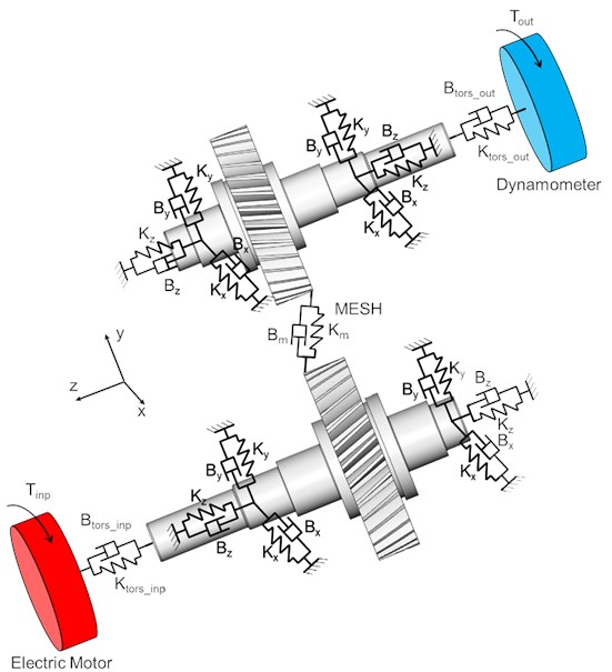
With increasing performance of computer technologies, the numerical simulation enables to provide sensitive study to deep understand dynamic behaviour of gear. For that reason, it is widely used in research and developing phase [3]. The presented virtual prototype is based on dynamic model of transmission with multiple degree of freedom, which is represented in the Fig. 1.
This model incorporates influence of the key components modal properties, the gear mesh stiffness, which is expressed as time – varying function. Further the elasticity of the bearings and couplings is considered. The equation of motion of a dynamic system is based on Newton – Lagrange method and can be symbolically written by Eq. (1):
where is the generalized mass matrix, which is in Eq. (1) related to kinetic energy. is generalized stiffness matrix, related to potential energy and damping matrix is related to Rayleigh’s dissipative function. Generalized gravitational force is presented by , vector stands for generalized coordinates, is vector of forces and represents Lagrange’s multipliers.
Fig. 1A schematic diagram of MDOF virtual prototype
This paper combines finite element method (FEM) utilization, which is used for getting input parameters, and multibody software ADAMS for the main simulation in time domain. Whole methodology is validated by technical experiment, the gearbox parameters and process of verification are described in [4]. The main virtual prototype is built in MBS by using command code which is open. It allows to include and simple change all substantial parameters for different transmission. All the upper mentioned incorporated transmission parameters can be easily modified, including settlement of boundary conditions such as variable input speed and torque.
The FEM is used to calculate the bearing stiffness on one rolling segment and afterwards converted to the whole bearing, which is used as input in ADAMS. This approach is also used in another research studies [5]. The gear mesh stiffness is very important to get real dynamic behaviour of transmission. To get gear mesh stiffness, the parametrical FE model is used. The gear tooth real geometry is discretized with focus on fine mesh on four teeth gear pairs. The stiffness is calculated during the contact of one tooth angle period and afterwards used periodically. No misalignment and manufacture error are presented. The stiffness corresponds to the results mentioned in [6].
In presented paper, the focus is applied on backlash influence, which is incorporated by stiffness – based function with dependency on gear mesh deformation in torsional direction, which is stated by angular displacement of both gears. The function for specific load is mentioned in [7]. Backlash has a significant influence on the dynamic of transmissions due to nonlinear behaviour. Because of this phenomenon the gear mesh contact can be in some certain states released periodically, which is accompanied by impact forces. These critical states can occur, for example, at a low level of carried torques. These impact forces are transferred through the structures of gears, shafts and bearings to the gearbox housing. Because of wide - frequency range excitation character of impact forces the critical eigen mode vibrations states of the key components can occur. Regarding NVH problematic the top lid cover is stated as the main component, where it will manifest itself. It is because of relatively low thickness comparing to another components.
3. Results
In order to describe vibration properties and identify the critical areas of this potentially critical part of gearbox housing, the numerical and experimental modal analysis has been performed. Results in frequency range 600-1500 Hz are shown in the Fig. 2.
Fig. 2Modal analysis results including description of the critical points
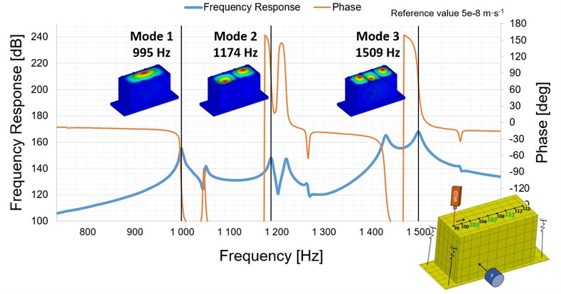
Based on the modal analysis results in defined frequency range three critical areas are determined, which are represented by three points located at each local maximum. If the structure is during operating conditions excited by frequency, which is close to one of the eigen frequencies, resonance of the top lid cover parts can occur. This phenomenon relates to the emission of noise. In this article, the noise level is represented by surface normal velocity level, stated in three local maximum points.
The main numerical simulation on virtual prototype is set to describe dynamic behaviour of the top lid cover during low carried torque conditions. The rotational speed of input shaft has a constant value 2159 RPM and represents the designed intention, which is related to combustion engine. Therefore, the speed variability based on functional principle of combustion engine through the higher harmonics is applied, which corresponds to the article [8]. Load is applied to the output shaft and the value of torque has transient character based on increasing and decreasing phase. Torque is applied in range 0-20 Nm, which represents very low load operating conditions, but during work process of the gearbox it can occur very easily.
The gear mesh contact behaviour is presented by gear mesh angular deformation, which is stated by angular displacement of both gears. This value helps to predict tooth contact releasing due to the combination low carried torque and irregularity of the input speed. In critical phases, the tooth contact releasing can reach such a state that the negative tooth contact can occur. This phenomenon is known as rattle. Both upper mentioned situations are shown in the Fig. 3.
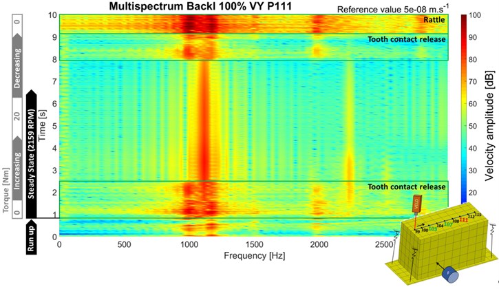
The surface normal velocity of the top lid cover points 107 and 111 is mentioned in the Fig. 4 and Fig. 5. On both figures, there is possible to detect wide frequency range of the local increase of the surface normal velocity amplitude during the release of the contact as well as the rattle phenomenon.
Fig. 3Gear mesh angular deformation
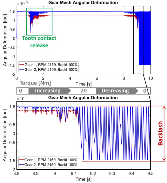
Fig. 4Surface normal velocity point 107
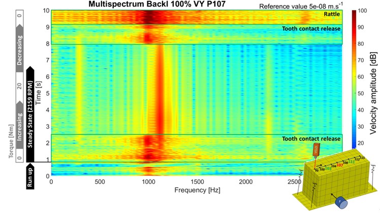
Fig. 5Surface normal velocity point 111
4. Conclusions
Presented methodology, based on the combination of FEM and MBS, was developed on the single stage gearbox. The simple modifiability for use on a wide range of gearboxes was due to open command code. It enabled performing sensitivity analyses of a wide range of parameters. Presented analysis was focused on the effect of low-torque operating conditions, which can easily occur in the real situation. The course of angular deformation, and surface normal velocity was used for evaluation.
The teeth contact loosening, which was connected to the rattle, was presented during steady state rotational speed application, the amplitude of surface normal velocity was affected by level of loading torque. To be close to real operating conditions, the variability of the input speed was applied.
References
-
Tuma J. Vehicle Gearbox Noise and Vibration: Measurement, Signal Analysis, Signal Processing and Noise Reduction Measures. John Wiley, Chichester, 2014, p. 243.
-
Zhan J., Fard M., Jazar R. A CAD-FEM-QSA integration technique for determining the time-varying meshing stiffness of gear pairs. Measurement, Vol. 100, 2017, p. 139-149.
-
Kumar A., Jaiswal H., Jain R., Patil P. P. Free vibration and material mechanical properties influence based frequency and mode shape analysis of transmission gearbox. Procedia Engineering, Vol. 97, 2014, p. 1097-1106.
-
Prokop A., Rehak K., Zubik M., Novotny P. Experimental validation of the gearbox NVH parameters. Journal of Middle European Construction and Design of Cars, Vol. 13, Issue 2, 2015, p. 16-21.
-
Atanasovska I. The mathematical phenomenological mapping in non-linear dynamics of spur gear pair and radial ball bearing due to the variable stiffness. International Journal of Non-Linear Mechanics, Vol. 73, 2015, p. 114-120.
-
Kiekbusch T., Sappok D., Sauer B., Howard I. Calculation of the combined torsional mesh stiffness of spur gears with two- and three-dimensional parametrical FE models. Strojniski Vestnik, Journal of Mechanical Engineering, Vol. 57, Issue 11, 2011, p. 810-818.
-
Řehák K., Prokop A. Numerical simulation of single stage gearbox with tooth damage. Vibroengineering Procedia, Vol. 7, 2016, p. 88‑92.
-
Drápal L., Šopík L., Vopařil J. Investigation of torsional vibration of unconventional crank train. Vibroengineering Procedia, Vol. 7, 2016, p. 31-36.
About this article

The research leading to these results has received funding from the Ministry of Education, Youth and Sports under the National Sustainability Programme I. (Project LO1202) and with help of the Project FSI-S-17-4104 granted by specific university research of Brno University of Technology. The authors gratefully acknowledge this support.
