Abstract
This study analyzes torque oscillation characteristics in the process of bobbin tool friction stir welding. The empiral data of torque, the point temperature of contact surface and the leading point temperature is presented to explore the torque signal spectrum characteristics, the causes of the periodic oscillation of torque, the relationship between the oscillation and the surface forming of weld joint. The result shows that the torque in BTFSW has regular oscillation. The oscillation frequency of the torque is nearly 2 times the spindle frequency. With the increase of rotary speed, the oscillation frequency and the frequency difference increase gradually. There is no significant linear relationship between the amplitude peak of the torque, traveling speed, rotary speed and the measured point temperature. The instable temperature of the leading areas to be welded inevitably leads to the instability of the torque amplitude. The analysis indicates that the more intense of the heat input rate, the more obvious of the torque vibration, and the small and uniform torque amplitude does not affect the surface shape. Once the oscillation is abnormal, it easily leads to the poor surface forming and the hole defect.
1. Introduction
Bobbin tool friction stir welding (BTFSW) is a new derivative technology of friction stir welding, by which material is joined through mechanical stirring via a rotating tool that traverses the joint line [1]. Compared with conventional FSW, the bobbin tool consists of a pin and two shoulders; BTFSW is effective for joining hollow extrusions and lap joints.
Like conventional FSW, there is no linear relationship among welding process parameters, such as the rotary speed, traveling speed, torque and forward resistance; but they influence one another. Lafly et al. pointed out that welding parameters of FSW and BTFSW have the same impact on welding quality [2] and BTFSW can even weld the sheet [3]. During the BTFSW welding process, high speed rotating tool causes high temperature in weld area, which leads to plastic deformation and migration of metal between two shoulders. Some studies have focused on the microstructure analysis [4-8]. For example, Thomas put forward that tapered pin can reduce welding torque and forward resistance, which can protect the pin, but not for BTFSW welding [9]. In other studies about the shoulder, the concave shoulder is used more, but convex shoulder has more application flexibility [10-12]. The shoulder with spiral groove enables the metal flow toward welding center, which is conducive to welding [13]. Scialpi pointed out that stirring pin with a combination of thread features and platforms is more conducive to welding, but it does not mean that the more the platform is, the better its effects will be, and optimum number should be no more than 4 [14].
In conventional FSW, the torque affects the stability of the welding process [15], rheology state of welding region metal [16], and may also be related to welding defects [17]. Torque has close relationship with the temperature of work-piece [18], showing cyclical changes [19-20]. Yan et al. illustrated that the interaction between rotating pin and plastic metal results in periodic response through a comparative study between different welding parameters and tool deflection [21]. Zhang et al. proposed that torque and pressure changes periodically, and the cycle is consistent with the period of rotation according to the simulation FSW test [22]. Torque decreases with the increase of the rotary speed while the torque increases with the increase of traveling speed [23].
Different from the conventional FSW, bobbin tool has larger pin and shoulder, it can produce heat on both sides of the plate simultaneously. Due to the special nature of BTFSW, characteristics of the torque are correspondingly different with FSW, which inevitably have an impact on the joint organization and performance. However, there is a lack of description about BTFSW torque features in the current studies. Therefore, it is necessary to conduct further research.
The purpose of this research is to explore the torque oscillation phenomenon and its relationship with weld forming during the BTFSW process. The zero degree tilting angle is utilized to the welding tool for all the trails. The interest is in periodic oscillation perspective, rather than simply a description of steady welding torque. This paper specifically probes into the relation between the oscillation cycle and the process parameters, with a particular focus on the poor weld surface forming.
2. Torque oscillation of BTFSW
As shown in Fig. 1(a), the rotary tool crashes into welding seam with lower traveling speed, and then a solid-state weld is formed by the friction and extrusion of the tool. In this study, the size of 6061 aluminum plate is 230 mm×80 mm×6 mm. During the friction stir welding process, welding torque comes from two parts: sliding friction and viscous friction. Although sliding friction is the main part, the proportion of viscous friction increases gradually as temperature increases when the welding zone is in high temperature (above 560 K) [22]. As described in Eqs. (1) and (2), constitutive equations of 6061 aluminum are in line with the inverse hyperbolic sine function, viscosity stress may be expressed as:
where is welding temperature (K) and is strain (s-1). , , , are material constants [24] (0.06 MPa-1, 6.966, 4.6867E9 s-1, 276.8 KJ/mol); is the equivalent to the steady state flow stress (MPa), is the gas constant ( 8.314 mol-1 K-1), and is Zener-Hollomon parameter. When the welding zone temperature changes within 560 K-860 K and effective strain within 0.1-100 s-1, changes as shown in Fig. 1.
Fig. 1Schematic diagram of BTFSW
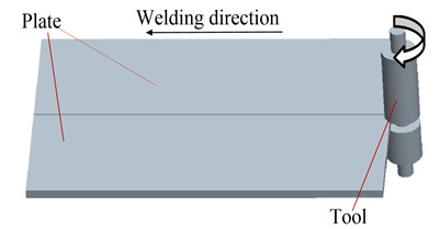
Fig. 2Viscosity stress surface
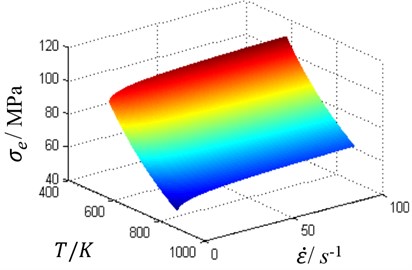
Obviously, is influenced by welding zone temperature and strain . Due to the high efficiency of sliding friction, welding zone metal is quickly softened to a plastic state. After the plastic metal is removed by moving and rotating tool quickly, the lower temperature metal ahead of tool becomes new extrusion and friction zone rapidly, leading to dramatic changes of viscous friction stress in temperature and effective strain. The above-described process could create a cycle, and then lead to torque oscillation. In the actual welding process, it is difficult to detect , thus torque changes cannot be calculated theoretically. Therefore, this article intends to use sensors to detect the output torque of the spindle, analyzing BTFSW torque oscillations.
3. Test apparatus and method
As shown in Fig. 3(a), the experiment is conducted on a modified milling machine which has been retrofitted with more advanced motors and instrumentation. The spindle is driven by a asynchronous spindle motor with 15 KW, with spindle speed range of 0-5000 RPM. Through the welding equipment, welding process data can be collected with sampling frequency 500 Hz. The process data includes: traveling speed (), rotary speed (), welding torque (), forward resistance (), the point temperature of the top shoulder/work-piece interface (T1), the point temperature of leading surface (T2). The leading surface refers to the area to be welded in front of welding tool, and the position of T2 is 23 mm in front of tool center. The diameter of the shoulders is both 23 mm, and the pin diameter is 9 mm. There are two symmetrical threads and three platforms on the pin surface, as shown in Fig. 2(b). For each welding test, the rotary speed remains unchanged while traveling speed sequentially varies within certain range (10 mm/min-170 mm/min), then followed by a constant traveling speed for subsequent welding process. After welding, all welds are visually inspected for identifying defects such as flash and surface flaws, then torque oscillation characteristics is analyzed.
Fig. 3Welding equipments
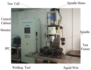
a) BTFSW machine
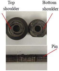
b) Shoulder and scrolled pin
4. Results and discussion
4.1. Welding torque waveform change
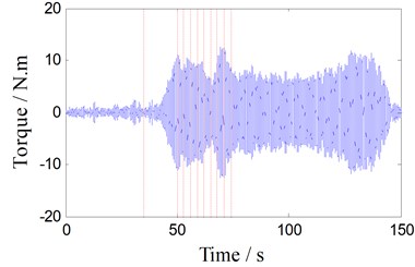
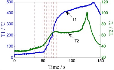
BTFSW welding process parameters is shown in Fig. 4 when the rotary speed is 350 rpm. The staircase curve shown in Fig. 4(a) is traveling speed, and the variety sequence of traveling speed (unit: mm/min) is: 10, 20, 30, 50, 70, 90, 110, 130, 150, 170; dwell time (s) of each speed is: 35, 15, 3, 3, 3, 3, 3, 3, 3, 3, as the dotted lines shown in Fig. 4(a)-(d). Fig. 4(b) shows the unfiltered torque signal, Fig. 4(c) is filtered torque signals using Butterworth low-pass filter (cut-off frequency 3.5 Hz). As shown in Fig. 4(d), T1 is the specific contact point temperature of interface between top shoulder and work-piece, and T2 is one point temperature of the leading surface.
Fig. 4The welding parameter curve (350 RPM)
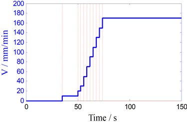
a) The traveling speed curve
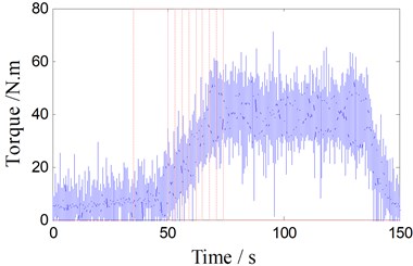
b) The torque signal (unfiltered)
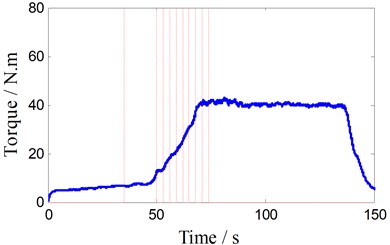
c) The torque signal (without filtered)
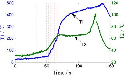
d) T1/T2
As shown in Fig. 4(b), torque signals are mixed with noise and oscillation in the entire welding process, Fig. 4(c) shows the filtered torque signal. When the rotary welding tool extrudes into the workpiece with low traveling speed (10 mm/min), welding torque, T1 and T2 are very small and increase slowly. But after 50 s, they increase significantly as the traveling speed increases 20 mm/min every 3 seconds. After traveling the speed increases to 170 mm/min, T2 and torque also keep steady, but all the while the T1 increases slowly. When the shoulders are close to the edge of the work-piece (120 s), T2 increases rapidly due to heat accumulation, but it decreases quickly after thermocouple leaves early from the work-piece. The welding torque and T1 also gradually decrease to zero when the shoulder leaves from the work-piece.
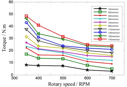
Fig. 5The relationship between the torque and the rotary speed
4.2. The relationship between low-frequency torque and welding parameters
When the rotary speed of welding tool is respectively 350 RPM, 400 RPM, 500 RPM, 600 RPM, 700 RPM, the relationship between steady torque and the welding parameters is shown in Fig. 5. Overall, the torque decreases as the rotary speed increases, but it increases with the increase of the traveling speed.
When the traveling speed is constant, the relationship between the torque and the rotary speed can be expressed as:
here , , are the coefficients of the polynomial. The relations between the traveling speed and , , can be expressed as:
It is worth mentioning that many factors affect the torque. The above parameters of the formula will change by the variety of the workpiece material and its thickness, thermal boundary conditions.
4.3. Characteristics of the torque periodic oscillation
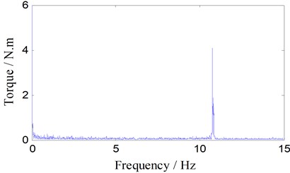
Under the condition of rotary speed (350 RPM, with rotary frequency 5.83 Hz), the result of the FFT (Fast Fourier transform) of the unfiltered torque signal is shown in Fig. 6. From the FFT spectrum of torque, the frequency of the main component is 10.78 Hz.
Fig. 6FFT Spectrum
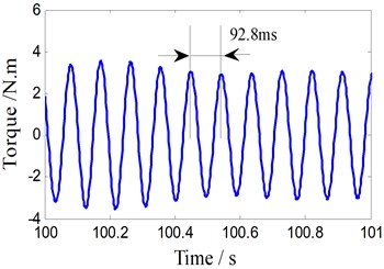
In order to display the oscillation signal of torque, six-order Butterworth digital bandpass filter is carried out on the original torque signal, then the torque periodic signal (near 10.78 Hz) is shown in Fig. 7(a). The filter transfer function is:
The amplification of the oscillation signal during the period of 100 to 101 s is shown in Fig. 7(b), and the oscillation cycle is clearly displayed (92.8 ms).
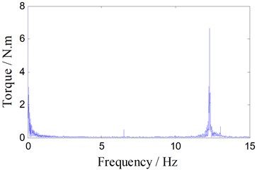
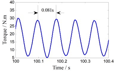
With the same spectrum method, FFT Spectrum of another torque signal (rotary speed is 400 RPM and its frequency is 6.67 Hz) is shown in Fig. 8. The main frequency is 12.34 Hz and the oscillation period is 81 ms obviously.
The similar experiments are conducted subsequently, with rotary speed and rotary frequency of 500 RPM and 8.33 Hz, 600 RPM and 10 Hz, 11.67 RPM and 6.67 Hz, and the main frequency of the output torque is 15.36 Hz, 18.43 Hz and 21.49 Hz, respectively. According to the above analysis, the oscillation frequency of the torque is close to 2 times the spindle frequency. There is a periodic torque during the conventional FSW process, which is similar with the set value of spindle frequency [22]. The following are reasons why our work results are different from conventional.
In the conventional FSW process, the diameter of pin and shoulder is smaller than the BTFSW. Besides, due to the suspended workpieces and small contact radiating area, the heat produced in BTFSW process is much more than that in conventional FSW with the same rotary speed. Under this condition, a welding process cycle is created: the heat accumulation in welding zone causes the welding metal to soften quickly. When the pin touches the low temperature metal, the torque will be larger and more heat is produced, then metal will be softened again. After the soften metal be removed by moving and rotating tool, the pin will touch the low temperature metal ahead of tool, then the torque will increase soon. As more heat is produced in BTFSW, the torque change frequency is higher than conventional FSW. According to the measured data, weld metal has finished the cycle of heating-softening-removing in half of this cycle. In the next half cycle, above process is repeated again. This phenomenon also shows that the heat and transfer ability in BTFSW process is stronger than conventional FSW under the same condition.
Fig. 7Torque oscillation signal (350 RPM)
a) Torque periodic signal
b) Local oscillation signal
Fig. 8Torque signal FFT analysis (400 rpm)
a) FFT spectrum
b) Local signal
4.4. Relationship between the torque oscillation and the welding parameters
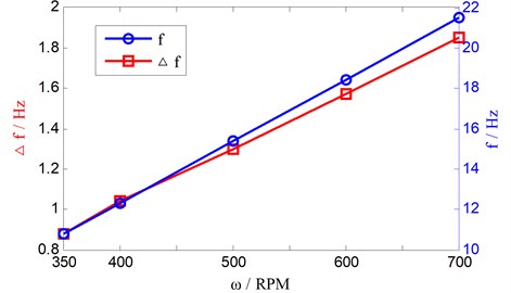
After further analysis of the local torque amplitude waveform, the conclusion can be drawn that the frequency of torque oscillation signal () is independent of the traveling speed. However, what is the relationship between () and rotary speed ()? Then, we define as the difference between oscillation frequency and twice the rotary speed frequency (). As rotary speed increases, the frequency difference () and the oscillation frequency () gradually increase, as shown in Fig. 9.
Furthermore, the relationship between the torque oscillation frequency and the rotary speed is given by:
It can be seen from Fig. 9, more relative rotation appears as rotary speed increases. This shows that the relative compression and sliding friction between welding metal and tool exit in this process, the welding metal has gone through heating-softening-transfer in the half cycle of rotary period.
Fig. 9Oscillation frequency and frequency difference
4.5. Relationship between torque oscillation and welding temperature
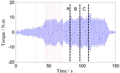
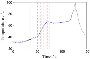
In order to validate the above analysis and reveal the relationship between temperature and torque oscillation amplitude in welding zone, the travel speed is changed to 500 RPM, 3 gaps (width 0.3 mm) perpendicular to the welding direction are placed on the route of tool, as the dotted lines A, B, C shown in Fig. 10(a), when tool passing the gap, a larger torque oscillation appeared. Due to the gaps, heat conduction along the direction of welding is reduced, which make the temperature of both sides along welding direction different. This is reflected in the temperature curve T2, in Fig. 10(b).
As shown in Fig. 4(a), Fig. 10(a), there is no linear relationship between torque oscillation amplitude and traveling speed. Larger amplitude is produced in lower or higher traveling speed. As shown in Fig. 10(a), at rotary speed of 500 RPM, it produces greater amplitude (10 Nm) at a few points, which peaks are similar with amplitude (10 Nm) in 350 RPM. Similarly, Fig. 10(b) shows that the amplitude of torque oscillation and the temperature T1 have no linear relationship, either. Then what is the relationship between amplitude and the point temperature of leading surface (T2)?
In order to further characterize relationships between the torque oscillation characteristics and T2, gauss wavelet transformation method that can effectively smooth the raw data is adopted. The singular points of leading point temperature change can be extracted by using the first derivative extract. The core algorithm of convolution type wavelet transform is shown as:
where is the stretch of the scale factor . When 1, the first derivative of leading point temperature is shown in Fig. 10(c).
When the first derivative of T2 approaches to 0, it can be considered that a stable temperature distribution of leading surface is forming; theoretical analysis shows that the first derivative of local minima is corresponding to mutation point of the original signal edge. According to Fig. 10, in fact, large amplitude oscillation of torque has appeared before the temperature of leading surface changes, this suggests that the oscillation amplitude increases earlier than peak moment of the first derivative of T2. This phenomenon is caused by delay of heat transfer. A further analysis indicates that the first derivative of T2 reflects the heat input rate. The more intense the heat input rate changes, the more obviously the torque oscillates. From the above analysis, the temperature of the metal in front of tool and its changing rate indirectly illustrate that unstable temperature of zone to be welded inevitably leads to instability of torque oscillation amplitude.
It can be seen that dynamic control of leading welding temperature is necessary, asking for further research of methods used to control leading point temperature. It will be of utmost significance to the control of welding process stability and welding quality.
Fig. 10Oscillating torque and contact point temperature, the leading point temperature (500 RPM)
a) Torque oscillations
b) T1 and T2
c) Change rate of T2
4.6. Abnormal torque oscillations and the weld surface forming
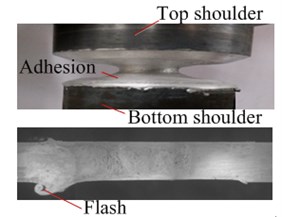
Experimental data shows that there is a direct relationship between the torque oscillation amplitude and the weld surface forming. When the oscillation amplitude is small (less than 10), the surface is bright and clean and the flash is smaller; while the T1 is higher than 550 °C and oscillation amplitude is bigger (greater than 10), abnormal high frequency oscillation appears, which leads to serious flash. When this phenomenon occurs, the plasticized metal is adhered to shoulders and pin (Fig. 11(a)). The test results show that as long as the adhesion phenomenon occurs, the weld surface molding will deteriorate to be a serious flash, weld joint thickness reducing (Fig. 11(a)).
The causes of abnormal oscillation phenomenon are: unreasonable vertical distance between the shoulders, improper traveling speed, too large rotation speed, etc. When the vertical distance of two shoulders and traveling speed are too small, heat input and forward resistance will increase. When the temperature of the welding area is close to the melting point of the base metal, excessive softening of material tends to adhere to shoulders and pin. This leads to thinner weld, larger pin diameter and welding torque. The increasing torque leads to more heat input, higher welding temperature, thus increasing torque oscillation amplitude. Such a vicious cycle results in worse and worse surface forming, and more serious flash. While the distance is too large and the traveling speed is too fast, heat input deficiency can cause low frequency oscillation torque. At this point, oscillation will be dangerous and easily lead to pin breakage. Fig. 11 shows the torque and forward force oscillation waveform caused by the lack of heat input under a rotary speed (340 rpm) and traveling speed (180 mm/min), in which the pin broke and welding interrupted at 103 s.
Fig. 11Welding parameters abnormal low frequency oscillation
a) Adhesion and flash phenomenon
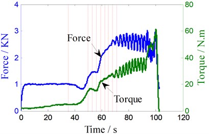
b) The torque and forward resistance curve
5. Conclusions
When the contact point temperature of top work-piece BTFSW is less than 500 °C, the low frequency torque and steady-state will increase with the increase of the traveling speed, but it will decrease with the increase of the rotating speed. When the welding tool runs at constant welding parameters, in the middle and later process, the torque will decrease and amplitude will become large due to the accumulation of heat.
The phenomenon that the torque oscillation and its unstable amplitude is throughout the entire process of BTFSW. In addition, the main frequency of oscillation signal is close to two times of the spindle frequency, independent of the traveling speed. With the increase of the rotary speed, the oscillation frequency and the frequency difference gradually increase. The metal of welding zone is in the cycle of rapid heating-softening-transfer.
There is no linear relationship among oscillation amplitude, the traveling speed, rotary speed of welding tool, and the point temperature of leading surface. The unstable temperature of area to be welded inevitably causes the unstable oscillation amplitude of torque. The greater change rate of the heat input, the more obviously torque oscillates. The small and regular torque amplitude can’t affect the surface forming. When torque is in the state of abnormally high-frequency oscillation, deterioration of surface forming is easily caused. The torque of low-frequency oscillation leads to the breakage of pin, which directly leads to welding failure.
References
-
Dong J. H., Nie X. S., Yan J. W., et al. The effect of aluminum alloy microstructure and property by conventional FSW and BTFSW. Welding Institution, Vol. 34, Issue 7, 2013, p. 85-86.
-
Lafly A. L., Allehaux D., Marie F., et al. Impact of friction stir welding techniques on microstructure changes and mechanical properties. Welding in the World-London, Vol. 49, Issue 1, 2005, p. 444.
-
Neumann T., Zettler R., Vilaca P., et al. Analysis of self reacting friction stir welds in a 2024-T351 alloy. Friction Stir Weld Process IV, A Publication of TMS, 2007, p. 55-72.
-
Woo W., Balogh L., Ungár T., et al. Grain structure and dislocation density measurements in a friction stir welded aluminum alloy using X-ray peak profile analysis. Materials Science and Engineering: A, Vol. 498, Issues 1-2, 2008, p. 308-313.
-
Suhuddin U., Mironov S., Sato Y.S., et al. Grain structure and texture evolution during friction stir welding of thin 6016 aluminum alloy sheets. Materials Science and Engineering: A, Vol. 527, Issues 7-8, 2010, p. 1962-1969.
-
Rajakumar S., Muralidharan C., Balasubramanian V. Statistical analysis to predict grain size and hardness of the weld nugget of friction-stir-welded AA6061-T6 aluminum alloy joints. The International Journal of Advanced Manufacturing Technology, Vol. 57, Issues 1-4, 2011, p. 151-165.
-
Chen H. B., Yan K., Lin T., et al. The investigation of typical welding defects for 5456 aluminum alloy friction stir welds. Materials Science and Engineering: A, Vol. 433, Issues 1-2, 2006, p. 64-69.
-
Zhang H., Wang M., Zhang X., et al. Microstructural characteristics and mechanical properties of bobbin tool friction stir welded 2A14-T6 aluminum alloy. Materials and Design, Vol. 65, 2015, p. 559-566.
-
Thomas W. M., Wiesner C. S., Marks D. J., et al. Conventional and bobbin friction stir welding of 12% chromium alloy steel using composite refractory tool materials. Science and Technology of Welding and Joining, Vol. 14, Issue 3, 2009, p. 247-253.
-
Cederqvist L., Sorensen C. D., Reynolds A. P., et al. Improved process stability during friction stir welding of 5 cm thick copper canisters through shoulder geometry and parameter studies. Science and Technology of Welding and Joining, Vol. 14, Issue 2, 2009, p. 178-184.
-
Aval H. J., Serajzadeh S., Kokabi A. H. The influence of tool geometry on the thermo-mechanical and microstructural behaviour in friction stir welding of AA5086. Proceedings of the Institution of Mechanical Engineers, Part C: Journal of Mechanical Engineering Science, Vol. 225, Issue 1, 2011, p. 1-16.
-
Leal R. M., Leitao C., Loureiro A., et al. Material flow in heterogeneous friction stir welding of thin aluminium sheets: effect of shoulder geometry. Materials Science and Engineering: A, Vol. 498, Issue 1, 2008, p. 384-391.
-
Scialpi A., DeFilippis L. A. C., Cavaliere P. Influence of shoulder geometry on microstructure and mechanical properties of friction stir welded 6082 aluminum alloy. Materials and Design, Vol. 28, Issue 4, 2007, p. 1124-1129.
-
Sued M. K., Pons D., Lavroff J., et al. Design features for bobbin friction stir welding tools: development of a conceptual model linking the underlying physics to the production process. Materials and Design, Vol. 54, 2014, p. 632-643.
-
Longhurst W. R, Strauss A. M, Cook G. E., et al. Torque control of friction stir welding for manufacturing and automation. The International Journal of Advanced Manufacturing Technology, Vol. 51, Issues 9-12, 2010, p. 905-913.
-
Shneider J. A. Temperature distribution and resulting metal flow. Friction Stir Welding and Processing, Vol. 3, 2007, p. 37-50.
-
Kim Y. G., Fujii H., Tsumaura T., et al. Three defect types in friction stir welding of aluminum die casting alloy. Materials Science and Engineering: A, Vol. 415, Issue 1, 2006, p. 250-254.
-
Cui S., Chen Z. W., Robson J. D. A model relating tool and its associated power and specific energy to rotation and forward speeds during friction stir welding/processing. International Journal of Machine Tools and Manufacture, Vol. 50, Issue 12, 2010, p. 1024-1030.
-
Balasubranmanian N., Mishra R. S., Krishnamurthy K. Process forces during friction stir channeling in an aluminum alloy. Journal of Materials Processing Technology, Vol. 211, Issue 2, 2011, p. 305-311.
-
Qian J. W.,Li J. L., Xiong J. T., et al. Periodic variation of torque and its relations to interfacial sticking and slip-ping during friction stir welding. Science and Technology of welding and Joining, Vol. 17, Issue 4, 2012, p. 338-341.
-
Yan J. H., Sutton M. A., Reynolds A. P. Processing and banding in AA2524 and AA2024 friction stir welding. Science and Technology of Welding and Joining, Vol. 12, Issue 5, 2007, p. 390-401.
-
Zhang X. C., Xiong J. T., Li J. L., et al. Metal mechanics parameters cycle responsive behavior on constant feed rotary friction condition. Journal of Machinery Engineering, Vol. 51, Issue 2, 2014, p. 65-70.
-
Yan D. Y., Shi Q. Y., Wu A. P., et al. Experimental measurement and analysis on friction stir welding process. Welding Institution, Vol. 31, Issue 2, 2010, p. 69.
-
Zhao P. F., Ren G. S., Xu C. G., et al. Research on material constant values of 6061 Aluminum alloy. Journal of Plasticity Engineering, Vol. 13, Issue 4, 2006, p. 79-81.
About this article
This research was supported by the National Natural Science Foundation of China (51205175, 51375218) and the Project Funded by Key Discipline Construction of Jiangsu Province (SZB20014-37).
Data collection: Shujin Chen, Hao Li and Junrong Xue. Data analysis: Shujin Chen, Hao Li and Junrong Xue. Data interpretation: Shujin Chen, Hao Li and Junrong Xue. Drafting manuscript: Shujin Chen, Mingfang Wu, and Jianghui Dong. Revising manuscript content: Shujin Chen and Jianghui Dong. All authors have read and approved the final submitted manuscript.
