Abstract
The dynamic force of the annular flow with finite axial length on the rotor is investigated in this article. A test rig to study the annular flow is built in the CNC machine tool. The rotor of the test rig is connected with the spindle of the machine tool by flange while the stator is located at the machine table. Between the rotor and stator, there is the annulus which is filled with water. The modal frequencies of the test rig are tested for different axial lengths of the annular flow with hammer impulse excitation. The dynamic fluid-structure model consisting of rotor, annular flow and stator is established by the finite element method. Two-dimensional annular flow model which is based on the Bulk-flow theory is utilized to describe the dynamic force of the annular flow. The added mass, damping and stiffness matrix of the annular flow are generated to represent the transient interaction force of the rotor and stator by the annular flow. To study the 3D effect of the annular flow with short axial length, the modification coefficient of the added mass, damping and stiffness matrix is proposed. When the axial length of the annular flow changes, the variation of the modal frequencies of the test rig predicted by the dynamic fluid-structure model is in good agreement with the experimental results. The modification coefficients are almost linear with the axial length of the annular flow for different average gap thickness. For the annular flow with short axial length, the 3D effect is significant and can’t be ignored. The annular flow force with short axial length may have a positive correlation with the square of the annulus axial length.
1. Introduction
Rotors subjected to annular flows are found in many engineering constructions, particularly in the nuclear canned motor pump of Advanced Passive Pressurized Water Reactor, turbo machinery, hydraulic turbines, aircraft engine [1, 2]. These rotors subjected to fluid-structure interaction may face the flow-induced vibration [3, 4].
The rotor dynamics in a Fluid-filled Annular Region depends largely on physical phenomena taking place in surrounding fluids. The surrounding fluids rotates at certain speed and is also part of the rotating system. However, the motion of the fluids depends on the motion of the shaft and vice versa. In fluid lubricated bearings, in seals and the gap between the rotor core and stator core in the canned motor, the fluids are contained in annular gaps. The fluid flow varies in those gaps ranging from laminar shear flow in hydrodynamic bearings to fully developed turbulent flow in seals and the gaps in the canned motor pump [5].
In the journal bearing, the gap between the rotor and stator are very small. The Reynolds equation derived from the Navier-Stokes equations is used to describe the fluid flow in which the viscous force is dominant. A large amount of research papers have been published in this area, for example in papers by Hamrock [6] and Childs [9]. For the seal, a lot of papers have also been published, such as Flouros M. [7], Du K. Li [8]. The axial length of the journal bearings is small. The leakage of the lubrication at the two axial ends of the journal bearing has great influence on the performance of journal bearings. For the seals, the fluid leakage of the seals also affects the seals’ damping coefficients and stiffness coefficients.
In the gaps which have much bigger gap ratio than that in the journal bearing and the seals, the fluid field is quite different. Fritz [10, 11] performed a bulk-flow analysis of an annular fluid for a long rotor and calculated the rotor dynamic coefficients. The bulk-flow means that the tangential flow velocity profile becomes almost constant over most of the annular gap. By assuming that the rotor was centered in the annulus and that there was no axial flow, Fritz evaluated the rotor dynamic coefficients of a concentric fluid annulus. Antunes J. and Grunenwald T. [12, 13] published a serial of articles about the force effect of the annular flow on the rotor. They developed a theoretical model to predict the dynamic behavior and stability of a rotating shaft immersed in both a concentric or eccentric fluid annulus. Their model accounts for the eccentricity of the rotor as well as the influence of rotor spinning velocity. They concluded that the annulus eccentricity was shown to be a very important parameter. The results were compared and validated by experiments. These linear analyses were almost based on the perturbation method; the nonlinear terms were ignored.
Antunes J. and co-workers [14-16] developed a theoretical model for nonlinear planar motions and orbital rotor motions under fluid confinement using simplified flow equations on the gap-averaged fluctuating quantities. M. Moreira [17, 18] developed an improved linear model for rotors under moderate fluid confinement by utilizing a symbolic-numerical formulation based on a spectral Galerkin approach. In 2003, M. Moreira [19, 20] derived an improved model for the more general case of dissipative linearized motions of an eccentric rotor. Ida Jansson [5] presented a fluid-rotor model that captures the effect of inertia and angular momentum of a fluid annulus on vibrations of an inner rigid cylinder by one single complex equation. Generally speaking, the linear force effect and the nonlinear force effect are all studied by assuming that the length of the annular flow is long enough to ignore the 3D effect at the two axial ends of the annular flow.
When the axial length of the annular flow is relatively short, the 3D effect of the annular flow is significant. The fluid leakage at the axial end of the annulus has significant influence on the pressure field of the annular flow. Sun Qiguo [21] developed a dynamic model for analyzing the dynamic characteristics of 3D large gap annulus based on Hirs’ bulk flow theory and Moody’s fraction factor equation. Based on the 3D mechanical model for a large gap annular flow, Sun Qiguo [22] derived the zero-order perturbation equations of 3D non-linear partial differential equations for the motion of an eccentric rotor in a finite-length large gap annular flow. The 3D effect of the annular with finite length was studied.
In this paper, the dynamic force effect of the annular flow with finite axial length is investigated. A test rig to study the annular flow is built in the CNC machine tool. The rotor of the test rig is fixed to the spindle of the machine tool while the stator is located at the machine table. Between the rotor and stator, there is the big gap annulus which is filled with water. Two-dimensional annular flow model which is based on the Bulk-flow theory is utilized to study the dynamic force of the annular flow. When the axial length of the annular flow is assumed to be infinite, the added mass, damping and stiffness matrix of the annular flow are generated from the two-dimensional annular model to represent the coupling force of the rotor and stator. The dynamic fluid-structure finite element model consisting of rotor, annular flow and stator is established. The modal frequencies of the rotor and stator coupled by the annular flow with different axial lengths are tested by hammer impulse excitation. The modification coefficient of the mass, damping and stiffness matrix is proposed to represent the 3D effect of the annular flow with finite axial length. By adapting the modification coefficient, the modal frequencies of the test rig predicted by the dynamic fluid-structure model are in good agreement with the experimental results for the annular flow with short axial length. The modification coefficient is almost linear with the axial length of the annular flow. For the annular flow with short axial length, the 3D effect has very important effect on the force generated by the annular flow.
2. Test rig of the annular flow
To study the annular flow’s force effect, the DMU Five-axis CNC machine tool is used to build the test rig. Fig. 1(a) is the schematic diagram: 1. Spindle, 2. Cover, 3. Outer shell which is made of plexiglass, 4. Aluminum rotor, 5. The Aluminum base, 6. Displacement transducer, 7. Pressure transducer, 8. Displacement transducer, 9. Flange. Fig. 1(b) is the global view of the test rig. The water is supplied from the water inlet at the bottom of the outer shell by a pipe and is drained out of the annulus from the water outlet at the top of the outer shell. The circulation of the water can prevent the air from entering into the annulus through the seal clearance between the rotor and cover.
Fig. 1Test rig
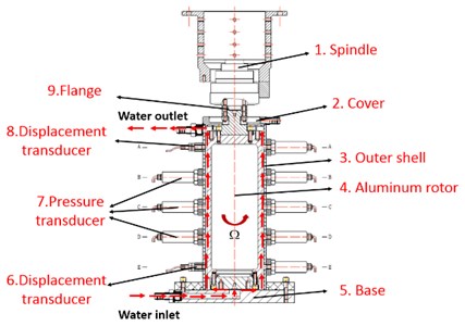
a) Schematic diagram
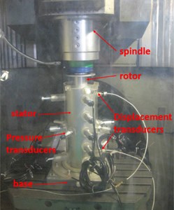
b) Global view of the test rig
The Aluminum rotor is connected with the spindle of the machine tool by the flange. The other end of the rotor is free. The spindle of high-speed CNC machine tool is used to drive the rotor. The spindle speed can be adjusted within 0-8000 rpm continuously. The location of the rotor in the outer shell can be specified by the CNC program accurately. The rotor eccentricity is adjustable. The outer shell is made by plexiglass and fixed on the machine tool tables. The flow field in the annulus can be observed clearly. At the bottom of the outer shell, there are two eddy current displacement transducers in two perpendicular directions to monitor the vibration of the rotor. As shown in Fig. 2, the type of the pressure transducers is ST-00-11-01-10-60-15-02. The sensor’s range is 0-4 mm and the output voltage is 0-10 V.
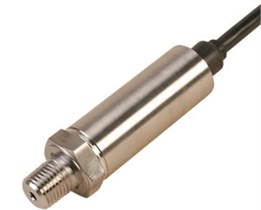
There are twelve pressure transducers at the outer shell evenly. As shown in Fig. 3, the type of the pressure transducer is HM90H1-3-V2-F0-W1. The range is 0-0.4 MPa and the output voltage is 0-5 V. Analogue signals delivered by the transducers are filtered, conditioned, pre-amplified, digitized and recorded before analysis.
Fig. 2Displacement transducer
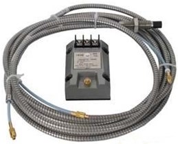
Fig. 3Pressure transducer
The parameters of the test rig are shown in Table 1. There are three kinds of rotors with different radii. So there are three kinds of gaps with different average thickness .
Table 1Parameters of the test rig
Configuration | A | B | C |
Rotor diameter (mm) | 122 | 130 | 134 |
Rotor length (mm) | 365 | 365 | 365 |
Stator inner diameter (mm) | 138 | 138 | 138 |
Gap average thickness (mm) | 8 | 4 | 2 |
3. Modal frequencies of the test rig for different axial length of the annular flow
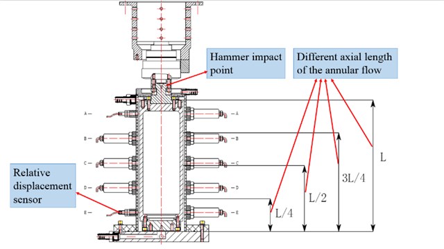
In order to study the influence of the annular flow with different axial length on the rotor’s dynamic characteristics, the test rig’s modal frequencies under different conditions are tested by the hammer impulse method. As shown in Fig. 4, five different axial lengths of the annular flow are chosen which are 0 (dry rotor), , (half wet), , (wet rotor), where is the rotor’s axial length. For each length of the annular flow, use the hammer to impact the rotor and record the free displacement response of the rotor. By utilizing the Fourier transform, the modal frequencies of the test rig are obtained.
Fig. 4Different axial lengths of the annular flow in the experiment
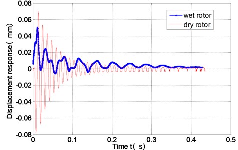
When the gap thickness is 4mm and the rotor spinning velocity is zero, the displacement responses of the dry rotor and the wet rotor under the hammer impact are shown in Fig. 5. When the whole gap is filled with water, the free response of the wet rotor under the hammer impact is quite different from that of the dry rotor. The annular flow has great influence on the rotor’s dynamic response.
Fig. 5Response of the dry rotor and the wet rotor under the hammer impact (H= 4 mm)
As shown in Fig. 6, the rotor’s modal frequency is calculated by Fourier transform of the free displacement response of the rotor under hammer impact. When the gap of the annulus is 4 mm, the modal frequency of the dry rotor is 90 Hz. When the whole gap of the annulus is filled with water, the modal frequencies of the test rig is 20.23 Hz and 49.25 Hz. The second modal frequency 49.25 Hz corresponds to the stator of the test rig.
Fig. 6Modal frequencies of the test rig measured in air or in water (H= 4 mm)
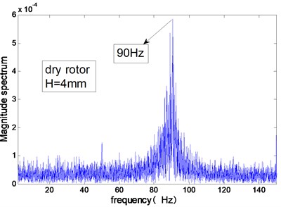
a) Air in annulus
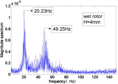
b) Water in annulus
Following the procedure of testing the modal frequency stated above, the modal frequencies of the test rig under different conditions are tested. The influence of the annular flow with different axial length on the modal frequency of the test rig is summarized. When the rotor radius is 61 mm, the average gap thickness between the rotor and stator is 8 mm. Under this condition, the modal frequencies of the test rig for the annular flow with different axial lengths are shown in Table 2.
When the rotor radius is 65 mm, the average gap thickness between the rotor and stator is 4 mm. Under this condition, the modal frequencies of the test rig for the annular flow with different axial length is shown in Table 3.
When the rotor radius is 67 mm, the average gap thickness between the rotor and stator is 2 mm. Under this condition, the variation of the modal frequencies of the test rig for the annular flow with different axial length is shown in Table 4.
Table 2Modal frequencies of the test rig for different axial lengths of the annular flow (H= 8 mm)
Axial length of annular flow (mm) | 0 | 120.5 | 196 | 261 | 365 |
Modal frequency of the rotor (Hz) | 97.2 | 61.23 | 46.02 | 39.55 | 32.04 |
Modal frequency of the stator (Hz) | – | 194.67 | 178.7 | 87.58 | 68.102 |
Table 3Modal frequencies of the test rig for different axial lengths of the annular flow (H= 4 mm)
Axial length of annular flow (mm) | 0 | 126.7 | 198.5 | 271.2 | 365 |
Modal frequency of the rotor (Hz) | 90 | 46.3 | 34.24 | 27.87 | 21.8 |
Modal frequency of the stator (Hz) | – | 195 | 106 | 75 | 51.4 |
Table 4Modal frequencies of the test rig for different axial lengths of the annular flow (H= 2 mm)
Axial length of annular flow (mm) | 0 | 126.5 | 166.5 | 215.9 | 306.6 | 365 |
Modal frequency of the rotor (Hz) | 80.72 | 35.76 | 28.42 | 23.97 | 18.74 | 15.75 |
Modal frequency of the stator(Hz) | – | 144.5 | 111.6 | 84.81 | 59.04 | 41.72 |
In the modal test, when the annular gap is full of air and the rotor is dry, impact the stator by the hammer. The natural frequency of the stator can’t be obtained. As the stator is made of plexiglass, the stator has small mass and relatively high damping coefficients. The motion of the stator under the hammer impact may be over damped. So the modal frequency cannot be tested. However, when there is water in the annular gap, the added mass effect of the annular flow is significant. Then the modal frequency of the stator can be tested.
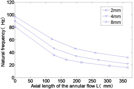
From Fig. 7, the rotor modal frequency decreases rapidly as the increase of the axial length of the annular flow. When the axial length of the annular flow is zero (0 mm), there is no water in the annulus. The dry rotor with bigger gap thickness has higher natural frequency. The connecting flanges for the rotors with different radii are the same. The bending stiffness of the flange doesn’t change. When the gap thickness is big, the rotor radius is small and the mass of the rotor is small. So the modal frequency of the dry rotor with bigger gap thickness is higher. For different axial length of the annular flow, the natural frequency of the rotor with bigger gap thickness is always bigger, too. That indicates that the added mass of the annular flow is smaller for bigger gap thickness.
Fig. 7Experimental results of the rotor modal frequencies for different axial length of the annular flow
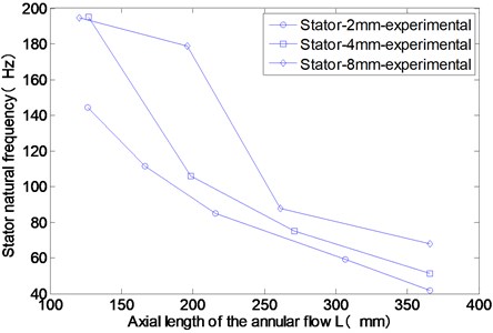
As shown in Fig. 8, under the annular flow, the modal frequencies of the stator decrease rapidly with the increase of the axial length of the annular flow. According to the Newton’s third law, the fluid force acted on the stator has the same magnitude to the fluid force acted on the rotor and has the opposite direction. During the experiment, when the gap thickness of the annulus is 8 mm, the modal frequency of the stator is always the biggest. However, the structure of the stator doesn’t change in the experiment. This phenomenon also indicates that the added mass of the annular flow decrease when the average gap thickness increases.
Fig. 8Experimental results of the stator mode frequencies for different axial lengths of the annular flow
4. Dynamic finite element model of the test rig
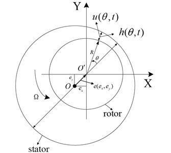
Geometry of the fluid annulus for two dimensional model of the annular flow is shown in Fig. 9. The stator center which is also the base of the fixed coordinate is . The rotor center is . is the rotor eccentricity and is the eccentricity ratio. is the azimuth, is the time. is the gap-averaged tangential flow velocity in the annulus, is the annular gap thickness, is the gap-averaged pressure in the annulus. is the rotor radius. The rotor spinning velocity is and .
Fig. 9Geometry of the fluid annulus
The linearized fluid forces on the immersed rotor can be written in the usual form:
where , is the displacement of the rotor center. , is the velocity of the rotor center. , is the velocity of the rotor center.
The coefficients can be obtained from the reference [12, 13]:
where is the added mass matrix, is the damping matrix, is the stiffness matrix, and , is the water density, gap ratio . is the axial length of the annular flow.
In Eq. (1), is generated from the two-dimensional annular flow model which is derived by assuming that the axial length of the annular flow is infinite. is suitable for the annular flow with relative long axial length.
The rotor and stator of the test rig is modeled by the finite element method. Based on the Timoshenko beam theory, the finite elements of the rotor and stator are derived by using the Galerkin method. The finite elements are suitable for the rotor with big diameter. Every element has two nodes. Each node of the element has four freedoms, two translations and two angular bending.
The outer shell is made of plexiglass. The rotor is made of Aluminum alloy. The parameters of the two materials are shown in Table 5. The mass of the pressure transducer on the outer shell is 0.16 kg and the mass of the temperature transducer is 0.15 kg. These mass of the transducers are added to the specified nodes of the stator.
Table 5Material parameters of the rotor and stator
Material | Young modulus (Pa) | Density (kg/m3) | Poisson’s ratio |
Plexiglass | 3×10⁹ | 1200 | 0.3 |
Aluminum alloy | 72×109 | 2700 | 0.3 |
As shown in Fig. 10, the stator is divided into 22 elements and has 23 nodes. The node at the lower end of the stator is set to be fixed. The freedoms of the finite element model of the stator are 88. The rotor is divided into 25 elements and has 26 nodes. The upper end of the rotor is connected with the spindle of the CNC machine tool by the flange. The node at the upper end of the rotor only has two bending freedoms. The translation freedoms are restricted due to the flange. The total freedoms of the finite element model of the rotor is 102. In the dynamic finite element model of the rotor, the flange is represented by two bending springs with specified stiffness. According to the natural frequency test of the dry rotor, the equivalent bending stiffness of the flange between the rotor and the spindle is 1.55×10⁵ (N∙m)/rad. By utilizing the bending stiffness, the first modal frequency of the dry rotor calculated by the dynamic model is the same to the experimental results.
Appendix presents the beam element matrices, the assembly of the full matrices and the coupling procedure of the rotor and stator by the annular flow. This dynamic model is used to study the dynamic force effect of the annular flow with finite axial length.
Fig. 10Dynamic model of the test rig
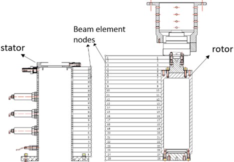
a) Element division of the test rig
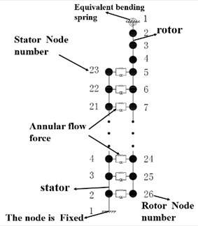
b) Schematic diagram of the dynamic model
The dynamic equations of the test rig are written as Eq. (2):
where is the vector of the displacements and rotation angles of the nodes. is the system mass matrix, is the system damping matrix, is the system stiffness matrix. is the rotor unbalance force. The rotor and stator of the test rig are coupled by the annular flow.
When the axial length of the annular flow is short in the experimental test, the 3D effect of the annular flow is important. A new modification coefficient is introduced in the theoretical model to represent the 3D effect of the annular flow with finite axial length. When the rotor vibrates inside the stator, the leakage of the fluid at the two end of the annulus with short axial length, has important influence on the pressure field of the annular flow. In this condition, the force generated by the annular flow with short axial length is overestimated by using the two-dimensional annular flow model.
From Eq. (1) and (2), the coupled formulation of the test rig is obtained:
where , , .
By introducing the state-space vector, the second-order differential equations of the test rig can be rewritten by a state-space first-order differential equation as given by:
where:
The system modal behavior, as a function of and , is given by the complex eigenvalues and complex eigenvectors of matrix in Eq. (4). For each eigenvalue , the corresponding modal frequency and damping ratio are calculated as:
5. The modification coefficient for annular flow with short axial length
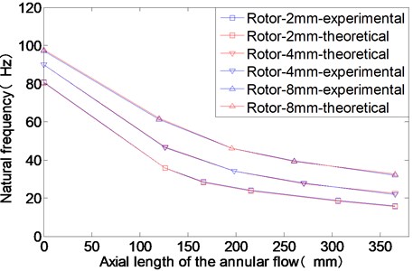
According to the experimental results, the coefficient is chosen to make that the theoretical results of the rotor’s modal frequencies are the same to the experimental results at different axial length of the annular flow. The theoretical and experimental results of the rotor natural frequencies for different axial length of the annular flow are illustrated in Fig. 11.
Fig. 11The experimental and theoretical results of the rotor modal frequencies for different axial lengths of the annular flow
When the gap thickness is 2 mm, 4 mm and 8 mm, the corresponding modification coefficients are calculated based on the experimental results and are shown in Tables 6, 7, 8.
Table 6Theoretical results of the modal frequencies of the test rig for different axial length of the annular flow (H= 2 mm)
Axial length of the annular flow (mm) | 0 | 126.5 | 166.5 | 215.9 | 306.6 | 365 |
Rotor natural frequency (Hz) | 80.49 | 35.67 | 28.24 | 23.83 | 18.43 | 15.55 |
Stator natural frequency (Hz) | 184.3 | 192.9 | 157.1 | 104.7 | 48.93 | 29.97 |
Modification coefficient | – | 0.27 | 0.4 | 0.47 | 0.75 | 0.9 |
In Fig. 12, the theoretical results of the stator’s modal frequencies under different conditions are compared with the experimental results. The two results are in agreement with each other which means that the dynamic model of the test rig is accurate. The modification coefficient which represent the 3D effect of the annular flow with short axial length is reasonable. The force generated by the annular flow decreases quickly with the decrease of the axial length.
Table 7Theoretical results of the modal frequencies of the test rig for different axial length of the annular flow (H= 4 mm)
Axial length of the annular flow (mm) | 0 | 126.74 | 198.46 | 271.18 | 365 |
Rotor natural frequency (Hz) | 90 | 46.7 | 34.02 | 27.6 | 22.63 |
Stator natural frequency (Hz) | 184.3 | 178.7 | 128.9 | 77.7 | 43.31 |
Modification coefficient | – | 0.31 | 0.5 | 0.71 | 1 |
Table 8Theoretical results of the modal frequencies of the test rig for different axial length of the annular flow (H= 8 mm)
Axial length of the annular flow (mm) | 0 | 120.49 | 195.88 | 261.06 | 365 |
Rotor natural frequency (Hz) | 97.84 | 61.9 | 46.03 | 39.37 | 32.58 |
Stator natural frequency (Hz) | 184.3 | 181.4 | 149.34 | 112.23 | 61.54 |
Modification coefficient | – | 0.35 | 0.59 | 0.79 | 1.1 |
Fig. 12The experimental and theoretical results of the stator modal frequencies for different axial length of the annular flow
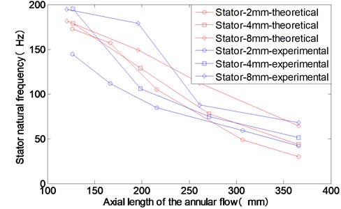
Fig. 13The modification coefficients of the annular flow for different axial length
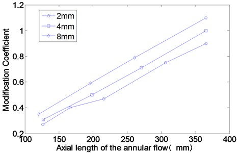
As shown in Fig. 13, the modification coefficient is almost linear with the axial length of the annular flow. It is indicated that the force generated by the annular flow with short axial length may have a positive correlation with the square of the axial length of the annulus. The shorter of the annular flow’s axial length, the stronger of the 3D effect of the annular flow. The leakage of the fluid at the two end of the annulus has great influence on the added mass effect of the annular flow with short axial length. However, the two-dimensional annular flow model is accurate for predicting the force effect of the annular flow when the axial length is long enough. When the gap thickness is bigger, the modification coefficient is bigger, too.
6. Conclusion
In this article, a test rig to study the force effect of the annular flow between the rotor and stator is built in a CNC machine tool. The dynamic finite element model of the test rig is established. Based on the two-dimensional annular flow model, the added mass, damping and stiffness matrices are evaluated to represent the coupling force generated by the annular water flow between the rotor and stator. However, the 3D effect of annular flow with short axial length is significant. In order to study the 3D effect of the annular flow, a modification coefficient is proposed in the finite element model of the test rig. Hammer impact method is used to test the modal frequencies of the test rig under different conditions. According to the experimental results, the modification coefficient is obtained by making that the theoretical results of the rotor frequencies are the same to the experimental results at different axial length of the annular flow. The experimental results and the theoretical results show that the added mass effect of the annular flow with big gap average thickness is significant and can reduce the modal frequency of the rotor by a large margin. The transient force acted on the rotor by the annular flow predicted by the two-dimensional annular flow model is accurate for the annular flow with long axial length. With the increase of the axial length of the annular flow, the modal frequencies of the rotor and stator decrease quickly. For the annular flow with short axial length, the 3D effect has very important influence on the force generated by the annular flow. The modification coefficient is almost linear with the axial length of the annular flow. As the annular flow force is also linear with the axial length, the annular flow force for short axial length may have a positive correlation with the square of the axial length of the annulus.
References
-
Paıdoussis M. P. Fluid-Structure Interactions, Slender Structures and Axial Flow. Vol. 2. Elsevier Academic Press, London, 2003.
-
Chen S. S. Flow-Induced Vibration of Circular Cylindrical Structures. Hemisphere Publishing, Washington, 1987.
-
Brennen C., Acosta A. Fluid-induced rotordynamic forces and instabilities. Structural Control and Health Monitoring, Vol. 13, 2006, p. 10-26.
-
Kaneko S., Nakamura T., Inada F., Kato M. Flow Induced Vibrations: Classifications and Lessons from Practical Experiences. Elsevier, Amsterdam, The Netherlands, 2008.
-
Jansson I., Åkerstedt H. O., Aidanpää J., Staffan Lundström T. The effect of inertia and angular momentum of a fluid annulus on lateral transversal rotor vibrations. Journal of Fluids and Structures, Vol. 28, Issue 1, 2012, p. 328-342.
-
Hamrock B. J. Fundamentals of Fluid Film Lubrication. McGraw Hill, New York, 1994.
-
Flouros M., Hendrick P., Outirba B., Cottier F., Proestler S. Thermal and flow phenomena associated with the behavior of brush seals in aero engine bearing chambers. Journal of Engineering for Gas Turbines and Power, Vol. 137, Issue 9, 2015.
-
Du K., Li Y., Suo S., Wang Y. Dynamic leakage analysis of noncontacting finger seals based on dynamic model. Journal of Engineering for Gas Turbines and Power, Vol. 137, Issue 9, 2015.
-
Tschoepe D. P., Childs D. W. Measurements versus predictions for the static and dynamic characteristics of a four-pad, rocker-pivot, tilting-pad journal bearing. Journal of Engineering for Gas Turbines and Power, Vol. 136, Issue 5, 2014.
-
Fritz R. J. The effects of an annular fluid on the vibrations of a long rotor, part 1 – theory. Journal of Basic Engineering, Vol. 2, 1971, p. 923-929.
-
Fritz R. J. The effects of an annular fluid on the vibrations of a long rotor, part 2 – test. Journal of Basic Engineering, Vol. 4, 1970, p. 930-937.
-
Antunes J., Axisa F., Grunenwald T. Dynamics of rotors immersed in eccentric annular flow. Part 1: theory. Journal of Fluids and Structures, 10, 1996, p. 893–918.
-
Grunenwald T., Axisa F., Bennett G., Antunes J. Dynamics of rotors immersed in eccentric annular flow. Part 2: experiments. Journal of Fluids and Structures, 10, 8, 1996, p. 919–944.
-
Antunes J., Mendes J., Moreira M., Grunenwald T. A theoretical model for nonlinear planar motions of rotors under fluid confinement. Journal of Fluids and Structures, Vol. 13, Issue 1, 1999, p. 103-126.
-
Moreira M., Antunes J., Pina H. A theoretical model for nonlinear orbital motions of rotors under fluid confinement. Journal of Fluids and Structures, Vol. 14, Issue 5, 2000, p. 635-668.
-
Moreira M., Pina H., Antunes J. Nonlinear vibrations of vertical asymmetrically-supported rotors under fluid confinement: theoretical results. 1st International Conference on Fluid Structure Interaction, Fluid Structure Interaction, Vol. 30, 2001, p. 97-106.
-
Moreira M., Antunes J., Pina H. A Symbolic-numerical method for nonlinear rotor dynamics under fluid confinement. International Journal of Nonlinear Sciences and Numerical Simulation, Vol. 3, Issue 1, 2002, p. 35-44.
-
Moreira M., Tissot A., Antunes J. Experimental validation of theoretical models for the linear and nonlinear vibrations of immersed rotors. International Journal of Rotating Machinery, Vol. 8, Issue 2, 2002, p. 87-98.
-
Moreira M., Antunes J., Pina H. Nonlinear analysis of the orbital motions of immersed rotors using a spectral/Galerkin approach. Communications in Nonlinear Science and Numerical Simulation, Vol. 7, Issue 3, 2002, p. 123-137.
-
Moreira M., Antunes J., Pina H. An improved linear model for rotors subject to dissipative annular flows. Journal of Fluids and Structures, Vol. 17, Issue 6, 2003, p. 813-832.
-
Sun Qiguo, Fang Hairong Yu Lie The dynamic modelling of 3D large gap annular flow. Lubrication Engineering, Vol. 165, Issue 5, 2004, p. 7-9.
-
Sun Qiguo Dynamic characteristics of an eccentric finite-length large gap annular flow. Journal of Vibration and Shock, Vol. 30, Issue 10, 2004, p. 227-230.
About this article
