Abstract
Accuracy of machine tool with a gantry frame is reduced due to the vibration caused by inertial force impact. Hydrostatic slider bearings are considered as key structures of machine tools, which play an important role in improving impact and vibration resistance ability as dynamic performance. In this work, an incline model which combines bending deformation with linear displacement is simulated using working conditions of the straddle carrier under inertial force impact as an imitation of vibration amplitude. Using finite difference method (FDM), numerical solution of pressure distribution in oil pad can be determined by solving the Reynolds equation. Relationship between carrying capability and incline extent can be determined by analyzing the resolution of the Reynolds equation. A new type of oil pad size optimizing process is propose in this work, which is carried out based on the analysis of the analyzing result to enhance the inertial force resistance ability. Finally, impact resistance capacity of machine tool can be improved by sacrificing oil film thickness.
1. Introduction
Hydrostatic slider bearings are widely used for a range of applications including in a number of industrial instruments and are considered to be among the typical uses of hydrostatic supporting systems. Lubricating oil is pumped into oil pads, which are fixed on the slide carriage. This results in the formation of an oil film between the edges of the oil seal of the oil pads and the slider rail. A major part of the loading ability for these supporting surfaces is provided by pressurized oil within a pocket on the oil pad and the oil film at edge of the oil seal, which maintains the pressure in pocket. This is referred to as the hydrostatic effect. Hydrostatic slider bearings have a large carrying capacity. As a result of this, hydrostatic bearing are mainly used in huge machines such as heavy machine tools with mobile gantry frames or straddle carriers, where the weight of the carrier can exceed hundred tons. Starting or stopping the gantry frame would result in vibrations due to the accelerating inertial force. This results in reduced machining accuracy and in some cases could also damage the work piece. Therefore, impact resistance should be taken into consideration along with the static carrying capability when designing or analyzing hydrostatic slider bearings. The resistant ability is evaluated by the inclination extent which is regarded as the amplitude of inertial variation. Smaller inclination under greater inertial force means better resistant ability. Typically, studies on hydrostatic supporting systems are based on the resolution of the Reynolds equation.
Several groups have carried out research on hydrostatic slider bearings based on the Reynolds equation, and the results reported were verified by applying them to solve the practical engineering problems [1, 2]. Reynolds equation is a second order partial differential equation, which includes parameters as pressure, film thickness, oil viscosity and density and loading surface velocity. Before being solved, the Reynolds equation has to be modified according to the working condition [3, 4]. Pressure distribution in the oil pad determines carrying capacity, which is influenced by film thickness [5]. Uneven distribution of the oil film due to inclination caused by inertial force impact should be taken, which would influence the carrying capacity is taken into consideration in the current work. A modified Reynolds equation which takes into account the influence of film thickness variation is needed [6, 7]. Lubricating oil in hydrostatic systems is always considered as incompressible due to the fact that the influence of fluid density can be neglected. In addition, moving velocity of the gantry frame is relatively low, which allows temperature variation and non-Newtonian features to be neglected. As a result, effect of oil viscosity can also be ignored [8, 9]. The partial derivative in respect of time in the Reynolds equation is ignored in many researches because hydrostatic systems always have relatively high damping coefficient [10]. So this work mainly focuses on the transient impact like inertial force impact. The Reynolds equation is always solved numerically. This is because the analytical solution of is difficult to solve, even in cases where the equation has been modified. Finite difference method (FDM) is a widely used numerical approach for solving partial differential equations such as the modified Reynolds equation [11]. Using FDM, the Reynolds equation can be approximated into finite algebraic equations, which can be solved using the Gauss-Seidel method. This can then be used to determine numerical pressure at each node [12]. Using successive over-relaxation (SOR) method allows to make the computations more stringent and also allows for improved iteration speed [13]. Numerical results demonstrate reliability of the method within a fixed error tolerance [14]. Oil flow rates are also influenced by inclination caused by inertial forces. The flow rate along with pressure distribution determines carrying capacity of hydrostatic slider bearing [15, 16]. According to the multi-body system (MBS) theory, tool tip position is significantly affected by small geometrical errors. These errors are typically caused by inclination of slider and are amplified through the structure of the frame. All these errors reduce machining precision [17, 18]. Therefore, inclination error of slide carriage studied in this work is limited to relatively small scales. An optimizing process is used to determine parameters which can be used to improve inertial force resistance based on the relationship between slider inclination and carrying ability. An optimal solution is determined based on testing carried out in several experiments [19, 20].
Here, the Reynolds equation is modified to solve pressure distribution in a sloped oil pad according to the working condition of hydrostatic slider bearings. Bending deformation and linear displacements are both taken into consideration to simulate shape of the oil film. The Reynolds equation is then converted into algebraic form using FDM and is solved numerically using the Gauss–Seidel iterative method and accelerated using SOR. Relationship between slider inclination and carrying capacity is obtained using the pressure distribution and oil supply mode. Here, oil supply mode was set with constant flow rate pump, which is widely used in heavy devices. Optimal oil pad design to enhance impact resistance ability can be determined based on current analysis. The resistance capability is estimated by the inclination extent under equivalent inertial impact or, in another word, the resistant moment generated by equivalent inclination.
2. Methodology
2.1. Model for hydrostatic slider bearing under inertial force impact
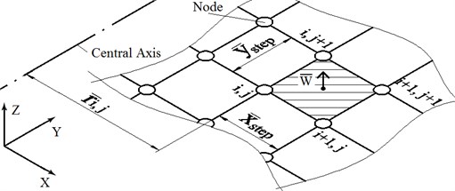
Hydrostatic slider bearings are mainly used in large machine tools to support and lubricate the mobile gantry frame. In this work, two slider rails were fixed on the ground and two slide carriages were allowed to move on the rails. Several oil pads were fixed along two symmetrical rows on the bottom side of each slide carriage. The model for slider bearing and oil pad is shown in Fig. 1.
Fig. 1Model of hydrostatic slider bearing
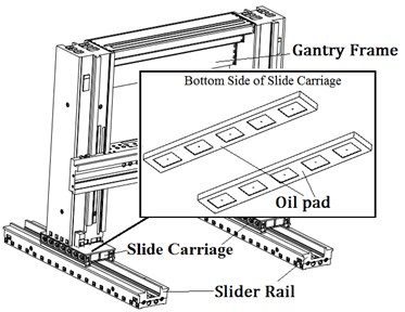
a) Oil pads on machine tool
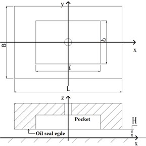
b) Model of oil pad
In Fig. 1, is the length of the oil pad, is the width of the oil pad, is the length of the oil pocket, is the width of oil the pocket and is the film thickness.
Impact inclination of the slider bearing is caused by inertial force, which means that the incline extent is associated with the mass of gantry frame and moving acceleration.
Assuming that, is inertial force, is mass of the gantry frame, is acceleration, is the offset from center for the gantry frame, is inertial moment, is number of oil pads coded 1, 2,…, :
Every oil pad is fixed at the bottom of slide carriage, so deformation or displacement of slide carriage will directly affect film thickness between oil pad and slider rail. Under the impact of inertial force, slope caused by inclination and bending caused by inertial moment will both influence film thickness. Bending deformation is typically associated with working conditions as inertial force; Young modulus of the material, geometry of the carriage, etc. Extent of this type of bending deformation is related to square of the length of the part loaded with constant moment. No deformation occurs on the part without loaded, which results in the bending deformation relationship to be linear. To analyze the slider bearing under inertial impact, the slide carriage can be divided in two parts undergoing bending deformation and linear displacement. At the boundary point between these two parts, value of the function and derivative are considered to be continuous. Model of displacement is shown in Fig. 3.
Fig. 2Inertial force impact on slider bearing
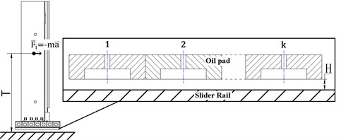
Fig. 3Displacement assumption of oil pads
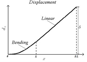
Displacement extent is written as:
where, is deformation along the coordinate, is the boundary point between two parts, is maximum offset of . Different values stand for a unique inclination situation. Impact of inertial force on slider bearing is reflected on the displacement of slide carriage, so the offset is able to represent impact instead of or . Film thickness can be represented as the summation of original film thickness and displacement :
For analysis, the following dimensionless variables are used:
where, is pressure, is pressure in the oil pocket, is carrying capability, is volumetric flow rate, is carriage velocity, is film thickness and is viscosity. In addition, is dimensionless pressure, is dimensionless size on coordinate, is dimensionless size on coordinate, is dimensionless size on coordinate, is dimensionless carrying capability, is dimensionless moment on coordinate, is dimensionless flow rate, is dimensionless carriage velocity and is dimensionless film thickness.
Moving speed of hydrostatic slider bearing has always been found to be low in most applications. Viscosity and density variations can be ignored, as there is no significant temperature change. The modified Reynolds equation for analyzing the hydrostatic slider bearing is written as [7]:
2.2. Finite difference method
Partial differential equations (PDE) such as Eq. (5) are difficult when solved analytical, however using FDM, the PDEs can be converted into algebraic equations, which are relatively easier to solve. According to Taylor's theorem, function like pressure distribution can be written as:
where, is the step length for the coordinate and it can be written as, and is numerical counts of the elements on and coordinate respectively. The precision of the numerical solution is able to be improved by choosing appropriate . So all polynomials beyond quadratic could be ignored as infinitesimals and PDE can be approximately written as [12]:
Eq. (5) is converted and reorganized as:
where, is step length for the coordinate. Discrete nodes of FDM are shown in Fig. 4.
Where, central axis is the neutral axis, where all the moments are zero. In this work, the central axis is located in the middle of the slide carriage along the coordinate. is the distance from the central axis to the node.
Fig. 4Discrete nodes of FDM
Eq. (8) is the iterative form of the modified Reynolds equation, which can be solved numerically. Pressure distribution can be determined by using Gauss-Seidel method and SOR acceleration, whose convergence has been verified in many researches [10]. Boundary condition is written as:
at each node is prerequisite to solve for the pressure distribution. However, dimensionless film thickness is highly associated with the oil supply mode, loading situation and pressure distribution. To resolve this contradiction, film thickness can be chosen artificially as a trail value and then pressure distribution can be solved. The dimensionless carrying capability and flow rate of the th oil pad, namely and are determined based on the pressure distribution. The total carrying capability for a single row of oil pads is regarded as the summation of all the oil pads. Real load of the hydrostatic slider bearing is approximately equal to the weight of the gantry frame. Supply flow rate is constant, so film thickness can be determined based on , and .
According to Eq. (4):
where, is the supply flow rate for each oil pad.
Pressure distribution can be affected by inclination of the slide carriage, so needs to be solved based on . and need to be renewed based on the result of . Then, an updated film thickness is determined, which means the iteration moves to the next round:
where, is the acceleration due to gravity.
Successive iterations are carried out until numerical results match the preset error tolerance to determine depend on which and can be solved as while. is the ability of hydrostatic slider bearing to resist the inertial force impact:
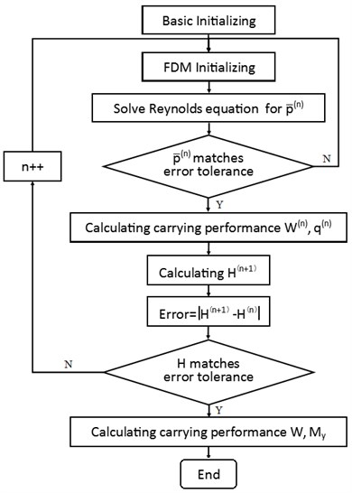
The flow chart illustrating the iteration algorithm is shown in Fig. 5 [16].
Fig. 5Flow chart illustrating the iteration algorithm
3. Results and discussions
3.1. Incline impact on carrying capability of single oil pad
According to the displacement assumption shown in Fig. 3 and Eq. (2), oil pads generate moment to resist incline impact. Values and ranges of parameters used in the analysis are listed in Table 1.
Before carrying out the carrying capability analysis, the displacement assumption should be verified. In this work, is limited to the range between 0 and 2×10⁻⁵ m. This range for poses a measurement difficulty. However, finite element modeling (FEM) software has been proved to be reliable for small deformations in this range. A comparison of displacement assumption shown in Fig. 3 with FEM result determined using simulations carried out in ANSYS 14.5 are shown in Fig. 6.
Fig. 6Verification of displacement assumption
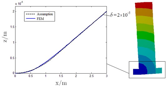
Table 1Value/range of major parameters
Parameter | Value/range |
3×10⁵ kg | |
3.5 m | |
0.6 m | |
0.4 m | |
0.36 m | |
0.24 m | |
5 | |
0.06 Pa·s | |
0-2×10⁻⁵ m | |
5×10⁻⁵ m | |
3.3×10⁻⁶ m3/s | |
Error tolerance [16] | 1×10⁻⁷ |
In Fig. 6, is set as 1.3 m and is set as 2×10⁻⁵ m to match the FEM result. Maximum error between the displacement assumption and FEM result is about 7 %, which implies that results based on the assumption are reliable to set permissible level.
In an ideal model without inclination, namely 0 m, pressure distribution determined by FDM is shown in Fig. 7.
Fig. 7Dimensionless pressure distribution for a single oil pad
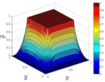
a) Distribution in 3-D
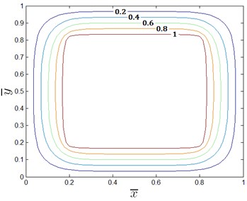
b) Distribution in contour
In Fig. 7, dimensionless pressure is 1 in the oil pocket and 0 at the outer boundary of oil seal edge. Based on the results, dimensionless carrying performance can be determined with 0.6209 and 0.9798. According to Eq. (10), relationship between carrying capability and film thickness is shown in Fig. 8.
According to the constant flow rate oil supply mode, carrying ability decreases with increasing film thickness and increases with increasing supply flow rate. In most working conditions, load on the hydrostatic bearing is predominantly the weight of the gantry frame, which implies that the loading is stable. Therefore, carrying capacity and film thickness remain constant in an ideal model without inclination. Under the influence of inertial force impact, dimensionless carrying capability and flow rate will be change with the slope. Variation of dimensionless carrying ability and flow rate for a single oil pad with linear inclination is shown in Fig. 9.
In Fig. 9, dimensionless carrying capacity and flow rate are both increasing with rising but the extent at which flow rate increases is more than the carrying capability. With rising from 0 to 1×10⁻⁵, increases about 0.16 %, which can be considered as negligible growth; increases 5.9 %, which is approximately 36 times . When loading, with geometry of oil pad and supply flow rate held as constants, film thickness can be written as:
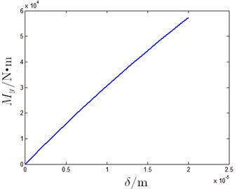
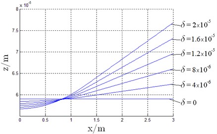
From Eq. (13), it can be concluded that for this type of linear inclination of single oil pad can reduce the film thickness . However, uneven pressure distribution in each oil pad generates the moment to resist inclination and this serves as the working principle for the oil pads. Relationship between , and when 3.3×10⁻⁶ m3/s is shown in Fig. 10.
Fig. 8Change in carrying ability for different oil film thickness
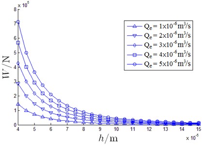
Fig. 9Slope impact on dimensionless carrying ability and flow rate
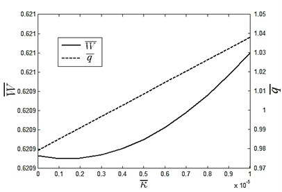
Fig. 10Slope impact on oil film thickness and moment
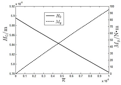
With increasing slope rate and decreasing film thickness, increases collision possibility for oil pad and slider rail. This could result in catastrophic damage to the equipment. On the contrary, resisting moment can only be produced due to oil pad inclination. Based on this, it can be inferred that an optimization process to improve the inertial impact resistant ability and prevent the oil film form breaking down simultaneously in critical.
3.2. Inertial force impact on carrying performance of slider bearing
When, is set as 5, there are 10 oil pads fixed on each slide carriage and 20 on the slider bearing. Due to symmetry, only 5 oil pads on the side of slide carriage are needed for analysis, which are able to provide a quarter of the carrying capacity for the whole hydrostatic slider bearing. Displacement of 5 oil pads can be determined based on the assumptions shown in Fig. 3 and carrying capability can be solved according based on the algorithm shown in Fig. 5. Results are shown in Fig. 11.
Fig. 11Inertial force impact on 5 oil pads
a) Moment
b) Film thickness
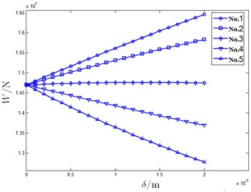
In Fig. 11, the slide carriage appears to be horizontal and there is no moment in the ideal model when 0 m. With increase in , moment generated by oil pads increases with the oil film sinking caused by the reduced carrying ability, which corresponds results shown in Fig. 10. When 2×10⁻⁵ m, film thickness decreases approximately by 3.9 %. In addition, film thickness of the No. 5 oil pad shown in Fig. 11 decreases while that of the No. 1 oil pad increases with rising . This implies that the supporting ability of No. 1 oil pad is larger than the No. 5. Therefore, details for every oil pad is needed as each oil pad has different contribution to resist the inertial force impact. Results are shown in Fig. 12.
Fig. 12Inertial force impact on oil pads carrying performance
a) Carrying ability
b) Moment
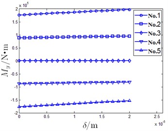
From Fig. 12, it can be seen that the carrying capabilities are same when 0 m. No. 1 and No. 2 oil pads are fixed on one side of central axis and moments are in the positive direction. Whereas, the No. 4 and No. 5 oil pads are fixed on the other side of central axis and their moments are along the negative direction. Moment generated by No. 3 oil pad is small because it is fixed near central axis. With increase in , carrying capacity of the No. 1and No. 2 oil pad increases while that of the No. 4 and No. 5 oil pad decreases. Carrying ability of No. 3 oil pad increases slightly. Moment produced by 5 oil pads increase simultaneously whose algebraic summation is the inertial force resistant moment.
3.3. Inertial force resistance ability optimizing of hydrostatic slider bearing
Form Fig. 12, it can be observed that moment variations for the No. 1 and No. 5 are larger compared to the No. 3 oil pad. This is because of the different contribution by each oil pad. Due to this fact, optimizing process can focus on changing the proportion of each oil pad. One practical method is to change the length of the oil pad. Stable carrying performance cannot be achieved if only is altered without changing oil pocket proportion variation. This optimizing is able allows improving the inertial force resistance capability without influencing the static supporting capacity. Considering acceleration and deceleration inertial forces to be symmetrical, No. 1 and No. 5 oil pad lengths should be equal, and No. 2 and No. 4 should be equal. Also, total length of 5 oil pads must remain constant and every oil pad must greater than 0 m. Constraint conditions for the optimizing process can be written as:
According to the constraint conditions shown in Eq. (14), every oil pad length is determined by established and . Since, carrying capability cannot be affected by any changes in and optimizing schemes are evaluated by film thickness and resistant moment. When, 2×10⁻⁵ m using different and , supporting performance of hydrostatic slider bearing is shown in Fig. 13.
According to the results shown in Fig. 13, maximum film thickness is seen when 0.6, 0.6, 0.6 and minimum value of film thickness is seen when 0.1, 1.35, 0.1. Maximum moment occurs when 0.9, 0.15, 0.9 and minimum is seen when 0.1, 0.95, 0.9. Taking the supporting performance when 0.6, 0.6, 0.6 as criterion and , contrasting optimizing results for several cases are listed in Table 2.
Table 2Optimizing results of several cases
Case | |||||
1 | 0.6 | 0.6 | 0.6 | 1.00 | 1.00 |
2 | 0.4 | 0.7 | 0.8 | 0.976 | 0.732 |
3 | 0.5 | 0.6 | 0.8 | 0.993 | 0.847 |
4 | 0.8 | 0.5 | 0.4 | 0.983 | 1.34 |
5 | 1.0 | 0.4 | 0.2 | 0.923 | 1.99 |
6 | 0.1 | 1.35 | 0.1 | 0.804 | 1.23 |
7 | 0.1 | 0.95 | 0.9 | 0.905 | 0.591 |
8 | 0.9 | 0.55 | 0.1 | 0.975 | 1.82 |
9 | 0.9 | 0.15 | 0.9 | 0.919 | 2.02 |
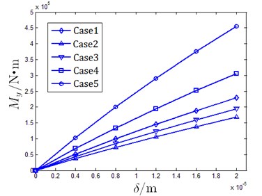
Impact of on moment for case 1 to case 5 is shown in Fig. 14.
Form Table 2 and Fig. 14, it can be concluded that changes in regulation of moment under altering are similar for different cases though the values are distinct. Case 1 is the criterion where film thickness is maximum, which means that it is the safest condition preventing oil film from breaking down. Case 6 improves the moment by about 23 % but there is a 20 % loss in film thickness. Case 7 is the worst optimizing case that sees a 10 % loss in film thickness but also reduces the moment by nearly 40 %. Case 9 is the optimal plan; in this range about 100 % improvement moment is observed with only 10 % loss in film thickness. However, oil pad lengths in Case 6-Case 9 are extreme condition, which are not practical in real working situations with constraints such as limited width of oil seal edge, film thickness demand, limitations in oil pad manufacture. More conditions are required to determine the final optimizing scheme. This method proved to be effective to improve inertial force resistance ability by sacrificing a small oil film thickness or by reducing the incline extent under comparable inertial force impact.
Fig. 13Carrying performance for different oil pad lengths
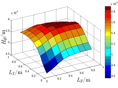
a) Film thickness in 3-D
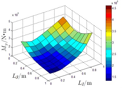
b) Moment in 3-D
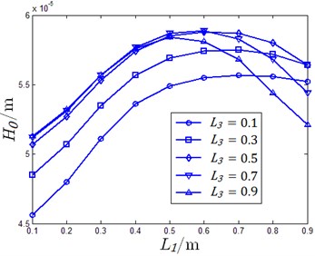
c) Film thickness for different
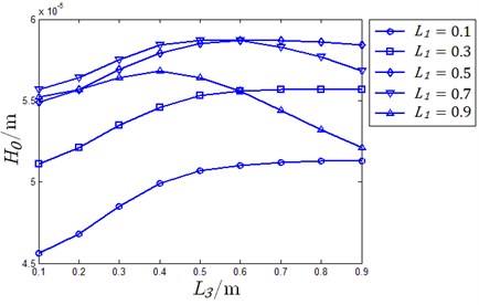
d) Film thickness for different
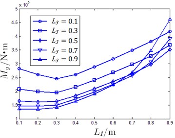
e) Moment for different
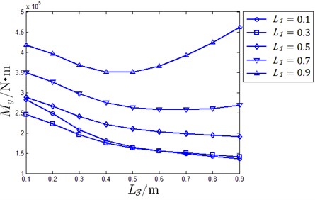
f) Moment for different
Fig. 14Moment in different offset of Case 1-Case 5
4. Conclusions
In the present work, Reynolds equation is solved using FDM and Gauss-Seidel method in order to analyze inertial force impact on hydrostatic slider bearing. Bending deformation of slide carriage is taken into consideration to simulate the working condition. Following conclusions can be drawn from the analysis based on the model proposed in this paper.
1. Inclination on slide carriage of hydrostatic slider bearing can be caused by inertial force or vibration impact, which generates the moment to resist leaning. The value of moment is associated with incline extent, geometry of oil pads and oil supply mode.
2. Each oil pad plays a different role in the inertial force restricting ability of the hydrostatic slider bearing. Contribution of every oil pad corresponds to the distance from central axis, which is the foundation of optimizing process.
3. Changing the length of oil pads is a practical method to improve the inertial force resistance ability by reducing film thickness. For instance, moment was improved by 100 % using the optimizing scheme with only 10 % loss in film thickness. However, when film thickness was reduced, a reduction in moment was observed and maximum film thickness can only be obtained when every oil pad has equal length.
References
-
Qiu M. F., Brian N. B., Rob S., Bart R. The accuracy of the compressible Reynolds equation for predicting the local pressure in gas-lubricated textured parallel slider bearings. Tribology International, Vol. 72, 2014, p. 83-89.
-
Ochoa E. de la Guerra, Otero J. Echávarri, López A. Sánchez, Tanarro E. Chacón Film thickness predictions for line contact using a new Reynolds-Carreau equation. Tribology International, Vol. 82, 2015, p. 133-141.
-
Habchi W., Bair S., Qureshi F., Covitch M. A film thickness correction formula for double-Newtonianb shear-thinning in rolling EHL circular contacts. Tribology Letters, Vol. 50, Issue 1, 2013, p. 59-66.
-
Bair S. A Reynolds-Ellis equation for line contact with shear-thinning. Tribology International, Vol. 39, Issue 4, 2006, p. 310-316.
-
Masjedi M., Khonsari M. M. On the effect of surface roughness in point-contact EHL: Formulas for film thickness and asperity load. Tribology International, Vol. 82, 2015, p. 228-244.
-
Wang N. Z., Cha K. C., Huang H. C. Fast convergence of iterative computation for incompressible-fluid Reynolds equation. Journal of Tribology, Vol. 134, Issue 2, 2012, p. 024504.
-
Hsu T. C., Chen J. H., Chiang H. L., Chou T. L. Lubrication performance of short journal bearings considering the effects of surface roughness and magnetic field. Tribology International, Vol. 61, 2013, p. 169-175.
-
Serdar A., Mahmut F. A. A fully coupled 3D thermo-elasto hydrodynamics model for a bump-type compliant foil journal bearing. Tribology International, Vol. 82, 2015, p. 110-122.
-
El Khlifi M. Numerical modeling of non-Newtonian fluids in slider bearings and channel thermohydrodynamic flow. Journal of Tribology, Vol. 129, Issue 3, 2007, p. 695-699.
-
Bompos D. A., Nikolakopoulos P. G. Journal bearing stiffness and damping coefficients using nanomagnetorheological fluids and stability analysis. Journal of Tribology, Vol. 136, Issue 4, 2014.
-
Li Y. Z., Zhou K., Zhang Z. A flow-difference feedback iteration method and its application to high-speed aerostatic journal bearings. Tribology International, Vol. 84, 2015, p. 132-141.
-
Nicoletti R. Comparison between a meshless method and the finite difference method for solving the Reynolds equation in finite bearings. Journal of Tribology, Vol. 135, Issue 10, 2013, p. 044501.
-
Getachew A. D., Prawal S. THD analysis for finite slider bearing with roughness: special reference to load generation in parallel sliders. Acta Mechanica, Vol. 222, Issues 1-2, 2011, p. 1-15.
-
Li J., Chen H. S. Evaluation on applicability of Reynolds equation for squared transverse roughness compared to CFD. Journal of Tribology, Vol. 129, Issue 10, 2007, p. 963-967.
-
Meng X. K., Bai S. X., Peng X. D. Lubrication film flow control by oriented dimples for liquid lubricated mechanical seals. Tribology International, Vol. 77, 2014, p. 132-141.
-
Makoto G., Kei S., Masaaki M., Shigeka Y. Static characteristics of a water-lubricated hydrostatic thrust bearing using a membrane restrictor. Tribology International, Vol. 75, 2014, p. 111-116.
-
Cheng Q., Zhao H. W., Zhang G. J., Gu P. H., Cai L. G. An analytical approach for crucial geometric errors identification of multi-axis machine tool based on global sensitivity analysis. The International Journal of Advanced Manufacturing Technology, Vol. 75, Issue 10, 2014, p. 107-121.
-
Cheng Q., Feng Q. N., Liu Z. F., Gu P. H., Cai L. G. Fluctuation prediction of machining accuracy for multi-axis machine tool based on stochastic process theory. Proceedings of the Institution of Mechanical Engineers, Part C: Journal of Mechanical Engineering Science, 2004.
-
Ji J. H., Fu Y. H., Bi Q. S. Influence of geometric shapes on the hydrodynamic lubrication of a partially textured slider with micro-grooves. Journal of Tribology, Vol. 136, 2014, p. 041702.
-
Fesanghary M., Khonsari M. M. On the optimum groove shapes for load-carrying capacity enhancement in parallel flat surface bearings: theory and experiment. Tribology International, Vol. 67, 2013, p. 254-262.
About this article
The authors would like to thank the National Science and Technology Major Project coded 2013ZX04013-011 and Jing-Hua Talents Project of Beijing University of Technology for supporting the research.
