Abstract
The rotors are often mounted in hydrodynamic bearings. To achieve their optimum performance in a wide range of operating speeds, their stiffness and damping parameters must be adaptable to the current angular velocity. This is offered by application of smart fluids sensitive to a magnetic field. The detailed analysis shows that application of ferromagnetic fluids is possible only for small sliding bearings. For bearings, the operation of which requires to generate high pressure, this concept fails. This arrived at the idea to use the ferrofluids-based magnetorheological fluids as a lubricant. This paper deals with the development of a basic concept of such a bearing and with the principle considerations on the magnetic flux generation and its propagation in the bearing housing and the lubricating layer. The developed mathematical model of the bearing was applied for investigation of the influence of changes of the lubricant properties by means of a magnetic field on the vibration attenuation of a rigid rotor excited by unbalance. The pressure distribution in the bearing gap is governed by the Reynolds equation adapted to non-Newtonian lubricant, the yielding shear stress of which depends of magnetic induction. The magnetic flux propagation in the bearing housing is described by the Hopkinson law. The results of the simulations show that the increase of the yielding shear stress of the lubricant by action of a magnetic field rises the bearing load capacity and does not destabilize the rotor vibration.
1. Introduction
The rotors are often mounted in hydrodynamic bearings. It is for their high load capacity, design simplicity, and quiet operation. To achieve optimum performance of hydrodynamic bearings in a wide range of running speeds or for different design configurations of the rotor, their stiffness and damping properties must be adaptable to the current operating conditions [1]. This is enabled by magnetically sensitive lubricants.
Magnetic fluids are composed of a carrying liquid, in which ferromagnetic particles are dispersed. They can be classified into two basic groups, magnetorheological and ferromagnetic liquids. The magnetorheological fluids contain multi domain particles, the size of which is of order of units of micrometers while the ferromagnetic fluids contain single domain particles with the dimensions of units, maximum tens, of nanometers. The flow of magnetorheological fluids can be controlled by the change of the yielding shear stress while of ferromagnetic liquids by the change of the Kelvin force or the liquid viscosity.
Hesselbach and Guldbakke [2, 3] firstly applied the magnetorheological fluid into hydrostatic bearings. This enabled to maintain a constant bearing gap under different payloads. Application of magnetorheological fluids to lubricate the hydrodynamic bearings is reported by Wang et al. [4]. The principle objective of this work was to investigate the possibility of using the magnetorheological fluids as lubricants with the aim to control the behavior of rotors. The simulation results show that the magnetorheological fluids are applicable to change performance of rotor systems, to suppress their vibration amplitude, and alter their critical speed. Wang et al. [5] performed a study of lubrication of a floating ring bearing by magnetorheological fluid to design a controllable support element. The goal of the analysis was the determination of the bearing stiffness and damping coefficients for various magnitudes of the magnetic field strength and testing ability of the rotor vibration control by means of changing the magnetic field induction.
Several design concepts of hydrodynamic bearings lubricated by ferromagnetic fluids can be found in literature. Nevertheless, the detailed analysis shows that their application for the vibration control of rotors is not technologically feasible (e.g. tremendously high magnetic field would be needed). The authors of [6] report that the ferrofluid cannot be used as tunable lubricant to get an active journal bearing, because its rheological change is very low.
This paper deals with a design concept of a hydrodynamic bearing lubricated by ferrofluid based magnetorheological oil and with its applicability for controlling the rotor vibration. Addition of micrometer-sized iron particles to a concentrated ferrofluid without any supplementary stabilizing agent proved to be a direct and simple way to control its magnetorheological and magnetoviscous behavior, which is sufficient to change the stiffness and damping in hydrodynamic bearings [7]. In [8] the authors focused mainly on the synthesis and properties of long-term colloidal stability and high magnetization sealing fluids and of ferrofluid based magnetorheological fluids with improved and high magnetorheological response.
In this paper the properties of a hydrodynamic bearing lubricated by ferromagnetic fluid based magnetorheological oil and its effect on the vibration attenuation of a rigid rotor was tested by means of computational simulations. Their results show that the increase of the yielding shear stress of the lubricant by action of a magnetic field rises the bearing load capacity and does not lead to destabilization of the rotor oscillation.
2. Mathematical model of the hydrodynamic bearing
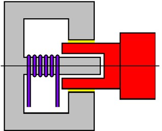
The scheme of the proposed bearing is depicted in Fig. 1. The bearing housing consists of a cylindrical part that forms a bushing of the hydrodynamic bearing and of a cylindrical pin. The rotor journal is hollow, made of non-ferromagnetic material, and is inserted into the hole of the bearing bushing. The gap between the bushing and the rotor journal is filled with the magnetically sensitive oil. The electric coil is mounted on the pin. The coil generates magnetic flux passing through the pin, the cylindrical part of the bearing, the oil layer, and returns back to the pin through the rotor journal. As the resistance against the flow of the lubricant depends on magnetic induction, the change of the current changes the bearing force. As the rotor journal is not magnetic, it is not attracted to the bearing bushing.
Fig. 1A schematic diagram of the bearing
The pressure distribution in the bearing gap is described by the modified Reynolds equation, which has been derived on the following assumptions:
– the oil layer is divided in the sublayers in the radial direction,
– the liquid in each sublayer behaves as Newtonian,
– the applied boundary conditions require that the velocity and the shear stress at location of the contact of two neighboring sublayers are the same,
– the apparent viscosity in the individual sublayers is constant in radial but can vary in the circumferential direction and is determined from the flow curve for the average sublayer velocity rate.
The modified Reynolds equation is nonlinear because the velocity rate needed for assigning viscosity to each oil sublayer depends on the pressure distribution.
In cavitation areas it is assumed that pressure on the medium remains constant and equal to the pressure in the ambient space. Components of the hydraulic forces acting on the rotor journal are calculated by integration of the pressure profile along the length and around the circumference of the bearing.
The bearing housing is considered to be consisted of a set of meridian segments and each segment as a divided core of an electromagnet. Magnetic induction in the lubricating layer is calculated by application of the Hopkinson law. The magnetic reluctance of the part of the magnetic circuit corresponding to the pin and to the cylindrical part of the bearing housing is much lower than that related to the gap between the bearing bushing and the pin, as materials of this part of the magnetic circuit are not ferromagnetic. Therefore, magnetic reluctance of the pin and the cylindrical part of the bearing is neglected. The width of the bearing gap filled with the lubricant and the width of the gap between the pin and the inner surface of the hollow rotor journal are much lower than is the width of gap between the bearing bushing and the pin. Therefore, the influence of the displacement of the journal relative to the bearing bushing on magnetic flux in the magnetic circuit is neglected.
3. Computational simulations
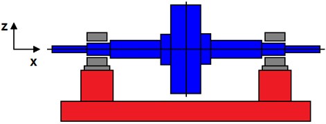
The investigated rotor is rigid. Its scheme can be seen in Fig. 2. At both its end it is coupled with the stationary part by the hydrodynamic bearings lubricated by the ferromagnetic fluid based magnetorheological oil. Each bearing consists of two segments separated by deep grooves, by which the lubricant is supplied in the bearing gap. The rotor turns at constant angular speed, is loaded by it weight, by a constant technological force acting on the rotor in the vertical direction, and is excited by the disc unbalance.
Fig. 2A schematic diagram of the investigated rotor
The rotor was considered as absolutely rigid, the bearings as long and in the computational model they were represented by nonlinear hydraulic forces. Because of the system symmetry, the rotor lateral vibration is governed by a set of two nonlinear motion equations:
where is the rotor mass, is the external damping coefficient, is the eccentricity of the rotor unbalance, is the gravity acceleration, , are the and components of the hydraulic force acting on the rotor, is the technological force, , are the displacements of the rotor center in the horizontal and vertical directions, is the angle of the rotor angular position, and (.), (..) denote the first and second derivatives with respect to time.
The Euler method was applied to solve the motion equations.
The principle technological parameters of the analyzed rotor system are: the rotor mass 430 kg, the coefficient of the rotor linear damping caused by the environment 5 Ns/m, the stationary technological force loading the rotor in the vertical direction 15 kN, the eccentricity of the rotor centre of gravity 50 μm, the bearing length/diameter 60/60 mm, the width of the bearing gap 0.2 mm, the oil dynamic viscosity not effected by a magnetic field 0.06 Pas, and the number of the coil turns 900. The relations for determination of the yielding shear stress and the corresponding oil material parameters were taken from [8].
The task was to analyse the rotor vibration for rising magnitude of the applied current.
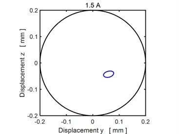
Figs. 3-4 show the steady state orbits of the rotor journal for three magnitudes of the applied current. In all cases the trajectory is a closed curve, which implies the vibration is periodic. The results show that rising current shifts the orbit towards the bearing centre, which means the rising current increases the bearing load capacity.
Fig. 3The steady state orbit of the rotor journal (current 0.0 A)
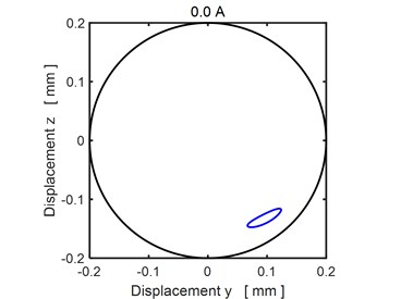
Fig. 4The steady state orbit of the rotor journal: a)1.5 A, b) 2.0 A
a)
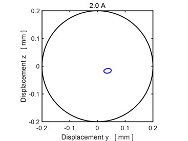
b)
The presence of a magnetic field changes properties of the lubricant. Table 1 shows the magnetic induction in the bearing gap for several magnitudes of the applied current and corresponding values of the yielding shear stress of the lubricant.
Table 1Physical parameters of the lubricant
Current [A] | Magnetic induction [T] | Yielding stress [kPa] | |
1 | 0.0 | 0.00 | 0.00 |
2 | 1.5 | 0.16 | 8.94 |
3 | 2.0 | 0.22 | 21.00 |
In Fig. 5 there are depicted Fourier transforms of the time history of the rotor center displacement in the horizontal direction for two magnitudes of the applied current. The results show two dominant frequencies corresponding the first and second multiple of the excitation frequency. No subharmonic component is present, which means, the vibration excited by the rotor unbalance is stable even if the orbits approach by rising current to the bearing center.
Fig. 5Fourier transform
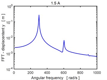
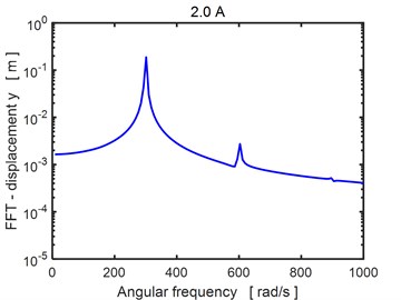
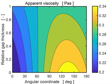
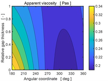
Fig. 6 shows the distribution of the apparent viscosity in the bearing gap at the end of the investigated period. It is evident the viscosity changes both in the circumferential and radial directions. The left figure corresponds to the upper bearing segment, right to the lower one. The magnetic field induces the yielding shear stress, which increases the apparent viscosity about 3-6 times relative to the conditions when no magnetic field is applied.
Fig. 6Distribution of apparent viscosity in the bearing gap for the applied current 1.5 A
4. Conclusions
The principle objective of this study was investigation of the possibilities of application of ferromagnetic fluids as lubricants in hydrodynamic bearings supporting rotors to control their vibration. This paper deals with the design variant when the ferromagnetic fluid is used as a carrying liquid of a magnetorheological oil. The developed mathematical model of the ferromagnetic fluid based magnetorheological bearing was applied to investigate the effect of increasing magnitude of the applied current (increasing magnitude of the magnetic field in the bearing gap) on vibration of rigid rotors. The results show that the rising current increases the load capacity of the bearing and keeps stability of the rotor forced vibration at sufficiently high level. The research contributed to learning more on behavior of rotors mounted in hydrodynamic bearings lubricated by magnetically sensitive lubricants.
References
-
Zapoměl J., Ferfecki Kozánek P. J. Determination of the transient vibrations of a rigid rotor attenuated by a semiactive magnetorheological damping device by means of computational modelling. Applied and Computational Mechanics, Vol. 7, 2013, p. 223-234.
-
Hesselbach J., Abel Keilhack C. Active hydrostatic bearing with magnetorheological fluid. Journal of Applied Physics, Vol. 93, 2003, p. 8441-8443.
-
Guldbakke J. M., Hesselbach J. Development of bearings and a damper based on magnetically controllable fluids. Journal of Physics: Condensed Matter, Vol. 18, 2006, p. 2959-2972.
-
Wang X., Li H., Li M., Bai H., Meng G., Zhang H. Dynamic characteristics of magnetorheological fluid lubricated journal bearing and its application to rotor vibration control. Journal of Vibroengineering, Vol. 17, 2015, p. 1912-1927.
-
Wang X., Li H., Meng G. Rotordynamic coefficients of a controllable magnetorheological fluid lubricated floating ring bearing. Tribology International, Vol. 114, 2017, p. 1-14.
-
Urreta H., Leicht Z., Sanchez A., Agirre A., Kuzhir P., Magnac G. Hydrodynamic bearing lubricated with magnetic fluids. Journal of Intelligent Material Systems and Structures, Vol. 149, 2010, p. 012113.
-
Susan Resiga D., Vékás L. Yield stress and flow behavior of concentrated ferrofluid-based magnetorheological fluids: the influence of composition. Rheologica Acta, Vol. 53, 2014, p. 645-653.
-
Susan Resiga D., Vékás L. From high magnetization ferrofluids to nano-micro composite magnetorheological fluidf: properties and applications. Romanian Reports in Physics, Vol. 70, 2018, p. 1-29.
Cited by
About this article

This work was supported by the Czech Science Foundation (grant project 19-06666S) and by the Ministry of Education, Youth and Sports within the National Programme of Sustainability (NPU II, project LQ1602 - IT4Innovations excellence in science).
