Abstract
Due to the compressibility of gas, the aerodynamic bearings supported rotor system has strong nonlinearity. In this paper, the finite difference method is adopted to solve the Reynolds equation of the compressible fluid and obtain the forces of the gas film. Then the dynamic model of the aerodynamic bearing-rotor system is established, and the Runge-Kutta method is applied to solve the nonlinear equations of motion. With theories of nonlinear dynamics, the bifurcation characteristics of the rotor system supported by aerodynamic bearings are studied. Results show that the rotational speed and the unbalance has great influence on the nonlinear characteristics of the rotor, both periodic and non-periodic responses might emerge.
1. Introduction
Compared with traditional lubrication methods, aerodynamic bearings are widely used in ultra-precision machinery and small, high-speed turbo-machinery due to their advantages of no pollution, low noise, high precision, no mechanical contact, and no friction.
In the 1960s, Lund [1] applied the linear perturbation method to solve the dynamic Reynolds equation. In the 1990s, Czolczynski and Krzysztof [2] applied the Hopf bifurcation to study the stability of the aerodynamic bearing-rotor system. Also, the influencing parameters of the Hopf bifurcation were studied. Based on the linear perturbation theory, Wang [3] obtained the perturbation equation thus the stiffness and damping coefficients of the aerodynamic bearing. Wang et al. [4] combined the finite difference method and the SOR method to solve the Reynolds equation and obtained the spatial distribution of pressure. Then studies on nonlinear bifurcation behavior of the model were carried out. Kang et al. [5] established the dynamic model of the aerodynamic bearing-Jeffcott rotor system. The Galerkin method was used to approximate the unsteady Reynolds equation thus studying the long-term behavior of the rotor system. Bou-Saïd et al. and Ertas et al. [6-7] studied the influences of synchronous response on damping aerodynamic bearing. Kim et al. [8-9] studied the dynamic characteristics of aerodynamic bearing-rotor system with eccentricity considered. The optimum operating condition was proposed by orbit analysis. By direct numerical integration, Miller and Woodruff [10] combined the Reynolds equation and the dynamic equation of the rotor to study the nonlinear characteristics of an aerodynamic bearing-rotor system. Similar to Kim et al. [8-9], Piekos and Breuer [11] also studied the stable operating speed range and nonlinear dynamic characteristics of the rotor system by orbit analysis. Savoulides et al. [12] used the high-order slip model to obtain the stiffness and damping coefficient of the aerodynamic bearing. The results showed that the static pressure bearing is suitable for low-speed machine, and the aerodynamic bearing is more suitable for high-speed rotor system.
In this paper, nonlinear dynamic model of the aerodynamic bearing supported Jeffcott rotor system was established. The finite difference method was applied to solve the unsteady Reynolds equation of the aerodynamic bearing, and the Runge-Kutta method was used to solve the motion equation of motion of the rotor system. The Reynolds equation was iterated in each integration time step to obtain the nonlinear force of the gas film. Finally, the dynamic behavior of the system was studied by nonlinear dynamic theory.
2. Modeling
2.1. Nonlinear force of the aerodynamic bearing
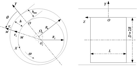
Schematic diagram of the aerodynamic bearing is illustrated in Fig. 1. The Reynolds equation is the basis of aerodynamic bearing studies. Based on the characteristics of aerodynamic bearings, following assumptions are made in the subsequent derivation of Reynolds equation:
(1) The curvature of the fluid film can be ignored.
(2) The pressure variation in radial direction can be ignored.
(3) The air flow is laminar and the inertial force and body force of the air can be ignored.
(4) There is no relative sliding between the air and the journal.
(5) The work medium is a Newtonian fluid, and the influence of temperature can be ignored.
Fig. 1Schematic diagram of the aerodynamic bearing
Based on the above assumptions, the transient Reynolds equation can be obtained by simplifying the N-S equation:
where is the journal radius, is the rotating angle, is time, is the clearance function between the journal and the bearing, is the pressure, is dynamic viscosity of the fluid.
Nondimensionlize Eq. (1):
where , , , and ; – atmospheric pressure, – average radial clearance, – radius of the bearing journal.
Boundary conditions for aerodynamic bearings:
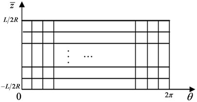
The bearing is virtually cut along the maximum clearance, , to form a rectangular flat area as shown in Fig. 2. In radial and axial direction, the center difference method is adopted. While the implicit difference method is applied in dimension . Then the differentiated Reynolds equation can be written as:
The pressure distribution at time can be obtained by solving Eq. (4) with the SOR-Newton method. Then the nonlinear forces of the aerodynamic bearings can be obtained by the following integration:
Fig. 2Schematic diagram of discretization of the aerodynamic bearing
2.2. Dynamic model of the rotor system
The rotor system supported on aerodynamic bearings is shown in Fig. 3.
Fig. 3Rotor system supported on aerodynamic bearings
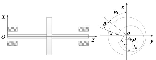
The rotor system constitutes of a single-disc Jeffcott rotor and two aerodynamic bearings at both ends. Nonlinear forces of the aerodynamic bearings are equivalently exerted on the concentrated mass of the shaft. Then the dimensionless equation of motion of the system is:
where , , , , ; and represent the displacement of the bearing journal in and directions, respectively; and represent the displacement of the disc in and directions, respectively; is the rotational speed; is the equivalent stiffness of the Shaft; and are the damping coefficients of the disc and the bearings; is eccentricity of the disc and represents the acceleration of gravity.
3. Results
The parameters of the rotor system are: 2 kg, 12 kg, 3000 N∙s/m, 1000 N∙s/m, 2.5×10⁷ N/m. Radius of the bearing 30 mm. The average radial clearance 37.5×10⁻³ mm. Dynamic viscosity of the fluid 2.82×10⁻⁴ Pa∙s. Length of the bearing 90 mm. Atmospheric pressure 1.01325×10⁵ N/m2.
With these parameters substituted into Eq. (5) and Eq. (6), the influences of rotational speed and unbalance were studied.
3.1. The influence of rotational speed
In order to fully understand the vibration characteristics of the rotor system at different rotational speeds, the rotational speed is used as the bifurcation parameter of the bearing-rotor system. The bifurcation diagram is shown in Fig. 4. The eccentricity of the disc was set to 1.0×10⁻⁶ m, i.e. 1.0×10⁻⁶ m.
Fig. 4Bifurcation diagram
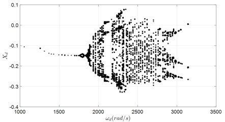
Fig. 5Response of the rotor ω= 1933 rad/s
a) Spectrogram
b) Phase trajectory
c) Poincare map
From the bifurcation diagram, it can be seen that:
(1) Due to the strong nonlinearity of the aerodynamic bearings, the rotor might experience both periodic and non-periodic motion with the increase of rotational speed.
(2) The rotor executes periodic motion when rotational speed smaller than 1730 rad/s.
(3) When 1730 rad/s 2358 rad/s, chaotic motion and multi-periodic motion alternates with each other. With further increasing of the rotational speed, chaotic motion would be dominant until about 3000 rad/s, from which the transformation to period 3 starts.
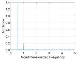
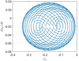
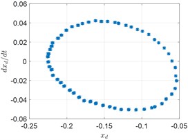
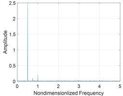
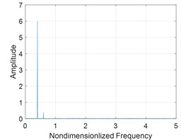
Fig. 5, Fig. 6 and Fig. 7 show the spectrum, phase trajectory and the Poincare mapat different rotational speeds, respectively. It can be seen that there are quasi-periodic, chaotic and multi-period motion states in the rotor system supported by the aerodynamic bearings. Beside the unbalance frequency, both super and sub harmonics can also be observed in the spectrum.
Fig. 6Response of the rotor ω= 2272 rad/s
a) Spectrogram
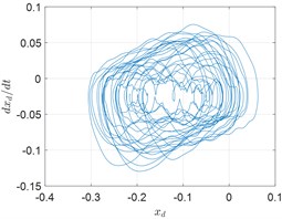
b) Phase trajectory
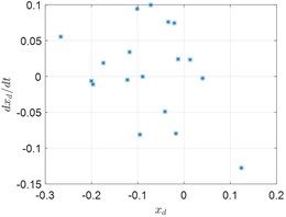
c) Poincare map
Fig. 7Response of the rotor ω= 3050 rad/s
a) Spectrogram
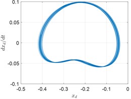
b) Phase trajectory
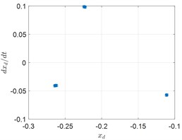
c) Poincare map
3.2. The influence of unbalance
In order to analyze the influences of the unbalance, rotational speed of the rotor is set to 2618 rad/s. Then eccentricity of the disc is used as the bifurcation parameter to plot the bifurcation diagram of the rotor system, as shown in Fig. 8. It can be seen from the bifurcation diagram that the rotor might execute periodic, multi-periodic and chaotic motion under different unbalances.
Fig. 8Bifurcation diagram
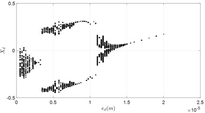
Under small unbalance, the bifurcation diagram shows that system is in non-periodic motion state. However, slight increasing of the unbalance would lead to the transformation to period 1 and period 2 motion. When 3.5×10⁻⁶ m, the bifurcation starts, and the rotor executes chaotic motion. Then period 2 motion would emerge with further increasing of the unbalance, 8×10⁻⁶ m. However, the rotor would re-enter chaotic state when 11.0×10⁻⁶ m until 15.0×10⁻⁶ m. After which the rotor system would execute stable period 1 motion.
4. Conclusions
The finite difference method is adopted to solve the transient Reynolds equation to obtain the nonlinear forces of the aerodynamic bearings. Then the nonlinear equations of motion of the rotor supported by aerodynamic bearings are solved to study the influences of rotational speed and unbalance. The results show that:
1) The rotor would execute stable periodic motion under relatively low speed. The unstable state would emerge with the increasing of the rotational speed. Also, the nonlinear effect of the aerodynamic bearings increases with the rotational speed, accompanied by half-speed whirling.
2) The rotor alternates between periodic and non-periodic motion with the increase of unbalance. Proper increasing of the unbalance can also be applied to suppress the nonlinearity of the aerodynamic bearings.
References
-
J. W. Lund, “Calculation of stiffness and damping properties of gas bearings,” Journal of Lubrication Technology, Vol. 90, No. 4, pp. 793–803, Oct. 1968, https://doi.org/10.1115/1.3601723
-
K. Czolczynski and T. Kapitaniak, “Hopf bifurcation in rotors supported in gas bearings,” Chaos Solutions and Fractals, Vol. 8, No. 4, pp. 499–515, 1997, https://doi.org/10.1016/s0960-0779(96)00110-5
-
Y. F. Wang, “Research on high speed stability of gas floating ring hydrodynamic and hydrostatic hybrid bearings,” (in Chinese), Beihang University, Beijing, China, 1989.
-
C.-C. Wang, M.-J. Jang, and C.-K. Chen, “Non-linear dynamic analysis of a flexible rotor supported by self-acting gas journal bearings,” Proceedings of the Institution of Mechanical Engineers, Part C: Journal of Mechanical Engineering Science, Vol. 218, No. 12, pp. 1527–1538, Dec. 2004, https://doi.org/10.1243/0954406042690407
-
W. Kang, J. Z. Zhang, Y. Liu, and S. Ren, “Stability and bifurcation of symmetrical rotor in self-acting gas journal bearings,” Journal of Aerospace Power, Vol. 22, No. 9, pp. 1537–1543, 2007, https://doi.org/10.13224/j.cnki.jasp.2007.09.019
-
B. Bou-Saïd, G. Grau, and I. Iordanoff, “On nonlinear rotor dynamic effects of aerodynamic bearings with simple flexible rotors,” Journal of Engineering for Gas Turbines and Power, Vol. 130, No. 1, pp. 12503–12512, Jan. 2008, https://doi.org/10.1115/1.2747262
-
B. H. Ertas, M. Camatti, and G. Mariotti, “Synchronous response to rotor imbalance using a damped gas bearing,” Journal of Engineering for Gas Turbines and Power, Vol. 132, No. 3, pp. 32501–32010, Mar. 2010, https://doi.org/10.1115/1.3157097
-
D. Kim, S. Lee, M. D. Bryant, and F. F. Ling, “Hydrodynamic performance of gas microbearings,” Journal of Tribology, Vol. 126, No. 4, pp. 711–718, Oct. 2004, https://doi.org/10.1115/1.1792676
-
D. Kim, “Design and fabrication of sub-millimeter scale gas bearings with tungsten-containing diamond like carbon coatings,” The University of Texas at Austin, 2004.
-
B. A. Miller and I. Green, “Numerical formulation for the dynamic analysis of spiral-grooved gas face seals,” Journal of Tribology, Vol. 123, No. 2, pp. 395–403, Apr. 2001, https://doi.org/10.1115/1.1308015
-
E. S. Piekos and K. S. Breuer, “Pseudospectral orbit simulation of nonideal gas-lubricated journal bearings for microfabricated turbomachines,” Journal of Tribology, Vol. 121, No. 3, pp. 604–609, Jul. 1999, https://doi.org/10.1115/1.2834110
-
N. Savoulides, K. S. Breuer, S. Jacobson, and F. F. Ehrich, “Low-order models for very short hybrid gas bearings,” Journal of Tribology, Vol. 123, No. 2, pp. 368–375, Apr. 2001, https://doi.org/10.1115/1.1308000
About this article

Funding from the Aero Science Foundation of China (Grant No. 201928056001) is gratefully acknowledged. Funding from Project 1912 is gratefully acknowledged.
