Abstract
A general methodology for dynamic modeling and analysis of deep groove ball bearing used in the crank-slider mechanism of punching machine is presented in this paper. The time-varying loads applied at the inner ring of this bearing can be obtained by analyzing the planar multibody systems. The bearing joint has been modeled by introducing a nonlinear constraint force system, which takes into account the contact stiffness interaction between the rolling elements and the raceways. The four-degree-of-freedom dynamic equations for the inner and outer rings of the bearings is established by Newton's second law. By numerical calculation, the variations of the load, trajectory, FFT frequency domain response, and direction phase trajectory and Poincare of the inner ring, and the contact force on each ball element are discussed. The results indicate that the present methodology can not only be used to analyze the overall dynamic behavior of crank-slider mechanism and the deep groove ball bearing used in punching machine, but also to obtain the dynamic loads of the inner ring and ball in bearing. Therefore, the dynamic loads on ball elements can provide a basis for the strength checking, fatigue life calculation and wear analysis of the deep groove ball bearing.
1. Introduction
The crank-slider mechanism is a typical mechanism widely used in internal combustion engines, air compressors, grinding machines and other machines. The connecting pins, which is subjected to large radial loads and high-frequency movements, are one of the key components of the crank-slider mechanism. In order to ensure the strength of the connecting pin, reduce friction and wear during its working process, deep groove ball bearings are usually used as the support parts. Thus, the bearings will bear periodic variable loads, which will produce vibration and noise during high-speed operation.
Therefore, the study of bearing vibration characteristics has been widely concerned by scholars at home and abroad. Yu [1] established a multi-degree-of-freedom model of bearing system and analyzed the influence of factors such as waviness wave number on bearing vibration characteristics. Li [2] established a multi-degree-of-freedom deep groove ball bearing system and studied the effects of sliding characteristics and time-varying loads on bearing vibration. Jain [3] studied the effect of radial clearance on the nonlinear vibration characteristics of the bearing system. Kong [4] investigated the vibration response of the bearing system to the extra contact force generated by local defects of the bearing. Xu [5] presented a general methodology for dynamic modeling and analysis of planar multibody system containing deep groove ball bearing with clearance, and obtained the multibody contact dynamics response characteristics of the ball bearing by calculation.
From the existing literatures, it can be seen that the load used in the dynamics analysis system of rolling bearings is an hypothetical static load or dynamic load, thus, there is a great deviation between the research results and the actual situation, and it is difficult to characterize the actual performance of the bearing. In order to solve the above problems, the author puts forward a new idea based on the deep groove ball bearing used in the crank-slider mechanism of punching machine. This paper is organized as follows. Section 2 introduces the method of obtaining time-varying external load on inner ring of deep groove ball bearing. In Section 3, a brief discussion of the dynamic for deep groove ball bearing is presented. In Section 4, numerical results for presented methods are obtained and discussed. Finally, the conclusions are presented in Section 5.
2. Time-varying external loads on the inner ring of deep groove ball bearing
Fig. 1 is the schematic diagram of the crank slider mechanism of a punching machine. The slider is located right below the fixed hinge , and is subjected to upward stamping resistance . The center of mass and relative position of each component are shown in Fig. 1.
Fig. 1Sketch of crank-slider mechanism of punching machine
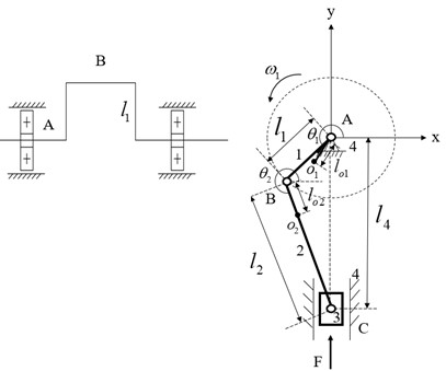
In the coordinate system shown in Fig. 1, force analysis is carried out on the three moving members, and their force equilibrium equations in the x and y directions and moment balance equations of rotation around the center of mass are established. The integrated mechanism dynamic equation can be expressed as:
where, and are components of the support reaction force of member on member (, 1, 2, 3, 4) in and direction, respectively. (1, 2, 3) is the mass of member . and are the angular acceleration of the crank and the connecting rod, respectively. is the acceleration of the slider. and arecomponents of the acceleration of the center of mass of element in and direction, respectively. and are the rotational inertias of the crank and the connecting rod, respectively. is the coefficient, , , , , . The meaning of each symbol is shown in Fig. 1.
By solving Eq. (1), the change law of the support reaction force at hinge A can be obtained. Thus, the time-varying external load on the bearing inner ring is periodically variable in a movement cycle, the bearing will inevitably produce strong vibration.
3. Dynamic equations for deep groove ball bearing
3.1. Bearing system model and dynamic equations
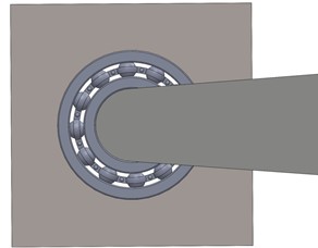
Taking the deep groove ball bearing used in the fixed hinge A for an example, the bearing structure is shown in Fig. 2. The contacts among the ball, the inner and outer races are simplified as a spring-mass system, as shown in Fig. 2.
Fig. 2Sketch of crank-slider mechanism of press machine
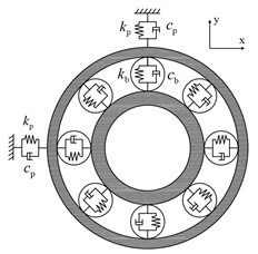
According to the bearing system model shown in Fig. 2, the corresponding dynamic equations in and directions can be expressed as:
where, and are the equivalent mass of the inner and outer races, respectively. and are the damping and stiffness coefficients between the bearing outer race and housing. and are components of the radial contact force among the ball, inner ring and outer races in the and direction, respectively. and are components of the damping force between the inner and outer races in x and y direction, respectively. is calculated as:
where, is the mass of the bearing inner race, is the mass of the crankpin.
3.2. Contact force
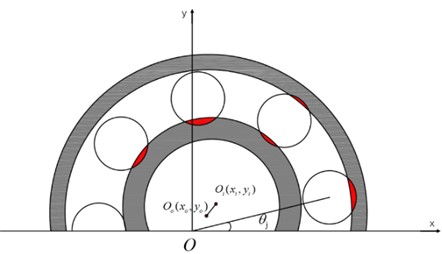
The bearing inner and outer rings will produce relative displacement in the working process. Their position relationship is shown in Fig. 3. According to the local contact Hertzian theory, the load-deformation relation for point contact between ball-raceways for the ball j can be written as follows:
where, is the total contact stiffness coefficient among the ball, inner and outer raceways contacts. is the total deformation of the ball . The subscript "+" indicates that when is greater than zero, the ball is loaded giving rise to a restoring force . If is smaller or equal zero, the restoring force is set to zero. can be computed as:
where, and are the stiffness coefficients of inner and outer races, can be obtained using [6].
can be computed as:
where is the initial angle of balls, here . is the angular velocity of the pin. and are the curvature radius of inner and outer raceway, respectively. and are the center of the inner and outer races, respectively. is the initial radial clearance of bearing. is the angular position for the ball , and can be defined by the following relation:
where is the number of balls in bearing.
Fig. 3Bearing inner and outer ring position relationship
The total restoring force along the and direction is the sum of the restoring forces from each of the rolling elements, and can be defined by the following relation:
3.3. Damping force
The components of the damping force in and direction are expressed as:
where, is the damping force of the ball and can be obtained from Eq. (10):
where is the damping coefficient, 0.25×10⁻⁵×, is the relative velocity of the inner and outer rings.
4. Example
The crank-slider mechanism using in a punching machine is chosen as an example. The length, mass, rotate speed, and moment of inertia of crank are 6 mm, 0.3567 kg, 500 rpm, and 611.7 kg∙mm2, respectively. The length, mass, and moment of inertia of connecting rod are 100 mm, 2.55 kg, and 7517.545 kg∙mm2, respectively. The mass of slider is 16.7965 kg. The blanking force is 8964.8 N as 237° 267°, other is 0 N. A pair of 6204 deep groove ball bearings exist between the crank 1 and the frame 4. The bearing parameters are obtained using [4].
Fig. 4 shows the load curve of the inner race of bearing. It is observed that the load will rapidly increase, and is much larger than when the slider enters the punching section.
Fig. 4Load curve of the inner race of bearing
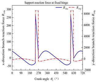
Fig. 5Track curve at the center of the inner race
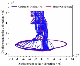
Fig. 5 shows the trajectory curve of the inner race center in a working cycle. It can be seen from Fig. 5 that the track curve of the inner race center is irregular, and has multiple mutations within a working cycle.
Fig. 6 shows the displacement frequency spectrum using the FFT processing. It is observed that the amplitude of vibration response in direction is obviously lower than that in direction.
Fig. 6Inner-loop FFT frequency domain response: a) x-direction, b) y-direction
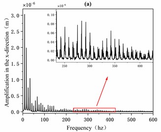
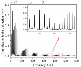
Fig. 7 shows the direction phase trajectory and the Poincaré cross-section mapping points of the inner ring under normal operation. In Fig. 7, the phase trajectories are circular curves of different dimensions. The Poincaré mapping points are distributed in the four parts, indicates that the motion of the inner race is unstable and shows quasi-periodic motion.
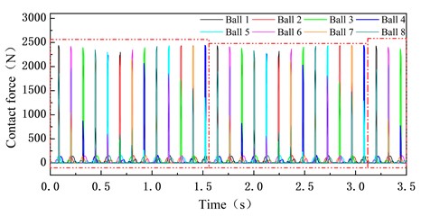
Fig. 8 shows the contact load of balls in two cycle periods during the normal operation. It can be showed that the contact loads of some of the rolling elements will change abruptly, and the impact on a certain point of the inner and outer races of the bearing will increase, and exacerbate the fatigue damage of bearing. Therefore, it can lay the foundation for the fatigue life prediction and the fault diagnosis of bearing.
Fig. 7The phase trajectory and the Poincaré map of the inner race
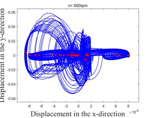
Fig. 8The contact load of ball element
5. Conclusions
A general methodology for dynamic modeling and analysis of deep groove ball bearing used in the crank-slider mechanism of punching machine is presented and discussed throughout this work. A typical deep groove ball bearing 6204 was used as a numerical example, to show the load characteristic of the inner race of bearing and the global dynamic behavior of the system.
From the results obtained, it was demonstrated that the load of the inner race of bearing changed periodically, and increased rapidly when the slider enters the punching section. The method presented can lay the foundation for obtaining the real load of bearing. Obviously, the motion of the inner ring is unstable and shows quasi-periodic motion. The dynamic performance of bearing inner ring in the time-varying load has a strong vibration, the inner ring, rolling body, outer ring, and other components are subjected to strong impact, which will cause the machine to produce noise during the working process and cause environmental pollution. Additionally, the equivalent constraint force on each ball obtained can be used for the strength checking and fatigue life prediction of bearing. The presented methodology provides a theoretic foundation for further research.
References
-
G. W. Yu et al., “Effect of ripple degree wave number on vibration characteristics of deep groove ball bearings (in Chinese),” (in Chinese), Bearings, No. 4, pp. 18–22, 2021.
-
F. Li, X. Li, and D. Shang, “Dynamic modeling and vibration characteristics analysis of deep-groove ball bearing, considering sliding effect,” Mathematics, Vol. 9, No. 19, p. 2408, Sep. 2021, https://doi.org/10.3390/math9192408
-
P. H. Jain and S. P. Bhosle, “Mathematical modeling, simulation and analysis of non-linear vibrations of a ball bearing due to radial clearance and number of balls,” Materials Today: Proceedings, Vol. 72, pp. 927–936, 2023, https://doi.org/10.1016/j.matpr.2022.09.093
-
F. Kong, W. Huang, Y. Jiang, W. Wang, and X. Zhao, “A vibration model of ball bearings with a localized defect based on the hertzian contact stress distribution,” Shock and Vibration, Vol. 2018, pp. 1–14, 2018, https://doi.org/10.1155/2018/5424875
-
L.-X. Xu, Y.-H. Yang, Y.-G. Li, C.-N. Li, and S.-Y. Wang, “Modeling and analysis of planar multibody systems containing deep groove ball bearing with clearance,” Mechanism and Machine Theory, Vol. 56, pp. 69–88, Oct. 2012, https://doi.org/10.1016/j.mechmachtheory.2012.05.009
-
T. A. Harris and M. N. Kotzalas, Essential Concepts of Bearing Technology. Boca Raton: CRC Press, 2006, https://doi.org/10.1201/9781420006599
About this article

The authors have not disclosed any funding.
The datasets generated during and/or analyzed during the current study are available from the corresponding author on reasonable request.
The authors declare that they have no conflict of interest.
