Abstract
By considering the deep groove ball bearing as the research object, and using Hertzian contact theory and elastic mechanics and geometry, a nonlinear dynamic model is established herein for the study of vibration response of deep groove ball bearings having single defect on surfaces of inner and outer races. The outer race and inner race defect size parameters are introduced into this nonlinear dynamic model, and dynamic models of localized fault on outer race, inner race of rolling element bearing are simulated and analyzed by using Runge-Kutta method. Both simulated and experimental localized fault signals (acceleration signals) are subjected to the same diagnostic techniques; namely time domain waveform comparisons and envelope analysis. Then, the impact characteristic that reflects the fault severity in rolling element bearings is obtained from the time interval between two impact points. The simulating results are in accordance with experimental results, which proves the accuracy and practicality of the models used in engineering application. The characteristic defect frequencies and related harmonics are broadly investigated and presented herein. This proposed model provides theoretical basis for monitoring and fault diagnosis of rolling bears.
1. Introduction
Rolling bearings are widely used in various mechanical systems viz. mechanisms, equipment and machines in industries. The rolling bearings are manufactured using high precision machine tools and pass through the strict quality checks. However, the existence or development of even tiny local defects on the mating surfaces of bearing components in a mechanical system may lead to its catastrophic failure due to progressively increase in defect size through passes of time. So the efficient engineering simulating models of bearing fault need to be built to make further research on fault mechanism and dynamic characteristics, which can provide accurate diagnosis method for detecting bearing fault under different running conditions. Therefore, detection of local defects in their early stages through observations of vibration signals of rolling bearings is essentially a vital issue.
With the development and improvement of the fault diagnosis technology for rolling element bearings, research on the fault diagnosis of rolling bearings has attracted considerable attention, and various new models are being proposed [1]. McFadden and Smith [2] presented a simple model to describe the vibration of the rolling element bearing having single point defect on the inner race under constant radial load. The authors modeled the single point defect as an impulse described by an impulse function. Sassi [3] developed a new application called bearing toolbox to simulate the vibratory response of bearings to the excitations produced by localized defects. Considering the difficulties and disadvantages in detecting the fault signal of rolling bearing with background noise, Lu et al. [4] present a method based on the Duffing oscillator and Hu’s moment invariant for health monitoring. A case study on health monitoring and assessment for rolling bearing demonstrates the effectiveness and accuracy of the proposed models and methods. Moreover, Tadina [5] improved a comprehensive model of a ball bearing to obtain the vibration response due to different sizes of localized defects. In a relatively more realistic simplified model, Choudhury and Tandon [6] considered lumped masses of shaft and housing on the vibration response of the locally defective rolling element bearing. They have assumed linearized bearing stiffness and rectangular pulse shape in their modeling. Baydar and Ball [7] examined whether acoustic signals could be used effectively to detect the various local faults in gearboxes using the smoothed pseudo-Wigner Ville distribution with three types of progressing local faults. Result indicated that acoustic signals are very effective for the early detection of faults.
In addition to, a lot of methods of fault diagnosis flourished in the vibration response of the defective rolling bears. Hong [8] proposed a bearing fault severity measurement method based on the Lempel-Ziv complexity and the continuous wavelet transform. The result indicated that the Lempel-Ziv complexity was proportional (for outer race faults) or inversely proportional (for inner race faults) to fault size (severity) for all rotational speeds. Zhao [9] combined the approximate entropy theory with the Empirical Mode Decomposition (EMD) algorithm. The method to distinguish between the step components and impact components was realized through empirical mode recombination of the components. The existence of double impact phenomenon of rolling bears was further verified, and it was feasible to realize quantitative diagnosis through separation methods. Tomasz Barszcz and Nader Sawalhi [10] introduced the Minimum Entropy Deconvolution (MED) to the machine condition monitoring field to enhance fault detection in rolling element bearings. The results demonstrated that the usage of the MED technique had shown a strong enhancement for both fault detection and diagnosis.
However, the quantitative analysis of faults in rolling bears should be further considered from the aspect of rolling bear defective mechanism. Patil [11] developed a mathematical model for the ball bearing vibrations due to defect on the bearing race. With this model the effect of the defect size and its position have been simulated and also the spectral components have been predicted. But the prediction of the actual amplitudes of vibration is not possible by the model. Singh [12] analyzed the contact force of the rolling element entry and exit of the defect with the explicit finite element method. The finite element model presented in the paper can be used to investigate the vibration characteristics of bearings with more complex defect geometries. Cui et al. [13] established a nonlinear vibration model for fault severity assessment of rolling element bearings for the quantitative fault diagnosis. Meanwhile, the impact characteristic that reflected the fault severity in rolling element bearings was obtained from the time interval between two impact points, which were useful for understanding the vibration response mechanism of rolling element bearings under various degrees of fault severity.
In this paper, the main of this paper is organized as follows. In Section 2, the rolling bear system including the mathematical model, the dynamic equations of system, and the fault model of rolling bears are established based on the relevant knowledge of kinematics and dynamics. In Section 3, we simulated the fault model of rolling bear that we have built, and carry out the experiments under the same fault condition. By comparing the simulation results with the experimental results, it is proved that this model is reasonable and correct for defects lying on the races of bears. In Section 4, the conclusions have been submitted.
2. Mathematical model
To study the rolling element bearing structural vibration characteristics, the rolling element-raceway contact can be considered as a spring mass system, in which the outer race is fixed in a rigid support and the inner race is fixed rigidly with the motor shaft. Elastic deformation between raceways and rolling elements produces a non-linear phenomenon between force and deformation, which is obtained by the Hertzian theory.
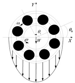
The rolling element bearing is considered as non-linear contact spring as shown in Fig. 1. In the model, the outer race of the bearing is fixed in a rigid support and inner race is held rigidly on the shaft. A constant radial load acts on the bearing. The contact force is calculated using the Hertzian contact deformation theory.
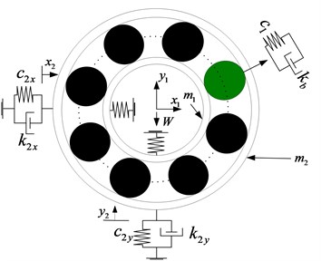
Fig. 1The four-DOF nonlinear dynamic model
2.1. Total deflection of ball in radial direction
According to the Hertzian contact deformation theory, the non-linear relation load-deformation is given by:
where is the load-deflection factor or constant for Hertzian contact elastic deformation, is the radial deflection or contact deformation and the load-deflection exponent; 3/2 for ball bearing and 10/9 for roller bearing. The load-deflection factor depends on the contact geometry.
If is the initial position of the th ball, the angular position at any time is defined by the following relation:
where the angular velocity of cage is expressed in term of angular velocity of shaft and is defined as follows:
If and are the deflections along -axis and -axis and is the internal radial clearance, the radical deflection at the th ball, at any angle is given by . Substituting in Eq. (1), the restoring force can be obtained by:
The springs are required to act only in compression, because the Hertzain forces arise only when there is contact deformation. In other words, the respective spring force comes into play when the instantaneous spring length is shorter than its unstressed length (the term in the bracket should be positive); otherwise the separation between ball and race takes place and the resulting force is set to zero. It has to be noted that the total restoring force is the sum of the restoring forces from each of the rolling elements. By resolving the total restoring force along the -axis and -axis, we obtain:
where and are the components of restoring force in the and directions and is the number of balls, which can be obtained from Table 1.
2.2. Stiffness and damping coefficients at contacts in bearing system
Stiffness and damping coefficients of each component and each contact in a shaft bearing system play significant roles in the vibration study. Thus, precise calculations of values of stiffness and damping are necessary in achieving accuracy in results.
Stiffness coefficients at the contacts formed between races and the th ball are evaluated using the following relations [14]:
In the proposed model, shaft and bearing block damps are assumed to be hysteretic and the equivalent viscous damping coefficient is calculated using the equation as follows [15]:
where is excitation frequency.
2.3. Equations of motion
Based on the relevant knowledge of kinematics and dynamics, dynamic differential equations are as follows:
where respectively represent the mass of inner race and outer race; , , respectively represent the damping factor of the bearing and the damping factor of radial horizontal direction and radial vertical direction of the bearing block; , respectively represent the stiffness factor of radial horizontal direction and radial vertical direction of the rotor; , respectively represent the stiffness factor of radial horizontal direction and radial vertical direction of the bearing block; , , , are the displacement of radial horizontal direction and radial vertical direction of the rotor and bearing block, respectively; is the radial load.
2.4. Fault model of rolling element bearing
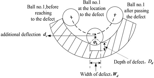
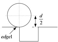
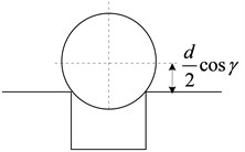
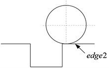
Cracks, pits, and spalls are the most common localized defects of rolling element bearing. In order to describe the characteristic of localized defects, three parameters are introduced including the angular position of the defect the angular of the width of the defect , the depth of the defect and the additional deflection . When the defect occurs on the inner race, the outer race or the rolling element, it changes the contact deformation between the rolling element and the race.
Fig. 2Defect and deflection details
a) Part of the parametric sketch
b) Representation of the deflection due to defect on inner race
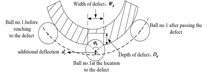
c) Representation of the deflection due to defect on outer race
2.4.1. Defect on the outer race
The local defects on the outer race are normally found in the loaded region of the bearing. Moreover, for the stationary outer race the position of defect does not change with respect to the shaft rotation. The deflection of the th ball varies when it reaches the defective zone of the outer race. Mathematically, the defect is on the surface of the outer race, the radical deformation caused by the defect in the angular position of the th rolling element can be given by:
where is the angular velocity of the shaft and is the initial angular position of the defect. For the defect on the fixed outer race, .
2.4.2. Defect on the inner race
The location of defects on the inner race does not remain stationary since the inner race rotates with the speed of the shaft . The rolling ball approaches the defect either in the loaded zone or the unloaded zone; thus, the deflection of the th ball varies. The defect in the angular position of the th rolling element can be given by:
The angular position of the defect can be given by , for the defect on the inner race, the angular position of the defect changes with the shaft rotating, so the angular position of the defect is a function of time.
2.4.3. Defect on the surface of the rolling element
If the defect is on the surface of the rolling element, it contacts with the inner race and the outer race once per cycle, respectively. For the defect on the th rolling element, the radical deformation caused by the defect can be given by:
where the angular position of the defect on the rolling element , in which the rotating angular velocity , where is the contact angular.
The parameters , are shown in Fig. 2. To simulate the defect on the outer race, the inner race or the rolling element of the rolling bears, the radial deflection caused by the defect is considered to make the bearing clearance increase when the defect contacts with the surface of the bearing components. The increasing radial clearance leads to the Hertzain force between the contact surface decreasing or turning to zero. With the clearance changing, the excitation of the nonlinear time-varying system of the rolling element bearing mutates. To reflect the influence of the defect on the system output, the defect on the races or the rolling element is added to the total deformation of the angular position of the th rolling element. The total deformation can be given by:
Substituting Eq. (12) into Eq. (5), the restoring force of the rolling element bearing can be obtained. Then the dynamic response of failure bearing can be calculated by substituting the restoring force into Eq. (8).
3. Results and discussions
The nonlinear equations are solved to obtain the radial displacements. The inputs used are shown in Table 1. The initial displacements set to the following values: 10-6 m and 10-6 m. The initial accelerations are assumed to be zero: 0 and 0. The input data related to shaft and bearing systems are provided in Table 1. And the Ball Pass Frequency on Outer race (BPFO) and the Ball Pass Frequency on Inner race (BPFI) are calculated as follows with different shaft speed.
When 1750 r/min (where is the shaft speed (r/min)):
104.3 Hz; 158.2 Hz.
When 1772 r/min:
105.6Hz, 160.2 Hz.
Table 1Input data
Deep groove ball bearing | SKF6205 |
Inner race diameter () | 25 mm |
Outer race diameter () | 52 mm |
Pitch diameter () | 39 mm |
Ball diameter () | 8 mm |
Number of balls () | 9 |
Contact angle () | 0° |
Mass of rotor (m) | 5.5 kg |
3.1. Computational procedure
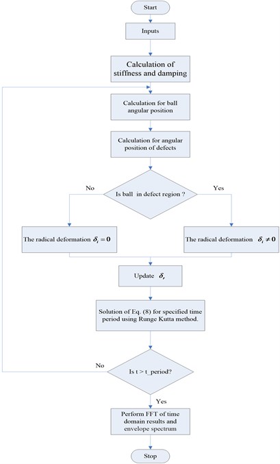
In order to compute the vibration response, the governing equations of motion Eq. (8), relation for the ball positions Eq. (2), and deflection relation Eq. (4), Eq. (5) and Eq. (12) are solved iteratively for each steps of time. Displacements in and direction and and velocities at time are calculated using Eq. (8) by the Runge-Kutta method. The time step for the investigation is assumed as the time required for 0.01° of rotation. The system equations are iteratively solved for specified time period using MATLAB programming. Flow chart for the numerical computation is provided in Fig. 3. The is the simulation time.
Fig. 3The flow chart of numerical computation
3.2. Vibration response of defective bearing
In order to verify the correctness and rationality of the nonlinear dynamic model, experiments are carried out for four different cases, including defect on outer race with shaft speed at 1750 rpm and 1772 rpm, defect on inner race with shaft speed at 1750 rpm 1772 rpm. It has to be noted that the experimental setup is a complex system which contains interaction between different parts of system, particularly defective bearings. Moreover, the defective model is explained in the Fig. 2. The defect’s size at both inner race and outer race for single defect is kept as: depth 11 mils, the width of fault size 7 mils. The defect angle () is kept at 0° for a single defect. The defects are created on races of the test bearings by electric discharge machining. In addition, to assure the validity of the proposed model, a number of simulated results are compared with experimental data. The results of this comparison are reported in the next section. The analytical model developed in this work is a simple model to study the principle features of a defective bearing. It has to be noted here that all vibration response which we plot in next subsection are in horizontal whether in the case of experiments or simulations.
3.2.1. Defect on outer race
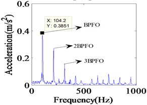
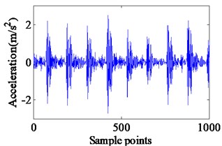
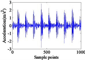
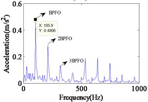
The simulation results of localized outer race faults model at a shaft rotational speed of 1750 rpm are shown in Fig. 4 including the time domain waveform and the envelope spectrum of the vibrations. The impact vibrations caused by the bearing clearance changing can be reflected in the time domain waveform. The defect can only increase the amplitudes of impact vibrations because the vibration frequency of varied flexibility is equal to the failure characteristic frequency of the outer race defect, BBFO and its frequency doubling are clearly reflected in the envelop spectrum. Although the response looks complex, it is still periodic. In the Fig. 4, peaks at the ball pass frequency of outer race BPFO = 104.2 Hz, and its harmonics at 2BPFO, 3BPFO are observed clearly. Fig. 5 illustrates the experimental vibration spectrum with single defect on outer race defect. The experiments are performed at a shaft rotational speed of 1750 rpm. The BPFO peak is found at 105 Hz. The small variation in two frequencies appears due to shaft speed variation.
Fig. 4Simulated vibration response and envelope spectrum in radial X direction with single defect on outer race (Ns= 1750 r/min)
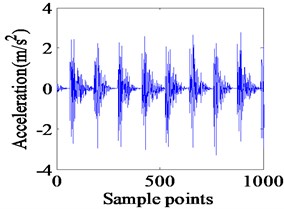
a) Time domain waveform
b) Envelope spectrum
It can be noted that all the frequency components as predicted by the simulated spectrum shown in Fig. 4, and the value of failure characteristic frequency of the outer race defect is almost consistent with the experimental results. In order to further verify the validity of proposed fault model, the simulations and experiments have been carried out with shaft speed at 1772 rpm. The simulated results and experimental results are shown in Fig. 6 and Fig. 7, respectively.
It can be seen from Fig. 7 that the impact vibrations caused by the bearing clearance changing show the same vibration characteristics with the simulation results. In Figs. 6 and 7, the frequency spectrum of experimental data has a peak at 105.9 Hz, and in the frequency response obtained from the proposed model, a peak occurs at 105.5 Hz. Meanwhile, the BBFO and its frequency doubling are also clearly reflected in the envelop spectrum, which is similar to the case of shaft speed at 1750 rpm. In addition, to further demonstrate the validity of the proposed models, we compare the simulation results and the experimental results on the fault characteristic frequencies of outer race. The comparison of characteristic defective frequencies has been listed in Table 2. It can be clearly observed in Table 2 that the simulation results of the proposed model are much closer to the theoretical value than the experimental results whether in the case of 1750 r/min or 1772 r/min. As a result, the comparison of frequency content of simulated model and experimental results confirms the successful modeling of the effect in this analysis.
Fig. 5Experimental vibration response and envelope spectrum in radial X direction with single defect on outer race (Ns= 1750 r/min)
a) Time domain waveform
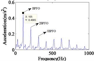
b) Envelope spectrum
Fig. 6Simulated vibration response and envelope spectrum in radial X direction with single defect on outer race (Ns= 1772 r/min)
a) Time domain waveform
b) Envelope spectrum
Fig. 7Experimental vibration response and envelope spectrum in radial X direction with single defect on outer race (Ns= 1772 r/min)
a) Time domain waveform
b) Envelope spectrum
Table 2Comparison of characteristic defective frequencies (on outer race)
1750 r/min | BPFO | 2BPFO | 3BPFO |
Simulated results | 104.2 Hz | 208.4 Hz | 312.6 Hz |
Experimental results | 105 Hz | 210.1 Hz | 315.1 Hz |
Theoretical value | 104.3 Hz | 208.6 Hz | 312.9 Hz |
1772 r/min | BPFO | 2BPFO | 3BPFO |
Simulated results | 105.5 Hz | 210.9 Hz | 316.4 Hz |
Experimental results | 105.9 Hz | 211.8 Hz | 317.7 Hz |
Theoretical value | 105.6 Hz | 211.2 Hz | 316.8 Hz |
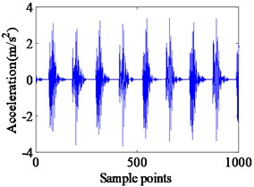
3.2.2. Defect on inner race
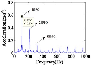
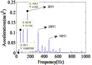
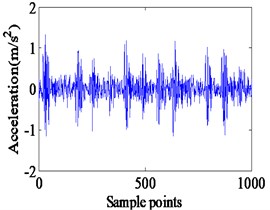
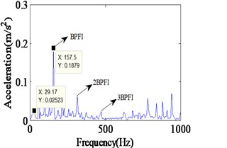
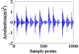
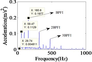
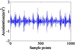
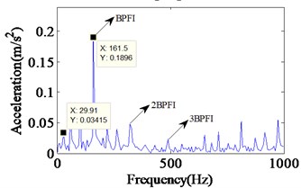
Complicated vibration takes place when the defect lies on the surface of the rotating inner race. It happens due to rotation of both defect and ball. In case of inner race defect, amplitudes of the vibrations are not constant due to varying loadings on ball and defect contacts. The deformation magnitude increases when defect and ball contact occurs in the loaded zone and it decreases in the unloaded zone. A series of impact vibration of varying amplitudes can be found in Fig. 8. The amplitudes of the impact vibrations are modulated by the shaft rotation frequency, because the position of the inner race defect constantly changes with the rotating of the rotor. Moreover, the envelop spectrum shows the rotating frequency and its frequency doubling, along with BPFI and its frequency doubling. The BPFI peak is found at 158.2 Hz, and their harmonics are clearly visible in Fig. 8. And the shaft rotation frequency and its harmonics are observed clearly. During the experimentation, the acceleration of vibration is captured on top of test bearing housing. Fig. 9 illustrates the experimental vibration spectrum with inner race defect in the bearing. The BPFI peaks are found at 157.5 Hz. This small variation in frequency appears due to variation in shaft speed. The shaft frequency of rolling bear is about 26.2 Hz, which is also clearly observed in Figs. 8 and 9.
Fig. 8Vibration response and Envelope spectrum in radial X direction with single defect on inner race (Ns= 1750 r/min)
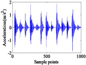
a) Time domain waveform
b) Envelope spectrum
Fig. 9Experimental vibration response and Envelope spectrum in radial X direction with single defect on inner race (Ns= 1750 r/min)
a) Time domain waveform
b) Envelope spectrum
It can be seen that all the frequency components, as predicted by the simulated spectrum shown in Fig. 8, find existence in the experimental spectrum, too. In addition, further simulations and experiments are implemented with the shaft speed at 1772 rpm to test the proposed model. As they can be seen in Figs. 10 and 11, the acceleration response of proposed model and the envelope spectrum included the expected frequencies. The envelope spectrum of experimental data have a peak at 161.5 Hz, and in the frequency response obtained from the proposed model, a peak occurs at 160.6 Hz. Similar with the inner race defect with the shaft speed at 1750 rpm, the envelop spectrum in Fig. 10 shows the rotating frequency and its frequency doubling, along with BPFI and its frequency doubling.
Fig. 10Simulated vibration response and envelope spectrum in radial X direction with single defect on inner race (Ns= 1772 r/min)
a) Time domain waveform
b) Envelope spectrum
Fig. 11Experimental vibration response and envelope spectrum in radial X direction with single defect on inner race (Ns= 1772 r/min)
a) Time domain waveform
b) Envelope spectrum
Moreover, good correlations of simulated and experimental extracted frequencies can be seen in Table 3. It can be found that the BPFI and its harmonics which we simulated are much closer to the theoretical results than the experimental results whether in the case of 1750 rpm or 1772 rpm, which shows the rationality of proposed model. As a result, overall good matching of simulated and experimental results develops good confidence in the proposed dynamic model. But the comparison of simulation results and experimental results shows poor agreement for vibration amplitude at shaft frequency. This is expected due to residual unbalance, misalignment, etc. which has not been considered in theoretical.
Table 3Comparison of characteristic defective frequencies (on inner race)
1750 r/min | BPFI | 2BPFI | 3BPFI |
Simulated results | 158.2 Hz | 316.4 Hz | 474.6 Hz |
Experimental results | 157.5 Hz | 315 Hz | 472.5 Hz |
Theoretical value | 158.2 Hz | 316.4 Hz | 474.6 Hz |
1772 r/min | BPFI | 2BPFI | 3BPFI |
Simulated results | 160.6 Hz | 321.2 Hz | 481.8 Hz |
Experimental results | 161.5 Hz | 323 Hz | 484.5 Hz |
Theoretical value | 160.2 Hz | 320.4 Hz | 480.6 Hz |
3.3. The consistency on the defect size between simulations and experiments
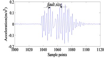
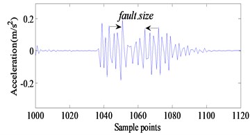
Fig. 12 shows the simulating results of localized outer race faults of the dynamic nonlinear model. The impact vibrations caused by the bearing clearance changing can be reflected in the time domain waveform. The defect on the races or the rolling element is added to the total deformation of the angular position of the th rolling element. The fault model is shown in the Fig. 13. While the rolling element enters and exits the defect, there will be two obvious impact signals because of mutational clearance. The time interval of the two obvious impact signals can reflect the defect size as shown in Fig. 14.
Fig. 12The fault model
a)
b)
c)
Fig. 13Reflection of the defect size
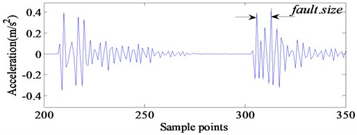
Fig. 14 shows the results of the bearing with defect on its outer race. Compared the experimental data with the simulation results, the fault size is reflected clearly in the time domain waveform. It can be seen in Fig. 14 that, the fault size shown in simulation of propose model and experiment is very close and consistent. This also indicates that the fault dynamic model we have established is correct and reasonable. It has to be noted that there are differences between the amplitudes of vibration predicted by the model and obtained by the experiment because it is difficult to take into account the effects of the total rotor bearing system in the theoretical model. As a result, the consistency of fault size between simulation results and experimental results verifies the validity of the proposed models.
Fig. 14a) Comparison between model simulating results and b) experimental results
a)
b)
4. Conclusions
In this paper, the effect of local surface defects on the dynamic response of a rolling bear system is investigated using an analytical model. The vibration amplitudes and frequencies are simulated by solving coupled equations of motions using the Runge-Kutta method in Matlab.
The main conclusions can be concluded as follow:
1) The simulation results of dynamic model for the outer race defect and the inner race defect indicates that the defect positions can be diagnosed by the characteristic frequency of the vibrations. The frequency spectrum of the bearing vibrations due to the defects comprises mainly BPFO and its harmonics for outer race defect, BPFI and the combination of BPFI and the shaft frequency for the inner race defect. The accordance of the frequency components obtained from the mathematical model with those appeared in the frequency spectrum of the experimental data verifies the validity of the proposed model.
2) The prediction of the actual amplitudes of vibration is not possible by the model because it is difficult to incorporate the effect of the rotor bearing system into the model. However, it helps to predict the effect of the defect position and the spectral components due to this.
3) The good correlations between the numerically simulated and experimental results amply demonstrates that this dynamic model can be used with confidence for the study and prediction of vibrations of defective deep groove ball bearings. Meanwhile the proposed models provide theoretical basis for monitoring and fault diagnosis of rolling element bearing to some extent.
References
-
Feng Z., Liang M., Chu F. Recent advances in time-frequency analysis methods for machinery fault diagnosis: a review with application examples. Mechanical Systems and Signal Processing, Vol. 38, Issue 1, 2013, p. 165-205.
-
McFadden P. D., Smith J. D. Model for the vibration produced by a single point defect in a rolling element bearing. Journal of Sound and Vibration, Vol. 96, 1984, p. 69-82.
-
Sassi S., Badri B., Thomas M. A numerical model to predict damaged bearing vibrations. Journal of Vibration and Control, Vol. 13, Issue 11, 2007, p. 1603-1628.
-
Lu C., Tao L., Fan H., Wang Z. Approach to health monitoring and assessment of rolling bearing. Journal of Vibroengineering, Vol. 15, Issue 2, 2013, p. 747-761.
-
Tadina M., Bolte M., Ar V. Z. Improved model of a ball bearing for the simulation of vibration signals due to faults during run-up. Journal of Sound and Vibration, Vol. 330, Issue 17, 2011, p. 4287-4301.
-
Choudhury A., Tandon N. Vibration response of rolling element bearings in a rotor bearing system to a local defect under radial load. Journal of Tribology, Vol. 128, Issue 2, 2006, p. 252-261.
-
Baydar N., Ball A. A comparative study of acoustic and vibration signals in detection of gear failures using Wigner-Ville distribution. Mechanical Systems and Signal Processing, Vol. 15, Issue 6, 2001, p. 1091-1107.
-
Hong H., Liang M. Fault severity assessment for rolling element bearings using the Lempel-Ziv complexity and continuous wavelet transform. Journal of Sound and Vibration, Vol. 320, Issue 1, 2009, p. 452-468.
-
Zhao S., Liang L., Xu G., Wang J., Zhang W. Quantitative diagnosis of a spall-like fault of a rolling element bearing by empirical mode decomposition and the approximate entropy method. Mechanical Systems and Signal Processing, Vol. 40, Issue 1, 2013, p. 154-177.
-
Tomasz B., Nader S. Fault detection enhancement in rolling element bearings using the minimum entropy deconvolution. Archives of Acoustics, Vol. 37, Issue 2, 2012, p. 131-141.
-
Patil M. S., Mathew J., Rajendrakumar P. K., Desai S. A theoretical model to predict the effect of localized defect on vibrations associated with ball bearing. International Journal of Mechanical Sciences, Vol. 52, Issue 9, 2010, p. 1193-1201.
-
Singh S., Köpke U. G., Howard C. Q., Petersen D. Analyses of contact forces and vibration response for a defective rolling element bearing using an explicit dynamics finite element model. Journal of Sound and Vibration, Vol. 333, Issue 21, 2014, p. 5356-5377.
-
Cui L., Zhang Y., Zhang F., Zhang J., Lee S. Vibration response mechanism of faulty outer race rolling element bearings for quantitative analysis. Journal of Sound and Vibration, Vol. 364, Issue 3, 2016, p. 67-76.
-
Harris T. A. Rolling Bearings Analysis. Third Edition, Wiley, New York, 1991.
-
Genta G. On a persistent misunderstanding of the role of hysteretic damping in rotor dynamics. Journal of Vibration and Acoustics, Vol. 126, Issue 3, 2004, p. 459-461.
About this article

This work was supported by the National Natural Science Foundation of China (Grant No. 51475407), Hebei Provincial Natural Science Foundation of China (No. E2015203190), The Education Department of Hebei Province Outstanding Youth Fund (No. YQ2013020) and Key Project of Natural Science Research in Colleges and Universities of Hebei Province (Grant No. ZD2015050)
