Abstract
The switched reluctance motor drives the rotor based on the principle of minimum reluctance, which is structurally simpler, but the doubly salient structure of the stator and rotor leads to severe torque pulsation. This paper briefly introduces the switched reluctance motor and the auto-disturbance rejection controller for suppressing the torque pulsation of the switched reluctance motor. Then, the auto-disturbance rejection controller was simulated in the MATLAB software, and it was compared with the direct torque control strategy. The results showed that the switched reluctance motor installed with the self-reluctance controller reached the set rotational speed faster, with a smoother torque change; when the set speed changed abruptly, it was adjusted to the new rotational speed faster, with a smooth and stable torque change; when the load torque changed abruptly, it was adjusted to the new torque smoother and faster, and the adjustment to the rotational speed was also faster.
1. Introduction
Traditional fossil energy sources such as oil and coal are non-renewable resources and high-demand industrial raw materials. In addition, traditional fossil energy sources produce a lot of pollution during use, which is not conducive to sustainable development [1]. Electricity is clean, stable, efficient and convenient, and has been used in all aspects of production and life. The electric motor is one of the applications of electric energy. Based on the characteristics of electric energy [2], various loads driven by electric motors produce no pollution and are relatively quiet during use. Switched reluctance motors (SRMs) [3] are a type of electric motor with the advantages of simple structure, high efficiency and high fault tolerance, but in practical use, the large torque pulsation during current communication leads to more noise. In order to improve the performance of SRMs, effective control of torque pulsation is required. Labiod et al. [4] used direct instantaneous torque control (DITC) to reduce SRM torque pulsation. Gupta et al. [5] optimized the number of stator slots/rotor pole arcs for a single-tooth-wound dual-stator SRM and found a 40 % reduction in torque pulsation on the optimized structure through simulation. Zhang et al. [6] proposed a torque pulsation suppression strategy for SRMs with dead-beat current control and active thermal management. Wang et al. [7] proposed a direct instantaneous torque control (DITC) method to control torque pulsation, modulated toque by pulse-width modulation (PWM), and selected the optimal switch signal based on the PWM signal and the sector where the rotor position was located. The simulation results suggested that the compensated PWM-DITC could effectively suppress the torque pulsation of switch reluctance machine. In order to reduce the torque pulsation and improve system dynamic performance, Liu et al. [8] put forward a DITC strategy based on the proportion integration differentiation (PID) controller. The simulation experiment found that the DITC strategy effectively reduced the torque pulsation and the PID controller reduced the overshoot and adjustment time, improving the robustness and anti-interference of the system. Zhang et al. [9] put forward a voltage vector dynamic sorting-based torque control strategy and verified its effectiveness through simulations. This paper briefly introduces the SRM and the auto-disturbance rejection controller used for suppressing the torque pulsation of the SRM. The auto-disturbance rejection controller was simulated in the MATLAB software and compared with the direct torque control strategy.
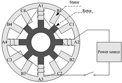
Fig. 1Schematic diagram of SRM
2. Switched reluctance motor
The basic structure of the SRM is shown in Fig. 1, including a stator and a rotor, and it is a common structure of electric motors. The shell of the SRM is the stator, which is raised inward and remains motionless during operation, and the middle structure is the rotor, which is raised outward and rotates around the shaft under the action of electromagnetism during operation [10]. Unlike conventional motors, the SRM structure does not have permanent magnets, and there are no coils wound on the rotor. The salient poles of both the stator and rotor are made of pressed silicon steel sheets, and the coils are wound on the salient pole of the stator [11]. The SRM follows the minimum reluctance principle during operation, i.e., when the winding coil of the stator salient pole was powered on, the stator salient pole will generate a corresponding magnetic field to produce magnetic pull on the surrounding rotor salient pole, making the magnetic resistance between the stator salient pole and rotor salient pole minimum, and the salient pole center lines of the stator and rotor are aligned. Fig. 1 shows a three-phase SRM, which has 12 stator salient poles and 8 rotor salient poles. The number of stator salient poles of every phase is 4, windings between different phases are independent, and the windings of the same phase are connected in series. In Fig. 1, when the winding is powered on according to the sequence of A, B and C, the rotor salient pole will rotate counterclockwise to achieve the minimum magnetic resistance. When the winding is powered on according to the sequence of C, B and A, the rotor will rotate clockwise. The rotation direction of the rotor is related to the sequence of phase energization rather than the current direction in the winding. The mathematical model of the SRM [12] is:
where is the applied voltage of the -th phase winding, is the resistance of the -th phase winding, is the current of the -th phase winding, is time, is the magnetic chain of the -th phase winding, is the inductance of the -th phase winding, which is a function of winding current and rotor position angle , is the electromagnetic torque [13], and are the magnetic co-energy and magnetic storage energy, respectively, and are the total winding current and the total winding chain, respectively, is the rotational inertia, is the friction coefficient, and is the load torque.
3. Torque pulsation control strategy
It is seen from the above description of the mathematical model of the SRM that the SRM operates by cyclically energizing the phase windings in sequence. The energized phase windings produce excitation, which generates tangential magnetic pull on the rotor to achieve the minimum magnetic resistance, during which the rotor generates electromagnetic torque. After offset by the rotor’s rotational inertia and the torque due to friction, actual torque provided by the SRM to the outside is obtained. It is seen from the mathematical model of the SRM that after the structural parameters of the SRM are determined, the provided electromagnetic torque is affected by rotor position angle and winding current . However, in practical applications, the winding current and the inductance affected by the winding current vary nonlinearly, which is easy to produce torque pulsation during current communication to affect the working stability of the SRM.
The torque pulsation during SRM operation can be reduced by optimizing the SRM structure, but the doubly salient pole structure of the SRM determines the inevitable distortion and uneven distribution of the unit flux and density of the relative air gap between the stator and rotor during operation, which leads to the generation of torque pulsation. Therefore, appropriate control strategies are used to reduce the torque pulsation.
3.1. Direct torque control strategy
The torque pulsation during SRM operation can be reduced by optimizing the SRM structure [14], but the doubly salient structure of the SRM determines the inevitable distortion and uneven distribution of the unit flux and density of the relative air gap between the stator and rotor during operation, which leads to the generation of torque pulsation [15]. Therefore, appropriate control strategies are usually used to reduce torque pulsation.
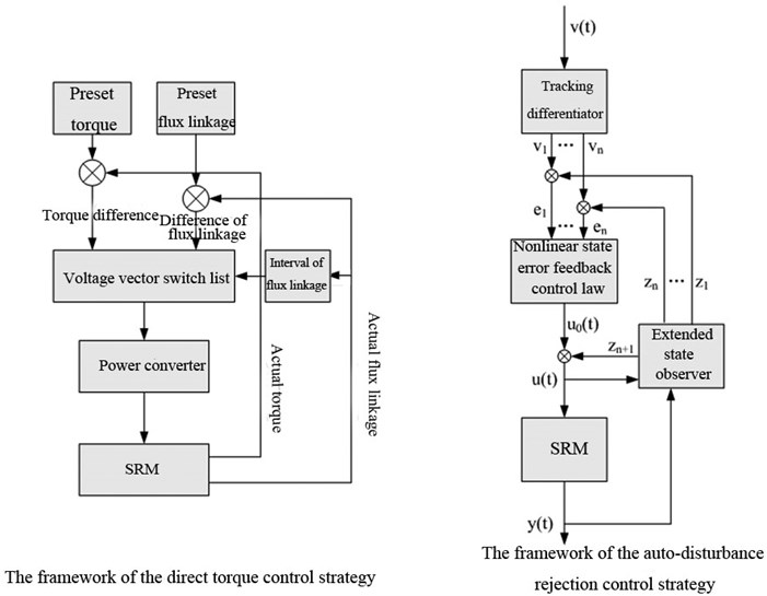
The basic principle of the direct torque control strategy is to monitor the actual torque of the SRM in real-time and compare it with the set torque. The torque is improved if the torque is small and reduced if the torque is large. The control strategy is shown in the left-hand flow frame in Fig. 2.
(1) The set torque and magnetic chain are input, and they are compared with the actual torque and actual flux linkage of the SRM collected by the sensor to obtain the difference value.
(2) The variation requirement of the torque and flux linkage is determined according to the difference value of the torque and the difference value of the flux linkage. If the torque difference value is positive, then it means the set torque is greater than the actual torque and the SRM needs to increase its torque; if the torque difference value is negative, then it means the set torque is smaller than the actual torque and the SRM needs to reduce its torque. The variation requirement of the flux linkage is determined in the same way.
(3) The resultant vector of the current flux linkage is calculated for the flux linkage collected by the sensor, and the sector in which the flux linkage is located is determined based on its phase angle. The calculation formula is:
where , and are the flux linkage of phases A, B, and C, and are the two flux linkages after the transformation of the coordinates of the three-phase flux linkage, and is the phase angle after the three-phase flux linkage vectors are combined into one flux linkage vector.
(4) Voltage vectors are selected from the voltage vector switching table according to the variation requirements of the torque and flux linkage and the resultant vector phase angle of the flux linkage. Every voltage vector represents a three-phase current state.
(5) The power converter regulates the power according to the voltage vector switching table to realize the control of the SRM torque.
Fig. 2Basic framework of direct torque control strategy and auto-disturbance rejection control strategy
3.2. Auto-disturbance rejection control strategy
Auto-disturbance rejection controller develops from the PID control method [16]. The basic control principle of the controller is similar to that of the direct torque control strategy, which is to monitor the actual operating parameters of the SRM in real-time, compare the monitored data with the pre-set values, and adjust the SRM based on the difference. The basic structure of this control strategy is shown in Fig. 2. The control flow is as follows.
(1) The given standard signal is given transition processing using a tracking differentiator (TD), and the differential signal of the tracking signal of the given standard signal is extracted according to the set order [17]. The calculation formula is:
where is the tracking signal for a given standard signal , is the order differential signal of , is the parameter that adjusts the speed of by a TD, is a nonlinear factor, and is the width of the linear interval.
(2) The input and output signals of SRM are observed using extended state observer (ESO) to achieve the estimation of internal state variables and the observation of internal parameters and external disturbance. The processing formula is:
where is the output signal of the SRM, is the tracking signal of the output signal of the SRM, is the order differential signal of the tracking signal, is the feedback gain, is the compensation factor, and is the input signal of the SRM.
(3) The internal and external state signals of the SRM and their order differential signals obtained after ESO processing are compared with the calibration signals and their order differential signals obtained after TD processing, and the differences are calculated. Then, the control signals of the SRM are obtained through processing and calculating the difference values using nonlinear state error feedback control law (NLSEF), and the corresponding equations are:
where is the SRM control signal calculated by NLLSEF, is the SRM control signal after compensating for the internal disturbances of the controller, is the regulation parameter, and is the nonlinear function.
(4) After steps (1), (2) and (3), the SRM control signal regulates the SRM, the output signal of the STM is collected again and processed by steps (1), (2) and (3) to ensure stability of the SRM torque.
4. Simulation experiments
4.1. Experimental environment
Simulation experiments were performed on SRM using MATLAB software [18] in a laboratory server with configurations of the Windows 7 operating system and 16G memory.
4.2. Parameter setting
Simulation experiments were conducted on a 12/8 three-phase SRM, and its basic parameters are shown in Table 1. The main purpose of the simulation experiments on the SRM was to check the suppression effect of the auto-disturbance rejection control method on the SRM torque pulsation; therefore, in order to verify the effectiveness of this control strategy, in addition to the simulation experiments, the direct torque control strategy was also simulated.
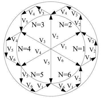
The principle of direct torque control strategy for SRM torque control is to select the appropriate voltage vector according to deviations of the magnetic chain and torque with the set values. Fig. 3 shows a sketch map of the voltage vector selection rule. Table 2 is the corresponding on-off table of voltage vector selection. Finally, the selection of voltage vector is determined not only by the change of the combined torque of the magnetic chain but also the phase angle of the three-phase combined magnetic chain vector. Using the three parameters, the phase angle of the combined magnetic chain, the torque and the combined magnetic chain, the required voltage vector can be queried in Table 2 to achieve torque control.
Table 1Basic parameters of SRM
Parameter name | Numerical value | Parameter name | Numerical value |
Number of stator teeth | 12 | Number of rotor teeth | 8 |
Phase number | 3 | Rotor rotational inertia | 0.0082 kg·m2 |
Friction coefficient | 0.01 N·m·s | Asymmetric inductors | 6.7×10⁻⁴ H |
Symmetrical inductors | 0.0235 H | Saturated symmetrical inductors | 1.5×10⁻⁴ H |
Maximum flux linkage | 0.485 Wb | Motor speed | 500 r/min |
Load torque | 5 N·m | Impressed voltage | 240 V |
Table 2The on-off table of voltage vector
Vector phase angle of combined magnetic chain | Sector number | ||||
1 | |||||
2 | |||||
3 | |||||
4 | |||||
5 | |||||
6 |
The control process of the auto-disturbance rejection control strategy has been described in the previous text and will not be repeated here. TD in the auto-disturbance rejection controller was two-order, then the ESO was three-order. When the self-turbulence controller was used for torque pulsation control, the values of , , , , , and were set, and the other parameters were obtained through detection and calculation. Through orthogonal experiments, the parameters were set as follows: 2000, 0.5, 0.01, 12000, 3.6×10⁷ and 2000.
Fig. 3The sketch map of the voltage vector selection rule
4.3. Working condition setting
Working condition 1: The rotor speed of SRM was set as 300 r/m, the applied voltage was set as 240 V, and the load torque was set as 5 N·m.
Working condition 2: The impressed voltage of SRM was set as 240 V, the load torque was set as 5 N·m, the initial rotor speed was set as 300 r/min, and the rotor speed was set as 450 r/min at 0.3 s.
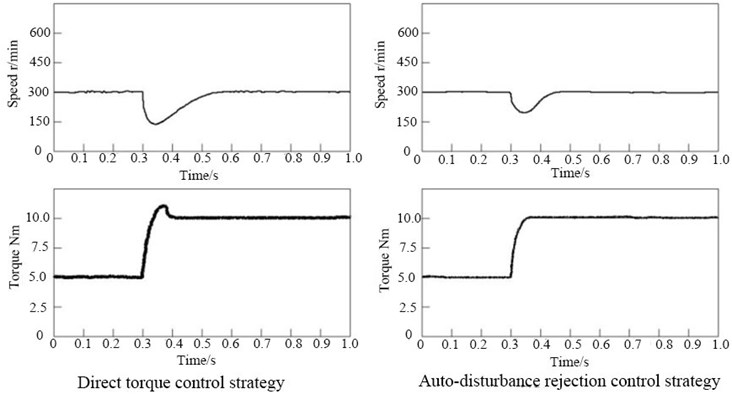
Working condition 3: The impressed voltage of SRM was set as 240 V, the rotor speed was set as 300 r/min, the initial load torque was set as 5 N·m, and the load torque was set as 10 N·m at 0.3 s.
4.4. Simulation results
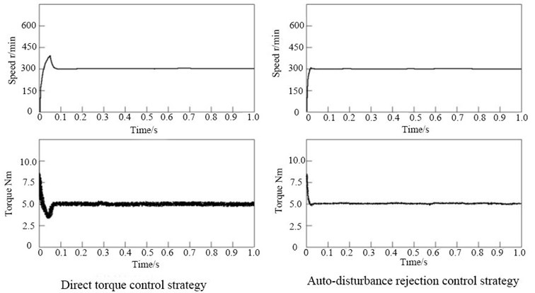
Working condition 1 was a simulation of the SRM start-up, and the rotational speed and torque variation of the SRM under the two control strategies are shown in Fig. 4. The rotational speed of the SRM under both control strategies was finally stabilized at 300 r/min, and the overall torque fluctuated around 5 N·m. The SRM under the auto-disturbance rejection controller reached the set speed faster and had less torque pulsation, while the SRM under the direct torque control strategy not only had slower speed regulation and larger torque pulsation but also had an obvious overshoot phenomenon.
Fig. 4Variations of speed and torque under two control strategies in working condition 1
Working condition 2 was a simulation of the sudden change of the preset speed. The speed and torque variations of the SRM under both control strategies in working condition 2 are shown in Fig. 5. In terms of speed, the SRM under both control strategies eventually stabilized at 450 r/min, but the speed variation was faster and smoother under the auto-disturbance rejection controller, and the speed variation was relatively slow and the overshoot phenomenon was obvious under the direct torque control strategy. In terms of torque, the SRM under both control strategies experienced a sudden increase in torque and then a decrease in torque. The SRM torque under the auto-disturbance rejection controller eventually dropped smoothly back to 5 N·m, while the torque had overshoot when decreasing under the direct torque control strategy, with more obvious pulsation.
Working condition 3 is a simulation of the sudden change of the load torque. The speed and torque variations of the SRM under both control strategies in working condition 2 are shown in Fig. 6. In terms of speed, the speed of the SRM under the two strategies suddenly decreased when the load torque suddenly increased; the speed under the direct control strategy decreased more and gradually returned to the original speed, but the returning speed was slower than the auto-disturbance rejection controller. In terms of torque, when the load torque increased, the torque under the two strategies also increased. The SRM under the auto-disturbance rejection strategy had a smoother torque change, while the SRM under the direct torque control strategy not only pulsated more significantly but also had an overshoot when adjusting the torque.
Fig. 5Variations of speed and torque under two control strategies in working condition 2
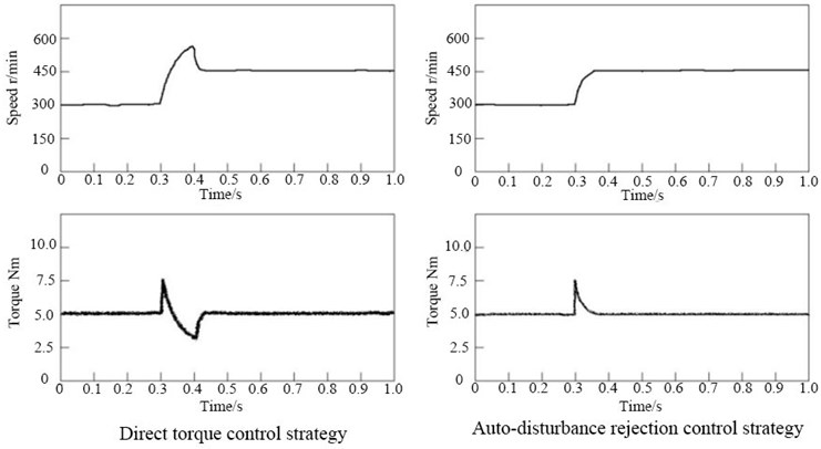
Fig. 6Variations of speed and torque under two control strategies in working condition 3
5. Discussion
This paper proposed two control strategies: direct torque control, which monitors the torque and magnetic chain of the SRM, and then uses a voltage vector switching table to control the torque of the SRM directly according to variations of torque and magnetic chain, and auto-disturbance torque control, which uses PID to control the torque of the SRM according to the difference between the actual torque and the set torque of the SRM. After that, the two control strategies were simulated and compared by letting the two control strategies working in three working conditions. The final results are shown above.
In working condition 1, the rotor rotational speed and load torque were set to test rotational speed and torque variations under the two control strategies when the SRM started. In working condition 2, i.e., the rotational speed increased suddenly under the stable rotational speed and torque, changes in the rotational speed and torque under the two control strategies were tested. In working condition 2, i.e., the load torque increased suddenly under the stable rotational speed and torque, changes in the rotational speed and torque under the two control strategies were tested. The final results demonstrated that the rotational speed and torque remained stable under the two control strategies when the SRM operated stably regardless of the working condition, but the disturbance to the rotational speed and torque was smaller under the auto-disturbance control strategy. In working condition 1, in the startup process, the SRM that adopted the auto-disturbance control strategy could not only reach the set rotational sped and torque faster but also nearly had no overshoot; the SRM that adopted the direct torque control strategy had slow changes in the rotational speed and torque and overshoot. In working conditions 2 and 3, the SRM that adopted the auto-disturbance control strategy could stabilize faster and had no overshoot.
Reasons for the above results are as follows. The direct torque control strategy selects the voltage vector directly according to the monitored changes in the torque and magnetic chain. The corresponding voltage vector can be found in the switching table as long as the variable combination of toque and magnetic chain is available. This strategy is simple in the control principle and usage, but its control for SRM torque is relatively rigid. The voltage vector is fixed and selected according to the variation tendencies of torque and magnetic chain only. If changes in torque and magnetic chain are small, the fixed voltage vector will be overshooted; if changes in torque and magnetic chain are large, the fixed voltage vector cannot be adjusted to the suitable value after one adjustment, and the adjustment will continue after overshoot until it reaches the preset standard, which slows down the adjustment.
The auto-disturbance control strategy evolves from the PID control strategy, so it also has the features of PID control. Differing from selecting the fixed voltage vector according to variation tendencies of torque and magnetic chain in the direct control strategy, the auto-disturbance control strategy adjusts according to the difference between actual and preset torques of the SRM, i.e., the adjustment of this strategy to torque is not fixed, but targeted; therefore, it avoids the overshoot phenomenon. In addition, although the auto-disturbance control strategy evolves from the PID control strategy, it also includes the error of machine operation when calculating the deviation; therefore, it can suppress fluctuations to the largest extent.
6. Conclusions
This paper briefly introduced the SRM and the self-reluctance controller used for suppressing the torque pulsation of the SRM, simulated the auto-disturbance rejection controller in MATLAB software, and compared it with the direct torque control strategy. In the working condition of a startup, the SRM under the self-reluctance controller reached the preset speed faster, and the torque change was smoother, reducing the torque pulsation and avoiding overshoot. In the working condition of a sudden change of speed, the SRM under the auto-disturbance rejection controller adjusted the speed faster and had smoother torque change, which reduced the torque pulsation and avoided overshoot. In the working condition of a sudden change of load torque, the SRM under the auto-disturbance rejection controller adjusted the speed faster and had smoother torque adjustment without overshoot.
References
-
C. Gan, J. Wu, Y. Hu, S. Yang, W. Cao, and J. M. Guerrero, “New integrated multilevel converter for switched reluctance motor drives in plug-in hybrid electric vehicles with flexible energy conversion,” IEEE Transactions on Power Electronics, Vol. 32, No. 5, pp. 3754–3766, May 2017, https://doi.org/10.1109/tpel.2016.2583467
-
L. Bernard and L. Daniel, “Effect of stress on magnetic hysteresis losses in a switched reluctance motor: application to stator and rotor shrink fitting,” IEEE Transactions on Magnetics, Vol. 51, No. 9, pp. 1–13, Sep. 2015, https://doi.org/10.1109/tmag.2015.2435701
-
W. Sun, Y. Li, J. Huang, and N. Zhang, “Vibration effect and control of in-wheel switched reluctance motor for electric vehicle,” Journal of Sound and Vibration, Vol. 338, pp. 105–120, Mar. 2015, https://doi.org/10.1016/j.jsv.2014.10.036
-
C. Labiod, K. Srairi, B. Mahdad, M. T. Benchouia, and M. E. H. Benbouzid, “Speed control of 8/6 switched reluctance motor with torque ripple reduction taking into account magnetic saturation effects,” Energy Procedia, Vol. 74, pp. 112–121, Aug. 2015, https://doi.org/10.1016/j.egypro.2015.07.530
-
Tripurari Das Gupta, Kalpana Chaudhary, Rajvikram Madurai Elavarasan, R. K. Saket, Irfan Khan, and Eklas Hossain, “Design modification in single-tooth winding double-stator switched reluctance motor for torque ripple mitigation,” IEEE Access, Vol. 9, pp. 19078–19096, 2021.
-
Mingyao Ma, Qingqing Yang, Xing Zhang, Fei Li, and Zhengyu Lin, “A switched reluctance motor torque ripple reduction strategy with deadbeat current control,” IEEE Transactions on Vehicular Technology, Vol. 69, No. 1, pp. 317–327, 2019.
-
S. Wang, Z. Hu, and X. Cui, “Research on novel direct instantaneous torque control strategy for switched reluctance motor,” IEEE Access, Vol. 8, No. 99, pp. 66910–66916, 2020, https://doi.org/10.1109/access.2020.2986393
-
L. Liu, M. Zhao, X. Yuan, and Y. Ruan, “Direct instantaneous torque control system for switched reluctance motor in electric vehicles,” The Journal of Engineering, Vol. 2019, No. 16, pp. 1847–1852, Mar. 2019, https://doi.org/10.1049/joe.2018.8726
-
F. Zhang, J. Fan, J.-W. Ahn, and D.-H. Lee, “A torque control strategy for a two-phase switched reluctance motor based on dynamic ranking of voltage vectors,” Journal of Physics: Conference Series, Vol. 1074, No. 1, p. 012139, Sep. 2018, https://doi.org/10.1088/1742-6596/1074/1/012139
-
Hak-Seung Ro, Kyoung-Gu Lee, June-Seok Lee, Hae-Gwang Jeong, and Kyo-Beum Lee, “Torque ripple minimization scheme using torque sharing function based fuzzy logic control for a switched reluctance motor,” Journal of Electrical Engineering and Technology, Vol. 10, No. 1, pp. 118–127, 2015.
-
X. Sun, J. Wu, S. Wang, K. Diao, and Z. Yang, “Analysis of torque ripple and fault-tolerant capability for a 16/10 segmented switched reluctance motor in HEV applications,” COMPEL – The international journal for computation and mathematics in electrical and electronic engineering, Vol. 38, No. 6, pp. 1725–1737, Oct. 2019, https://doi.org/10.1108/compel-11-2018-0477
-
Pushparajesh Viswanathan and Manigandan Thathan, “Torque ripple minimization of direct torque controlled four phase switched reluctance motor using artificial intelligent controller,” World Journal of Modelling and Simulation, Vol. 12, No. 3, pp. 163–174, 2016.
-
X. Cao, J. Zhou, C. Liu, and Z. Deng, “Advanced control method for a single-winding bearingless switched reluctance motor to reduce torque ripple and radial displacement,” IEEE Transactions on Energy Conversion, Vol. 32, No. 4, pp. 1533–1543, Dec. 2017, https://doi.org/10.1109/tec.2017.2719160
-
N. Saha, A. K. Panda, and S. Panda, “Speed control with torque ripple reduction of switched reluctance motor by many optimizing liaison technique,” Journal of Electrical Systems and Information Technology, Vol. 5, No. 3, pp. 829–842, Dec. 2018, https://doi.org/10.1016/j.jesit.2016.12.013
-
Mostafa Jafari Kermanipour and B. Ganji, “Modification in geometric structure of double-sided axial flux switched reluctance motor for mitigating torque ripple,” Canadian Journal of Electrical and Computer Engineering, Vol. 38, No. 4, pp. 318–322, 2015.
-
Mohammad Amin Jalali Kondelaji and M. Mirsalim, “Segmented-rotor modular switched reluctance motor with high torque and low torque ripple,” IEEE Transactions on Transportation Electrification, Vol. 6, No. 1, pp. 62–72, 2020.
-
P. K. Reddy, D. Ronanki, and P. Parthiban, “Direct torque and flux control of switched reluctance motor with enhanced torque per ampere ratio and torque ripple reduction,” Electronics Letters, Vol. 55, No. 8, pp. 477–478, Apr. 2019, https://doi.org/10.1049/el.2018.8241
-
D. Marcsa and M. Kuczmann, “Design and control for torque ripple reduction of a 3-phase switched reluctance motor,” Computers and Mathematics with Applications, Vol. 74, No. 1, pp. 89–95, Jul. 2017, https://doi.org/10.1016/j.camwa.2017.01.001
About this article

