Abstract
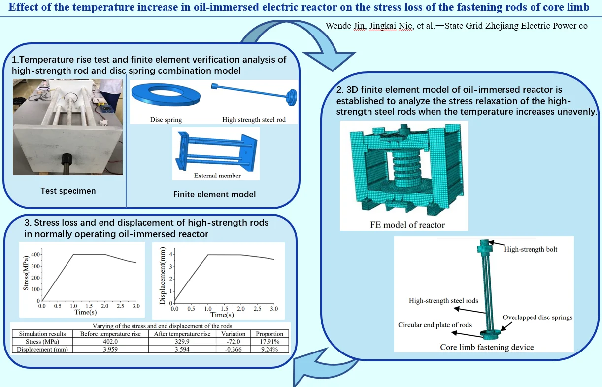
The noise and vibration of large oil-immersed reactor is usually controlled and reduced by using high-strength pretensioned steel rods to fasten iron cores. But the effect of uneven temperature increase in the reactor on the pretension relaxation of steel rods is rarely discussed in previous literatures. A combined fastening device of high-strength steel rod and disc spring is designed to conduct temperature experiment in this paper. And three-dimensional (3D) finite element model is developed to reproduce the experiment process. After the numerical simulation method is verified, finite element analysis of a real BKD-6700/20 oil-immersed reactor is performed. The prestress loss proportion of the high-strength pretensioned steel rods in the oil-immersed reactor under practical operating state is 17.91 % owing to its uneven temperature rise, which can result in significantly weakening of its vibration and noise reduction function.
Highlights
- The noise and vibration of large oil-immersed reactor is usually controlled and reduced by using high-strength pretensioned steel rods to fasten iron cores. Uneven temperature rise will have an effect on the pretension relaxation of steel rods.
- Temperature rise test and finite element verification analysis of high-strength rod and disc spring combination model are carried out. Then three-dimensional finite element model of oil-immersed reactor is established to analyze the stress relaxation of the high-strength steel rods when the temperature increases unevenly.
- It is found that the prestress loss of the rods is 17.91% of design value when oil-immersed reactor is under practical operating state. It reveals the vibration and noise reduction function of core fastening device is significantly weakened.
1. Introduction
A shunt reactor, which compensates for long-distance line capacitance and suppressing the increase of power frequency, is one of the important items of equipment in AC transmission projects [1]. Oil-immersed reactor is mainly composed of core limb, windings, iron yokes, oil-tank, cooling device and protection device. The core limb includes core discs and air gaps (marble or ceramics). And it is fixed between the upper and lower iron yokes with high-strength pretensioned steel rods running through all the laminated core discs, air gaps.
The vibration of core discs and air gaps, caused by electromagnetism and magnetostriction, can be transmitted to the oil tank through both solid and liquid paths, and then the vibration of the oil tank causes the external air vibration to produce noise [2]. When a reactor is connected to an inverter power supply, the noise from the reactor is loud because of the harmonics generated by the inverter [3]. Wu et al. [4] studied the vibration and sound generation and propagation processes of a shunt reactor, and obtained its external noise distribution characteristics. Guo et al. [5] investigated the influence of voltage fluctuations on core vibration of an ultra-high voltage reactor.
For large scale oil-immersed reactor, the core vibration and noise can be reduced by applying enough pretension force in the fastening device of core limb. However, under practical working state, a great deal of magnetic flux leakage causes eddy current loss in side yokes and attachments. Copper loss occurs during the operating of windings. Therefore, local temperatures near windings and core discs arise, leading to the expansion and stress relaxation of the high-strength pretensioned rods. Liu et al. [6] found that local temperature around windings can be as high as 107 ℃ and temperature of the top layer oil can be as high as 86 ℃ after the 500 kV high voltage reactor was put into operation. Liu et al. [7] established the 3D model of BKD200000/1100-145 shunt oil-immersed reactor and its heat dissipation device. The magnetic field distribution and electromagnetic loss of internal structural parts of the reactor was obtained by ANSYS workbench. It was found that local temperature of windings reached 92 ℃, the top oil temperature was 75.5 ℃, while the bottom oil temperature was lower than 40 ℃ after the reactor worked for four hours.
Although the hot-spot location of temperature inside the reactor has been concerned by researchers worldwide [8], the influence of uneven temperature rises on the prestress relaxation of high-strength pretensioned steel rods has rarely been discussed. In this paper, a BKD-6700/20 oil-immersed reactor is adopted as a research case. According to the real structure of the reactor, one end plate of the steel rods is fixed directly on the upper yoke, and the other end plate of the rods is connected to the lower yoke through two overlapped disc springs and high-strength bolt. It is expected that the deformation of the disc spring group matches the expansion or contraction of the rods, in order to keep the prestress of the rods in the effective range. Based on the temperature increase experiment of combined high-strength prestressed rod and disc spring model and the numerical simulation results of the BKD-6700/20 oil-immersed reactor, the stress loss of high-strength pretensioned rods is checked in term of practical operating state of the reactor.
2. Temperature increase test of combined high-strength rod and disc spring model
2.1. Test device and loading patterns
High-strength steel rod and disc spring, provided with the same product category and material as utilized in BKD-6700/20 reactor, are employed hereby. In order to measure the relaxation degree of prestress and elongation of the rod under given preload and temperature change, the test model is designed as shown in Fig. 1. Four sturdy steel columns and two thick steel end plates form a support frame, and one single high-strength steel rod is set in the middle.
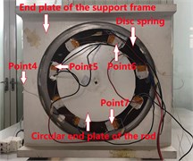
One end of the rod is directly fixed on the end plate with a strong high-strength bolt to limit its displacement, as shown in Fig. 2. The other end of the rod is welded with a circular steel end plate. A single disc spring is arranged against the end plate of the rod and the end plate of the support frame, as shown in Fig. 3. Two end plates are coated with oil to reduce the friction between them and the disc spring, so that the disc spring can slid easily. The rod is applied a 160 kN preload.
The pretensioned rod is heated by surrounding heating tape, and two layers of flame retardant tape are wound outside the heating tape for thermal insulation. Three temperature measuring points (measuring points 1-3) are evenly set on the rod, and one temperature measuring point (measuring point 4) is set at the end plate. The disc spring is evenly provided with 8 heating spots and 3 temperature measuring points (measuring point 5-7), and two layers of foam boards are arranged outside the disc spring for thermal insulation. In order to measure the related temperature increase of the support frame, four temperature measuring points are also mounted on four sturdy steel columns, located at 20 cm away from the circular end plate.
During the test, YQ-128 voltage regulator is used to adjust the temperature, and TP700 multi-channel data recorder is used to record the temperature data. The IL-1000 infrared rangefinder is placed at the movable end of the rod to record its elongation. After the numerical simulation results are calibrated by test data, the prestress loss of the high-strength steel rod can be obtained.
Fig. 1Side view of test device
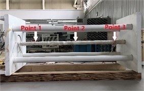
Fig. 2End plate with bolt

Fig. 3End plate with disc spring
According to the temperature values provided in references [6] and [7], the maximum temperature near the windings may be 90 ℃-105 ℃. Therefore, four loading cases are determined: (1) The rod is heated to 90 ℃ and the disc spring is heated to 50 ℃; (2) Temperature of the rod is increased from 90 ℃ to 105 ℃, and the disc spring is maintained at 50 ℃; (3) After the test device is cooled to room temperature, only the rod is heated to 90 ℃; (4) The temperature of the rod is increased from 90 ℃ to 105 ℃, and all other parts of the test device are still at room temperature.
2.2. Test results
Taking loading case 1 as an example, Fig. 4 shows the temperature change curve of each component during the loading process. Table 1 shows the average values of measured temperature of each component and end displacement results of the rod.
Fig. 4Temperature change curve of working condition 1
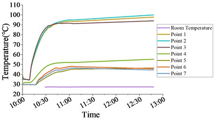
Table 1Records of temperature and end displacement of the rod under all working conditions
Loading case | Temperature of the rod (℃) | Temperature of disc spring (℃) | Temperature of thick steel columns (℃) | Room temperature (℃) | Displacement (mm) |
1 | 93.2 | 48.4 | 32.0 | 27.0 | 0.178 |
2 | 105.5 | 49.3 | 32.6 | 27.0 | 0.240 |
3 | 91.4 | / | / | 29.5 | 0.111 |
4 | 105.4 | / | / | 28.7 | 0.179 |
3. Numerical simulation of the temperature increase test results
3.1. FE model and material property
The experimental device can be divided into three parts: high-strength rod, disc spring and support frame, as shown in Figs. 5 to 7. According to the size of the test model, 3D finite element model is established in ABAQUS with C3D8R element. The rod is set as high-strength steel, with Young’s modulus of 156960 MPa and Poisson’s ratio of 0.3; The support frame is set as Q235B steel, with young's modulus of 210000 MPa and the Poisson’s ratio is 0.274. Young’s modulus of the disc spring is 206000 MPa and its Poisson’s ratio is also 0.3; The linear expansion coefficient of all steels is taken as 1.2×10⁻⁵/℃.
Fig. 5Disc spring
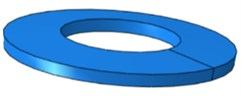
Fig. 6High strength steel rod

Fig. 7External member

The element shape of all components is hexahedral. The mesh size of disc spring, rod and external support frame members is 5, 6 and 10 mm, respectively.
3.2. Contact surface, constraint and loading case
Three contact surfaces are set in this model, which are respectively located between the fixed end bolt and the end plate of the support frame, between the disc spring and the end plate of the support frame, and between the disc spring and the circular end plate of the rod. The friction coefficient of all contact surfaces is 0.3. Constraints are set at the end plate of the frame to restrict the move of the frame, as shown in Fig. 8.
There are two analysis steps. The first step applies preload and the second step applies temperature. In the first step, the temperature load is set as the initial temperature and 160 kN force is loaded onto the rod with bolt load mode; In the second step, the bolt load is changed to keep the bolt length unchanged, and the temperature loads at different parts are applied respectively. Heat conduction effect is considered in the FE model. As shown in Figs. 9 and 10, the rod is divided into two parts: the middle uniform heating part and the end part, which are loaded respectively. As shown in Fig. 11, the four frame columns are divided into two parts: 10 cm and 10-20 cm near the end plate with disc spring, and the temperature load is applied respectively. The temperature changing value of the disc spring is directly applied to the disc spring and the end plate. According to the test results, the initial temperature and temperature values of different parts under four loading cases are shown in Table 2.
Fig. 8Constraints
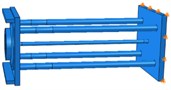
Fig. 9Rod loading area I
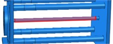
Fig. 10Rod loading area II
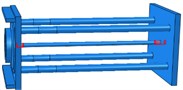
Fig. 11Frame loading area
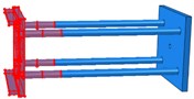
Table 2Temperature load at different parts under various loading cases (℃)
Loading case | Temperature | Circular steel plate | Disc spring | Area I of the rod | Area II of the rod | Area I of columns | Area II of columns |
1 | Initiation | 27 | 27 | 27 | 27 | 27 | 27 |
After heating | 43 | 48 | 93 | 53 | 38 | 32 | |
2 | Initiation | 27 | 27 | 27 | 27 | 27 | 27 |
After heating | 44 | 49 | 106 | 57 | 39 | 33 | |
3 | Initiation | 29 | 29 | 29 | 29 | 29 | 29 |
After heating | 30 | 31 | 91 | 53 | 30 | 30 | |
4 | Initiation | 29 | 29 | 29 | 29 | 29 | 29 |
After heating | 30 | 31 | 106 | 57 | 30 | 30 |
3.3. Simulation results
The simulated and tested displacements of the rod end are compared in Table 3. Overall, the calculated results are larger than tested data. The difference between the simulation result and the experimental value is relatively large for loading cases 1 and 3. There are two reasons for this phenomenon. Firstly, because the whole test device is placed on the table, there is static friction between the test device and the table. The deformation of the support frame is limited, while the influence of friction cannot be considered in the FE model. So tested deformation is slightly larger. Secondly, it takes longer time to complete loading cases 1 and 3 in the laboratory. The heat transmits gradually to the support frame, and the frame also has uneven temperature changes. Whereas data in Table 2 is collected from limited measuring points. It is difficult to accurately reproduce the temperature change of the support frame during FE simulation. When temperature rises from loading cases 1 to 2 and from 3 to 4, the duration is short and the temperature change of the support frame is small. Therefore, the calculated displacement difference between cases 1 and 2 is 0.055 mm, which is close to the test value of 0.062 mm and the error is 11.9 %. When the temperature rises from cases 3 to 4, the calculated displacement difference is 0.060 mm and the tested value is 0.068 mm, with an error of 11.4 %. It shows that the FE analysis method employed in this paper is feasible, and the numerical simulation results can accurately reflect the test results.
The comparison of stress before and after temperature rise of the rod is shown in Table 4. It should be noted that the stress loss proportion in the rod is around 20 % for each loading case.
Table 3Comparison between simulated and tested displacements (mm)
Displacement | Loading case 1 | Loading case 2 | Difference | Loading case 3 | Loading case 4 | Difference |
FE simulation | 0.287 | 0.342 | 0.055 | 0.258 | 0.318 | 0.060 |
Test | 0.178 | 0.240 | 0.062 | 0.111 | 0.179 | 0.068 |
Table 4The stress of pull rod before and after temperature rise
Stress | Loading case 1 | Loading case 2 | Loading case 3 | Loading case 4 |
Prestress (MPa) | 355.3 | 355.3 | 355.3 | 355.3 |
Stress after temperature rise (MPa) | 290.1 | 277.5 | 289.8 | 275.1 |
Stress loss (MPa) | –65.2 | –77.7 | –65.5 | –80.2 |
Proportion | 18.35 % | 21.88 % | 18.42 % | 22.57 % |
4. Stress loss of high-strength rods in normally operating oil-immersed reactor
4.1. FE model of the reactor
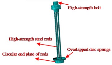
The 3D FE model of the BKD-6700/20 reactor is shown in Fig. 12. C3D8R element is still used, with a total of 60196 elements. The core limb fastening device is composed of three high-strength pretensioned rods, high-strength bolt, circular thick steel end plates and two overlapped disc springs, as shown in Fig. 13.
The material property parameters of high-strength rod, disc spring and iron yokes are all the same as those given in Section 2.1. The silicon steel sheet of the core is B30P105 and its density is 7650 kg/m3. The air gap cushion block is marble with a density of 2730 kg/m3. Tie constraints are adopted between iron yoke and bottom square hollow section. 3D hinged constraints are set on the bottom square hollow section. Contact surfaces are arranged between each core disc and air gap block, core discs and both the upper and lower cover plates, each disc spring and the steel plates its contacts. The normal direction of every contact surface uses hard contact mode, allowing separation after contact; Penalty friction is adopted in tangential direction. Because the reactor is immersed in oil, the friction coefficient of the contact surface between iron core cake and marble is set to 0.2, and the friction coefficient of other contact surfaces is set to 0.1.
Fig. 12FE model of reactor
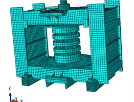
Fig. 13Core limb fastening device
4.2. Loading pattern
There are three analysis steps in total. In the first step, 520 kN preload is applied to the high-strength rod in the form of bolt load; In the second step, the rod preload is kept and gravity load is implemented; In the third step, the temperature increase is provided. The bolt load is turned to constant current length mode and the gravity load is still on. The disc spring is heated from 20 ℃ to 50 ℃ and the high-strength pull rod is heated from 20 ℃ to 90 ℃.
4.3. Simulation results
The end displacement and stress changes of high-strength pretensioned rod are shown in Figs. 14 and 15 respectively. The effect of temperature change on the prestress and end displacement in the rod is listed in Table 5. It is shown that the prestress loss proportion of the rods reaches 17.91 % when oil-immersed reactor is normally operating, due to the uneven temperature change in the oil tank. Therefore, the fastening effectiveness of the core limb is greatly reduced. It means that the vibration and noise reduction function of the fastening device is significantly weakened.
In Table 5, the positive displacement corresponds to the positive direction of axis in Fig. 12. The displacement change of –0.366 mm represents that the end of the pull rod moves 0.366 mm to the negative direction of axis after the temperature increases. It is still in the deformation range of the disc spring.
Fig. 14Stress of the rods
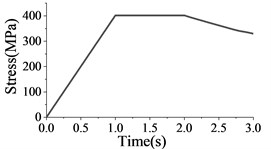
Fig. 15End displacement of the rods
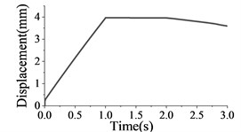
Table 5Varying of the stress and end displacement of the rods
Simulation results | Before temperature rise | After temperature rise | Variation | Proportion |
Stress (MPa) | 402.0 | 329.9 | –72.0 | 17.91 % |
Displacement (mm) | 3.959 | 3.594 | –0.366 | 9.24 % |
5. Conclusions
This paper focus on the influence of the temperature increase in oil-immersed electric reactor on the stress loss of the fastening high-strength steel rods of core limb. A simplified model for core limb fastening device of BKD-6700/20 oil-immersed shunt reactor is designed to conduct temperature experiment. Based on the heating test results of the simplified model, numerical simulation method realized by ABAQUS software is validated. Subsequently, 3D finite element model of the BKD-6700/20 oil-immersed reactor is established to analyze the stress relaxation of the high-strength steel rods when the temperature increases unevenly. It is found that the prestress loss of the rods is 17.91 % of design value when oil-immersed reactor is under practical operating state. It reveals the vibration and noise reduction function of core fastening device is significantly weakened.
The research findings in the paper can provide constructive guidance for the scientific optimization of the core fastening device design for reactors. Further research should be carried out to control the fluctuating of rod stress within required range.
References
-
F. Lü, J. Guo, L. Niu, J. Geng, and Y. Pan, “A new 3D method for reactor core vibration based on silicon steel lamination rules and application in UHV shunt reactors,” Mathematical Problems in Engineering, Vol. 2019, pp. 1–11, Oct. 2019, https://doi.org/10.1155/2019/7290536
-
F. Zhang, S. Ji, Y. Shi, C. Zhan, and L. Zhu, “Investigation on vibration source and transmission characteristics in power transformers,” Applied Acoustics, Vol. 151, No. 8, pp. 99–112, Aug. 2019, https://doi.org/10.1016/j.apacoust.2019.03.011
-
Y. Gao, M. Nagata, K. Muramatsu, K. Fujiwara, Y. Ishihara, and S. Fukuchi, “Noise reduction of a three-phase reactor by optimization of gaps between cores considering electromagnetism and magnetostriction,” IEEE Transactions on Magnetics, Vol. 47, No. 10, pp. 2772–2775, Oct. 2011, https://doi.org/10.1109/tmag.2011.2154378
-
S. Y. Wu et al., “Simulation analysis and experimental research on vibration and noise of UHV shunt reactor based on multi physical field coupling,” (in Chinese), Electric Power Automation Equipment, Vol. 40, No. 3, pp. 122–127, 2020, https://doi.org/10.16081/j.epae.202002007
-
J. Guo, J. Geng, and F. Lü, “Influence of voltage fluctuations on core vibration of a UHV shunt reactor,” International Journal of Applied Electromagnetics and Mechanics, Vol. 66, No. 4, pp. 561–580, Aug. 2021, https://doi.org/10.3233/jae-201564
-
Z. W. Liu, B. K. Zhu, and S. Y. Yang, “Cause analysis and treatment of high oil temperature in 500 kV high voltage reactor,” (in Chinese), Transformers, Vol. 46, No. 11, pp. 65–66, 2009.
-
F. X. Liu et al., “Numerical and experimental research of internal temperature field of oil-immersed core shunt reactor with ultra-high voltage,” (in Chinese), High Voltage Apparatus, Vol. 53, No. 1, pp. 163–168, 2017, https://doi.org/10.13296/j.1001-1609.hva.2017.01.027
-
S. Xiao et al., “Study on loss and temperature increases in hollow oil-immersed reactors,” in IOP Conference Series: Materials Science and Engineering, Vol. 486, No. 1, p. 012025, Jun. 2019, https://doi.org/10.1088/1757-899x/486/1/012025
About this article

The work was supported by Science and Technology Project of the State Grid Corporation of China Headquarters: In-Depth Research and Application of the Key Technology of Noise Reduction for Single-Column UHV Shunt Reactors (5200-201919104A-0-0-00).
