Abstract
The paper is aimed at studying the motion conditions of the vibratory compacting machine equipped with the crank excitation mechanism characterized by the changeable geometrical parameters. Unlike numerous scientific publications devoted to similar subject, the novelty of the present research consists in the improved design of the vibro-impact plate compactor and the developed mathematical model describing the motion conditions of the compactor’s oscillatory system. It is proposed to use the crank mechanism to excite the oscillations of the impact body acting upon the frame of the compacting plate at a certain angle to the surface being compacted. The main idea of this improvement is to provide the self-propelling locomotion conditions of the compactor and to reduce the pushing force that must be applied by the operator. The research results obtained by means of the numerical modeling in Mathematica software describe the dynamic behavior of the compactor’s oscillatory system under different geometrical parameters of the crank excitation mechanism (crank eccentricity, impact gap, etc.). The material of the paper can be of significant practical interest for the designers and engineers dealing with the development of new vibratory compactors and the improvement of compacting technologies.
Highlights
- The idea of implementing the vibro-impact crank-type excitation mechanism for providing the self-propelling locomotion conditions of the vibratory plate compactor is proposed.
- The improved design of the vibratory plate compactor is developed; the corresponding three-mass oscillatory system is considered; the differential equations describing the system motion are derived.
- The numerical modeling allowed for obtaining the time dependencies of the compactor horizontal displacement and velocity, and the normal force exerted by the compactor on the surface being compacted.
- Based on the numerical modelling results the conclusion about reducing the extra pushing force that must be applied by the operator for setting the compactor into motion is drawn.
1. Introduction
Numerous engineers and researchers are currently working on the development of the energy-efficient and high-performance vibratory compacting equipment. The problems of ensuring the controllable operational conditions of the compactors in accordance with the changeable technological requirements are of significant interest. Among the great variety of problems arising while designing and implementing the vibratory compacting machines, the problems of providing the self-propelling locomotion conditions and reducing the extra pushing force that must be applied by the operator are of the most important ones.
The “vibratory tamper – asphalt mixture” interaction during the compaction process is thoroughly investigated in [1]. The technique of design optimization of the self-propelled plate compactor equipped by the eccentric (inertial) vibration exciter is considered in [2]. The paper [3] is devoted to modeling the operation of the three-mass stacker vibration plate and testing the compaction quality. In [4], the authors developed a nonlinear dynamic model describing the “asphalt mixture – vibratory screed” interaction and studied the efficiency of the compaction process. The papers [5] and [6] consider the improved designs of the crank-type vibro-impact mechanisms that can be used in various compacting equipment and present the results of the investigations of the mechanisms dynamic behavior under different operational conditions. The dynamics of the self-propelled vibro-impact locomotion system moving along the horizontal surface characterized by various dry and isotropic friction levels is studied in [7]. The paper [8] considers the vibro-impact capsule system subjected to bidirectional drifts. Similar systems with one-sided and two-sided impact constraints are studied in [9].
The carried out analysis of the scientific publications dedicated to vibratory compacting machines [1]-[6] and self-propelled vibro-impact locomotion systems [7]-[9] has shown that the problems of the simultaneous implementation of the vibro-impact operational conditions and the self-propelling drives in the improved designs of the plate compactors are not thoroughly investigated. Therefore, the previous publications of the authors substantiated the optimal inertia-stiffness parameters of the three-mass vibratory system excited by the crank mechanism [10], considered the improved design of the crank excitation mechanism with controllable geometrical parameters [11], and studied the dynamic behavior of the three-mass vibro-impact system able to slide along a rough horizontal surface [12]. The novelty of the present paper consists in implementing the vibro-impact crank-type excitation mechanism for providing the self-propelling locomotion conditions of the vibratory plate compactor and reducing the extra pushing force that must be applied by the operator for setting the compactor into motion.
2. Research methodology
2.1. General design and dynamic diagram of the vibro-impact plate compactor
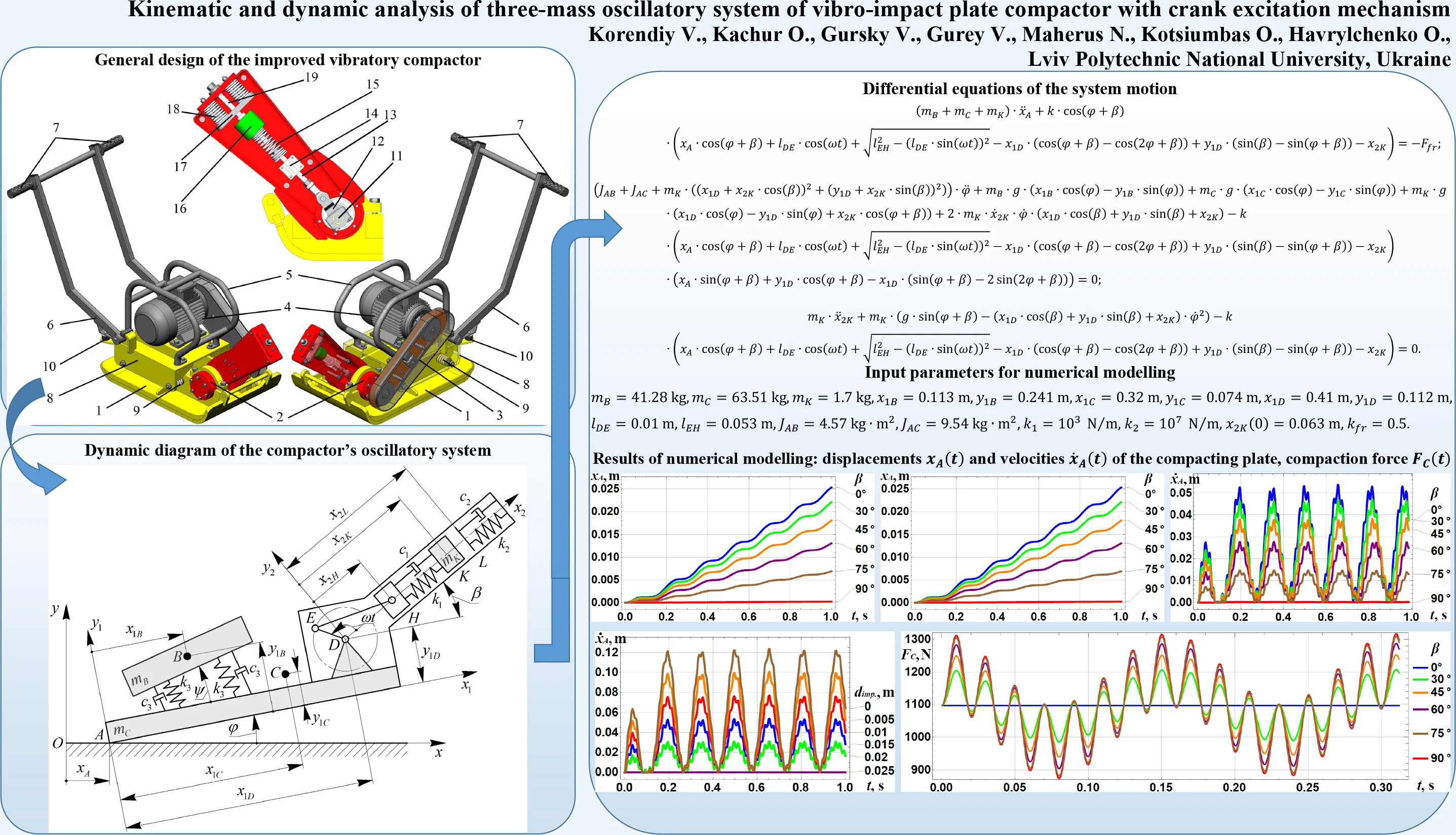
The improved design of the vibro-impact plate compactor is presented in Fig. 1. The compacting plate 1 acting upon the surface to be compacted is set into the oscillatory motion by means of the vibration exciter 2. The belt drive 3 is used for transmitting the torque from the shaft of the electric motor 4 to the crankshaft of the vibration exciter 2. The handles 5 are designed for carrying the compactor, while the levers 6 and the handles 7 are used by the operator for pushing it or changing its motion direction. The motor 4, the handles 5, 7, and the levers 6 are mounted on the upper sprung platform 8 being suspended by the vibration absorbers 9 from the lower platform (compacting plate) 1. The absorbers 9 and the rubber dampers 10 are used to reduce the influence of vibrations on the operator. Unlike most existent vibratory compactors, the improved machine is equipped with the crank-type vibro-impact excitation mechanism 2. The latter consists of the crankshaft 11, connecting rod 12, sliding bar 13, guide (pilot) bearing 14, coil spring 15, impact body 16, impact plate 17, shock springs 18, and guide axis 19.
Fig. 1General design of the improved vibratory compactor
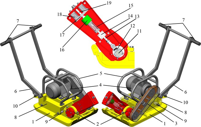
The operation of the crank-type vibro-impact excitation mechanism 2 can be explained as follows. The rotation of the crankshaft 11 sets the connecting rod 12 into the plane-parallel motion. The latter excites the linear oscillations of the sliding bar 13 supported by the guide (pilot) bearing 14. The spring 15 connects the bar 13 to the impact body 16 sliding along the guide axis 19. While oscillating, the body 16 impacts the plate 17 causing the transmission of its kinetic energy to the platform 1 and setting it into the oscillatory motion. The shock springs 16 are of the large stiffness and are used to prevent the damage of the exciter’s frame during the impacts.
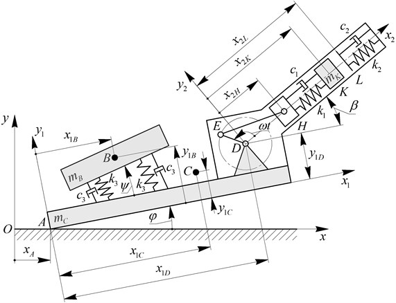
The dynamic diagram of the compactor’s three-mass oscillatory system is presented in Fig. 2. The inertial frame of reference is adopted to study the plane motion of the compacting plate. The other two reference systems and are used to describe the relative motions of the sprung platform and the impact body with respect to the compacting plate, respectively. The considered oscillatory system is characterized by six degrees of freedom that correspond to the following generalized coordinates: – horizontal displacement of the compacting plate; – angular displacement of the compacting plate with respect to the surface being compacted; , , – linear and angular displacements of the sprung body (upper platform) with respect to the compacting plate; – linear displacement of the impact mass with respect to the compacting plate. One degree of freedom characterizing the rotation of the crank is considered to be controllable, i.e., the crank rotates at a constant angular velocity . The vibration isolators supporting the upper platform are modeled by the springs of the stiffness and the absorbers with the damping (viscous friction) coefficients . The springs connecting the slider to the impact body and the impact plate to the lower platform’s frame are characterized by the stiffness coefficients , and the damping coefficients , , respectively.
Fig. 2Dynamic diagram of the compactor’s oscillatory system
2.2. Mathematical model of the compactor’s oscillatory system motion
In the present paper, let us consider the plane oscillatory motion of the compacting plate excited by the vibro-impact crank mechanism. In such a case, the relative motion of the sprung platform with respect to the compacted plate is to be neglected, i.e., , and , remain constant. In addition, let us neglect the energy dissipation in the spring elements: 0. These assumptions allow for simplifying the mathematical model of the compactor’s oscillatory system motion, and deriving only three differential equations describing the linear and angular motion of the compacting plate, and the linear oscillations of the impact body:
where , , are the masses of the upper platform, the compacting plate and the impact body, respectively; is the angle between the axes and ; , are the lengths of the crank and the connecting rod of the excitation mechanism, respectively; , , , , , are the coordinates describing the positions of the mass centers of the upper platform and the compacting plate, and of the point in the reference system , respectively; , – the moments of inertia of the compacting plate and the upper platform turning about the point ; is the free fall acceleration; is the function describing the change of the stiffness coefficient during the impact; is the friction force acting upon the compacting plate during its sliding.
The stiffness function is defined as follows:
where is the initial distance between the point and the impact plate .
The dry friction force that acts upon a vibro-impact system sliding along a rough surface can be modeled by the simplified expressions derived in numerous publications, e.g., [7]-[9], [12].
3. Results of numerical modeling
The 3D model of the vibratory plate compactor (Fig. 1) designed in SolidWorks software allows for defining the basic geometrical and inertial parameters of the considered oscillatory system: 41.28 kg, 63.51 kg, 1.7 kg, 0.113 m, 0.241 m, 0.32 m, 0.074 m, 0.41 m, 0.112 m, 0.01 m, 0.053 m, 4.57 kg∙m2, 9.54 kg∙m2, 103 N/m, 107 N/m. The distance influencing the impact gap and the angle defining the inclination of the vibro-impact mechanism relative to the compacting plate are the changeable parameters effecting the kinematic and dynamic characteristics of the compactor. While carrying out further numerical modeling in Mathematica software, the following value of the impact gap will be used: , where 0.063 m is the initial position of the impact mass. The dry friction coefficient that appears in the expression of the friction force is following: 0.5.
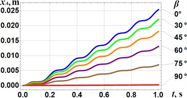
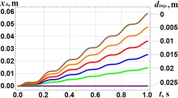
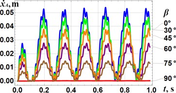
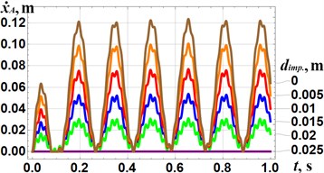
The results of numerical modeling of the compactor motion at different design parameters have been obtained in Mathematica software and are presented in Fig. 3. The reduction of the inclination angle of the vibro-impact mechanism relative to the compacting plate from 90° to 0° at 0.015 m causes the increase in the average horizontal speed of the plate from 0 m/s to 0.026 m/s. In this case, the maximal value of the plate speed reaches 0.052 m/s at 0°. The increase in the impact gap from to causes the reduction of the plate average speed from 0.059 m/s to 0 m/s. In this case, the maximal value of the plate speed reaches 0.124 m/s at 0°. Therefore, in order to improve the self-propelling properties of the vibro-impact compactor, it is necessary to place the crank excitation mechanism in parallel to the compacting plate and to provide the lowest possible value of the impact gap taking into account the strength conditions of the corresponding impacting elements.
Fig. 3Results of numerical modelling of the kinematic characteristics (displacements xAt and velocities x˙At) of the compacting plate at different design parameters: a), c) β= 0°, 30°, 45°, 60°, 75°, 90° and dimp.= 0.015 m; b), d) β= 0° and dimp.= 0, 0.005 m, 0.01 m, 0.015 m, 0.02 m, 0.025 m
a)
b)
c)
d)
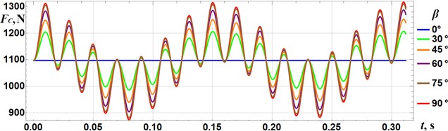
Fig. 4 presents the time dependence of the normal force exerted by the compacting plate on the surface being compacted. In this case, the change of the inclination angle of the vibro-impact mechanism relative to the compacting plate has been taken into account. The smallest amplitude value of the compacting force 1094 N takes place at 0°, whilst the largest value 1315 N – at 90°. Therefore, the non-detachable compaction conditions (i.e., 0°) are implemented.
Fig. 4Time dependence of the normal force exerted by the compactor on the surface being compacted
4. Conclusions
The paper presents the results of the investigations on the kinematic and dynamic characteristics of the three-mass oscillatory system of the vibro-impact plate compactor with crank excitation mechanism. Based on the carried-out analysis of the information sources on the subject of the paper, the conclusion about the necessity of implementing the vibro-impact crank-type excitation mechanism for providing the self-propelling locomotion conditions of the vibratory plate compactor is drawn. This idea allows for reducing the extra pushing force that must be applied by the operator for setting the compactor into motion. Therefore, the improved design of the vibro-impact plate compactor is proposed (see Fig. 1), and the corresponding dynamic diagram of its oscillatory system is developed (see Fig. 2). The simplified mathematical model describing the motion of the compacting plate and the impact body is derived (see Eq. (1-4)). The 3D model of the vibratory plate compactor designed in SolidWorks software and the numerical modeling of the oscillatory system motion carried out in Mathematica software allowed for obtaining the time dependencies of the compactor horizontal displacement and velocity (see Fig. 3), and the normal force exerted by the compacting plate on the surface being compacted (see Fig. 4).
References
-
V. Nguyen, R. Jiao, and J. Zhang, “Analyzing the compacting energy and force distribution during the tamper-asphalt mixture interaction,” Journal of Vibroengineering, Vol. 23, No. 5, pp. 1148–1159, Aug. 2021, https://doi.org/10.21595/jve.2021.21937
-
R. Morariu-Gligor, A. Crișan, and F. Șerdean, “Optimal design of an one-way plate compactor,” Acta Technica Napocensis – Series: Applied Mathematics, Mechanics, and Engineering, Vol. 60, No. 4, pp. 557–564, Dec. 2017.
-
R. T. Emelyanov, A. P. Prokopev, E. S. Turysheva, I. I. Terekhova, and N. A. Tkachenko, “Modeling of dynamic system “vibratory plate – soil” as an object quality control of compaction,” in Journal of Physics: Conference Series, Vol. 1399, No. 4, p. 044097, Dec. 2019, https://doi.org/10.1088/1742-6596/1399/4/044097
-
Y. Shi, H. Liu, and G. Wang, “Modeling of asphalt mixture-screed interaction: A nonlinear dynamic vibration model for improving paving density,” Construction and Building Materials, Vol. 311, p. 125296, Dec. 2021, https://doi.org/10.1016/j.conbuildmat.2021.125296
-
S. V. Metrikin, A. L. Igumnov, and V. I. Nikiforova, “The dynamics of eccentric vibration mechanism (Part 1),” Journal of Vibroengineering, Vol. 19, No. 7, pp. 4854–4865, Nov. 2017, https://doi.org/10.21595/jve.2017.18346
-
A. L. Igumnov, S. V. Metrikin, V. I. Nikiforova, and L. N. Fevral’skikh, “The dynamics of eccentric vibration mechanism (Part 2),” Advanced Structured Materials, Vol. 137, pp. 173–190, 2021, https://doi.org/10.1007/978-3-030-53755-5_12
-
K.-T. Nguyen, N.-T. La, K.-T. Ho, Q.-H. Ngo, N.-H. Chu, and V.-D. Nguyen, “The effect of friction on the vibro-impact locomotion system: modeling and dynamic response,” Meccanica, Vol. 56, No. 8, pp. 2121–2137, Aug. 2021, https://doi.org/10.1007/s11012-021-01348-w
-
B. Guo, J. Páez Chávez, Y. Liu, and C. Liu, “Discontinuity-induced bifurcations in a piecewise-smooth capsule system with bidirectional drifts,” Communications in Nonlinear Science and Numerical Simulation, Vol. 102, p. 105909, Nov. 2021, https://doi.org/10.1016/j.cnsns.2021.105909
-
Y. Yan, Y. Liu, and M. Liao, “A comparative study of the vibro-impact capsule systems with one-sided and two-sided constraints,” Nonlinear Dynamics, Vol. 89, No. 2, pp. 1063–1087, Jul. 2017, https://doi.org/10.1007/s11071-017-3500-7
-
V. Korendiy, O. Lanets, O. Kachur, P. Dmyterko, and R. Kachmar, “Determination of inertia-stiffness parameters and motion modelling of three-mass vibratory system with crank excitation mechanism,” Vibroengineering Procedia, Vol. 36, pp. 7–12, Mar. 2021, https://doi.org/10.21595/vp.2021.21924
-
O. Lanets, O. Kachur, V. Korendiy, and V. Lozynskyy, “Controllable crank mechanism for exciting oscillations of vibratory equipment,” in Lecture Notes in Mechanical Engineering, Cham: Springer International Publishing, 2021, pp. 43–52, https://doi.org/10.1007/978-3-030-77823-1_5
-
V. Korendiy, V. Gursky, O. Kachur, V. Gurey, O. Havrylchenko, and O. Kotsiumbas, “Mathematical modeling of forced oscillations of semidefinite vibro-impact system sliding along rough horizontal surface,” Vibroengineering Procedia, Vol. 39, pp. 164–169, Dec. 2021, https://doi.org/10.21595/vp.2021.22298
Cited by
About this article

