Abstract
A parametric study has been conducted on the characterization of machined surfaces of some commercially available polymeric materials structures obtained under surface finishing. More specifically, the major mechanical properties of the machined surface, namely, surface roughness, hardness, temperature, as well as chips deformation are evaluated under different machining conditions, and are analyzed in a comparative fashion for a number of commercial polymeric material samples that include Acrylic (Perspex), High Density Polyethylene (HDPE) and Unplasticized Polyvinyl Chloride (uPVC). The machining of the samples is realized through a standard horizontal shaper machine with HSS single point V-shaped cutting tool at different cutting speed and depth of cut. The measured results show that the surface properties of the polymeric materials are affected quite significantly by the change of machining parameters. Microstructures of the chips reveal that crack-like flaws are formed at higher cutting speeds and lower depths of cut.
Highlights
- The machined surfaces of Acrylic samples show better surface finish among the three polymeric materials, Acrylic (Perspex), High Density Polyethylene (HDPE) and Unplasticized Polyvinyl Chloride (uPVC).
- Chips deformation is found to increase with cutting speed and depth of cut, although the role of cutting speed is identified to be more effective than depth of cut.
- Microstructures of the chips reveal that fewer cracks are observed at higher cutting speeds and lower depths of cut.
1. Introduction
Polymers are basically organic materials having long chain carbon molecules. Polymer molecules are formed by a number of monomers. Generally, plastics and plastic composite materials are used in production of plastic components. These plastic materials are now enjoying wide spread applications for specialty purposes where the properties like, toughness, rigidity, abrasion resistance and heat resistance are important [1, 2]. The common engineering applications of plastic materials are thus gears, cams, bearings, bushes, valve seats, etc. On the other hand, plastic materials have few limitations over conventional metallic applications. For example, thermal tolerances of plastic materials are comparatively low, as a result, applications of plastics in high working temperature are not favorable. Thermal expansion of plastics is approximately ten times higher than that of metals, which is thus one of the constraints needs to be consider in their application. Plastic deformation occurs in some plastic materials under heavy stresses [3-6].
Most of the plastic products require some degree of machining and finishing after their processing and before putting in the marketplace. The term machinability generally refers to the ease with which a material can be cut/machined permitting the removal of the material with a satisfactory surface finish at a low cost. Moreover, materials with good machinability require little power to machine with less machining time, easily obtain a good surface finish, and do not cause much wear to the tool material; such materials are said to be free machining. It can be noted that the factors that typically improve a material’s performance often degrade its machinability. As far as economical manufacturing is concerned, engineers are always challenged to find suitable ways to improve machinability without harming the performance.
Quantitative prediction of machinability is basically a difficult proposition, which is because of the fact that machining has a large number of variables and is influenced by the internal nature of the material, thereby showing different kinds of behavior by different types of material under the same machining conditions. Not only that, even among the same class of materials (metals and alloys, for example) subtle variations in microstructure are found to give rise to different characteristics under the same operating conditions. The prediction of surface roughness for metals in terms of cutting speed, feed rate and depth of cut has been reported in the literature [7-11]. The corresponding results revealed that the machining variables like, feed rate and depth of cut have a negative influence on the surface roughness. However, it has been also reported that there is an optimum value of cutting speed that provides a minimum level of surface roughness [7]. Further, in case of machining of high-strength steels, the effect of feed rate is found to be much more pronounced on the surface roughness compared to those of cutting speed and depth of cut [8]. For machinable glass-ceramics, an increase in cutting speed decreases surface roughness, while the same is increased with an increase in either the feed rate or the depth of cut, although feed rate has the most dominant effect on the surface roughness [9]. In case of machining mild steels, the feed rate was the main influencing factor for surface roughness, which was found to increase with increasing feed rate. Among other parameters, depth of cut was found to be less sensitive to surface roughness than the cutting speed [10]. For turning of titanium alloy, surface roughness increases with the increase of cutting speed and feed rate, and decreases with the decrease in depth of cut [11]. In general, the use of higher cutting speed with lower feed rate produces a better surface finish, which is mainly due to the increase in temperature [12, 13]. In addition, an investigation was carried out that analyzed the effects of radial rake angle of the tool in combination with cutting speed and feed rate on the surface roughness [14]. Nowadays plastics are being widely employed in the industrial sector. The use of plastics with superior characteristics has been increased in several areas, such as equipments of precision, electronics and optics. Because of the need of high dimensional accuracy and good surface finish, plastic components for these ends should be produced by means of machining processes instead of conventional molding processes [15, 16].
In the present paper, an attempt is made to characterize machined surfaces of three commercially available polymeric materials structures, namely, acrylic, HDPE and uPVC in terms of some major mechanical properties of interest, which include surface roughness, hardness, temperature, as well as chips deformation. The measured results are then analyzed in the perspective of major machining parameters and are demonstrated in a comparative fashion to explore the machinability of the above polymeric materials in a quantitative fashion.
2. Experimental procedure
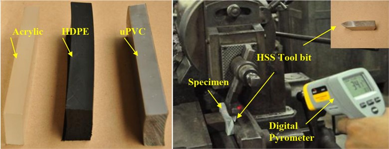
Machining operation was carried out with the help of a horizontal push cut type shaper machine on commercially available Acrylic (Perspex), High Density Polyethylene (HDPE) and Unplasticized polyvinyl chloride (uPVC) samples of dimension 15 mm × 75 mm × 150 mm. The HSS single point V-shaped cutting tool with an angle of 60°, clearance angle of 8° and 0.8 mm notch radius was used. For machining, the depth of cut considered was 0.5, 1.0, 2.0 and 4.0 mm and stroke per minute was 11, 48, 70 and 99 to maintain the cutting speed 3.0, 13.1, 19.4 and 27.5 m/min, respectively. The feed rate and stroke length was kept constant throughout the experiment at 0.254 mm/stroke and 165.0 mm, respectively. After each cut average surface roughness (Center Line Average Roughness, ) and hardness of the machined surface was measured. Attempt was also made to measure the surface temperature of the sample with the help of digital pyrometer during machining. Surface roughness of machined surfaces was measured with a surface roughness-measuring instrument (Talysurf). Each data of surface roughness presented was calculated as the average of ten readings taken. In order to study the effect of work hardening, the hardness of the machined surface was measured by Durometer Hardness tester. A minimum of fifteen hardness measurements was performed on each sample, and the average of these readings has been taken as the corresponding representative hardness. The machined chips for all three materials were photographed using DSLR camera in as-received condition. The optical microscopy of all these chip samples was carried out following the standard procedure. The micrographs of the different machined surfaces were taken with a USB microscope. The photograph of the experimental set-up is shown in Fig. 1.
Fig. 1Photograph of the machining setup for shaping the surface
For determination of chip deformation, the inclined depth of cut was first determined as shown in Fig. 2, where:
Fig. 2Inclined depth of cut
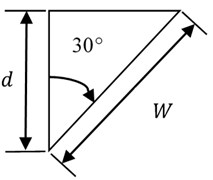
From Eq. (2) for different depth of cut the lateral depth of cut was found and then the chip width () was compared to find the percentage of deformation. A vernier caliper was used to determine .
Deformation along the direction of sample width %:
Table 1Tool geometry and machining condition
Tool nose radius (mm) | 0.8 |
Back rake angle (°) | 5 |
Clearance angle (°) | 8 |
Feed rate (mm/stroke) | 0.254 |
Depth of cut (mm) | 0.5, 1.0, 2.0, 4.0 |
Cutting speed (m/min) | 3.0, 13.1, 19.6, 27.6 |
3. Results and discussions
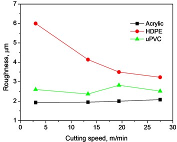
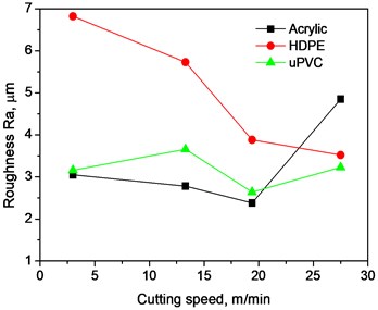
Fig. 3 shows the variation of surface roughness with cutting speed at different depths of cut for the polymer materials. From the figures, it is evident that HDPE samples has the highest average surface roughness followed by those of uPVC and Perspex. The change in surface roughness with the increase in cutting speed is found to be most significant for HDPE. In general, for all depths of cut, increase in cutting speed causes better surface finish. It is observed for HDPE samples that, for higher depth of cut, the decrease in surface roughness with increased cutting speed is more significant than that at lower depth of cut. The advantage of improving surface quality by increasing the cutting speed seemingly attenuates at a very high cutting speed, which is found to be more pronounced, especially for higher depths of cut. For Perspex and uPVC samples, the change in roughness with the increase in cutting speed is less prominent compared to that of HDPE. For example, at 2 mm depth of cut, Perspex shows almost no change in surface roughness with respect to cutting speed. Similar trend is observed for uPVC at lower depth of cut. The best surface finish for Perspex samples is obtained at 2 mm depth of cut with the cutting speed 3 m/min. Again, uPVC shows the best surface finish at the same depth of cut but with a cutting speed of 13.1 m/min. On the other hand, the optimal surface condition for HDPE samples is obtained at 1 mm depth of cut and 27.5 m/min cutting speed.
The influential effect of cutting speed in minimizing the surface roughness of polymeric materials is realized to be quite significant. This is due to the fact that, at low cutting speeds less heat is generated, and due to the poor thermal conductivity of the polymeric sample, this heat is mostly carried away by the tool resulting in less softening of the work material. High cutting speed is associated with the higher cutting temperature at the tool-work piece interface, which causes increasing softening of the work piece material and reduction of cutting forces, and hence leading to better surface finish [17]. It is evident from Fig. 1 that surface roughness increases with the increase of depth of cut, which is mainly due to increase in thermal load and vibration on the machine tool. Furthermore, because of more contact area between the tool and work piece, higher friction and tool wear take place, thereby leading to higher surface roughness [18]. The chip-tool interface temperature is closely associated with the cutting speed. With the increase of cutting speed, frictional resistance increases, which, in turn, induces higher temperature in the cutting zone. With the increase in depth of cut, dimension of the resulting chip is increased, which eventually increases the friction and thus temperature. When the depth of cut is increased, the chip section and friction of chip-tool is increased, which leads to an increase in temperature [19].
The characteristic of assuming higher average surface roughness of HDPE can be explained by the fact that it has very densely packed linear chains with almost zero side branching, which eventually allows the chains to move relative to each other. As a result, when HDPE samples are subjected to machining, large plastic zone is developed at the tool-material interface, resulting in considerable plastic deformation in a large affected volume before material is removed, thereby increasing surface roughness. It is known that uPVC chains are atactic, which cause increased space and decreased cohesion among them. Therefore, less shear stress and thus a smaller plastic deformation region is noticed, which results in relatively less surface roughness. It is known that acrylic is fully amorphous with chains spaced far apart, resulting in least cohesion among them. Therefore, it breaks away long before high shear forces can deform the material, i.e., plastic deformation region is much smaller compared to the other two specimens, which eventually results in decreasing roughness [20]. The higher values of roughness of HDPE samples compared to the other two material samples in Fig. 1 can also be attributed to the differences in their chain arrangements, the layered arrangement of HDPE chains make it much more ductile; while uPVC is less ductile with acrylic being completely brittle. As samples of HDPE is fully ductile, it tends to deform plastically at low cutting speeds due to lower shear forces and larger shear area, which leads to higher surface roughness. uPVC and acrylic are, due to their brittle-like behaviour, easier to machine with less shear forces, thereby resulting in good surface finish even at lower cutting speeds [21, 22]. Moreover, the specific heat of HDPE is much higher with a lower coefficient of friction, resulting in generation of lower temperature at the surface layer of the material, and thus less thermal softening at lower temperatures, which eventually causes worse surface finish. On the other hand, the specific heat is much lower for the other two materials while their coefficient of friction is much higher, which results in higher temperature generation and significant thermal softening even at lower cutting speeds, and thus better surface finish.
Fig. 3Variation of surface roughness with cutting speed at different depths of cut
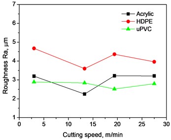
a) 0.5 mm
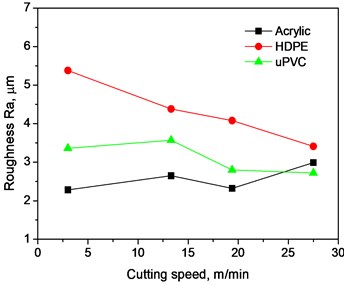
b) 1.0 mm
c) 2.0 mm
d) 4.0 mm
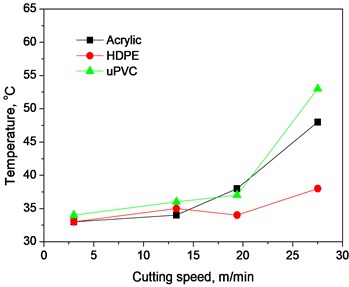
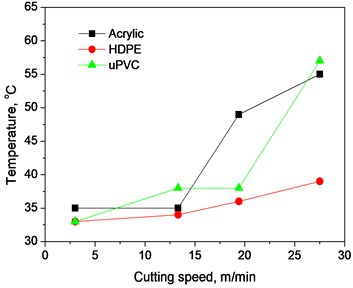
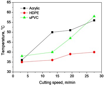
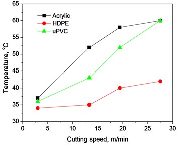
The increasing characteristics of temperature at the work surface as a function of cutting speed for the selected depths of cut are described in Fig. 4. For all four cases, temperature increases with the increase of cutting speed as well as depth of cut, but the influence of cutting speed is observed to be more prominent for all the samples. Least rise in temperature is identified for HDPE samples for all depths of cut, while interesting phenomenon is observed for uPVC and acrylic samples. At the lowest depth of cut, uPVC shows higher rise in average temperature compared to that of acrylic; while at higher depths of cut, acrylic shows on average a greater temperature rise. It is also evident that, in most cases, uPVC exhibits gradual increase in temperature with lower cutting speeds, and then suddenly experiences an exponential-like increase. The temperature of acrylic samples tends to rise sharply at lower cutting speeds, and then slowly steadies out at higher cutting speeds. With increasing depth of cut the average surface temperature of the polymers also tends to increase. These characteristics can be explained by their thermal and physical properties, which are also influenced by their structural nature [23]. HDPE has the least density and coefficient of friction while having the highest thermal conductivity, but it also has the highest specific heat due to increased intermolecular (inter-chain) attraction, which results in less temperature rise as the amount of heat generated at the tool-work interface is quite less compared to the other samples for all depths of cut. Although uPVC has lower specific heat capacity and coefficient of friction compared to acrylic, acrylic has thermal conductivity higher than uPVC resulting in higher rise in temperature for uPVC at the lowest depth of cut. With the increase in depth of cut, volume affected by shear force increases for both uPVC and acrylic; and for the same affected volume, acrylic will show less temperature rise as it has less density compared to uPVC. Further, among the present materials, acrylic has marginally higher thermal conductivity together with highest coefficient of friction, which leads to more heat generation at the tool-specimen interface and more heat being carried to the affected volume offsetting the effect of uPVC having a lower specific heat capacity and leading to grater increase in temperature for acrylic. Because of higher frictional coefficient, acrylic also explains the reason of assuming a higher temperature sensitive response to increasing cutting speeds. Increasing depth of cut results in more shear forces accompanied by higher plastic deformation, which, in turn, leads acrylic to dissipate more frictional work as it has a higher frictional coefficient.
Fig. 4Variation of surface temperature with cutting speed at different depth of cut
a) 0.5 mm
b) 1.0 mm
c) 2.0 mm
d) 4.0 mm
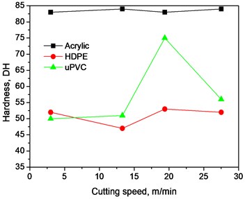
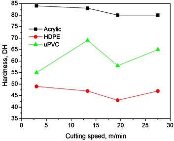
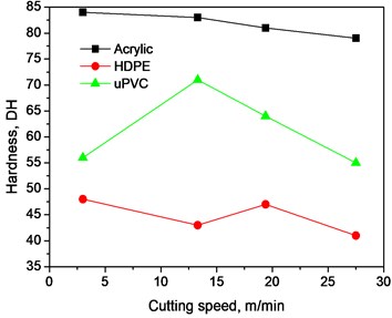
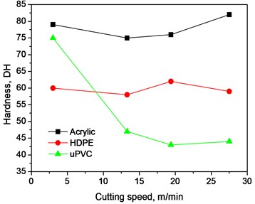
Fig. 5 shows the variation of hardness of the machined surface as a function of cutting speed for the selected depth of cuts. For all the states of cutting speeds and depth of cuts, Acrylic samples show the highest value of average surface hardness. The uPVC samples show higher surface hardness compared to those of HDPE samples except when highest depth of cut is used, where HDPE surfaces show higher average hardness unless very small depth of cut is used. It is also found that, with the increase of depth of cut, Acrylic assumes a declining trend in the hardness with cutting speed except at 4 mm depth of cut, where the values of hardness reach a certain minimum (15 m/min) and then again increases with increasing cutting speed. These variations in hardness are related to the generation of heat and distribution of shear stresses in the material. On average, the generation of heat increases with increase in cutting speed due to greater frictional power dissipation which causes the entanglement of the Acrylic chains to weaken. As a result, after cooling down the chains now have grater space among them and thus show less resistance to indentation. HDPE, on the other hand, shows a deviation from the decreasing trend with average hardness suddenly increasing at certain points instead of decreasing. This is because, unlike Acrylic, the magnitude of heat generation is much less due to its high specific heat capacity; here the role of shear forces is more dominant than that of Acrylic. HDPE under normal circumstances is ordered in parallel chins with only intermolecular forces present among them instead of physical chin entanglement as in the case of Acrylic. As a result, when subjected to machining both heat generation and plastic deformations influences surface conditions. At points of excessive plastic deformation, layers move past each other and deform the lattice in the form of strain hardening, thereby increasing the surface hardness. On the other hand, at points where temperature generation in more prominent for some reason, it has the effect of spreading the chains farther apart from their usual crystal structure, which leads to increasing intermolecular space, reducing intermolecular forces, thereby causing a decrease in hardness.
Fig. 5Variation of surface hardness with cutting speed at different depth of cut
a) 0.5 mm
b) 1.0 mm
c) 2.0 mm
d) 4.0 mm
For uPVC, the response is even more complicated as it has both types of structures, although amorphous zones are more prominent. In figures a, b and c there are points where the hardness suddenly increases followed by a decrease. Further, the points where hardness suddenly jumps are the points where the crystalline regions are strain-hardened, and the points where they suddenly fall are the points where the generation of increased heat causes amorphous zones to space out. In addition to that, uPVC is an atactic polymer with chloride groups in the chains, which make up the majority of its mass and are partially charged (Clδ+). Under normal conditions, some chloride groups of adjacent chains may be forced to stay together, however, this configuration is unstable as the repulsive forces mean that they are in a higher energy state compared to other elements in the structure. With the generation of enough heat however they are able to gain enough energy to move away from each other and reduce hardness. At higher depths of cut (2, 4 mm), increased cutting speeds lead to significantly increased heat generation, which causes both the crystalline and amorphous structures to spread out coupled with relatively lengthened time of cool down, thereby causing significant reduction in hardness.
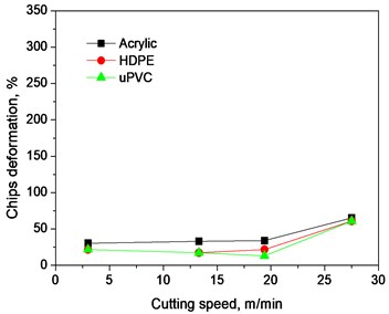
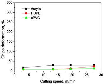
Fig. 6Variation of chips deformation with cutting speed at different depth of cut
a) 0.5 mm
b) 1.0 mm
c) 2.0 mm
d) 4.0 mm
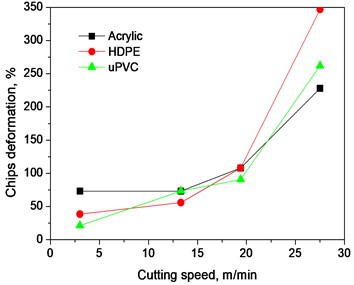
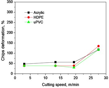
Fig. 6 describes the relationship between chip deformation and cutting speed at different depths of cut. For all the values of depth of cut, it is seen that the deformation increases with increasing cutting speeds. At higher depth of cut, the variation is low. HDPE has the highest average chip deformation compared to the other specimens, especially, at lower depths of cut (0.5 and 1 mm). Among the other two samples, uPVC shows marginally higher average chip deformation compared to Acrylic samples. This distinction, however, diminishes with increase in depth of cut, and at 2 mm depth of cut, all the curves almost coincide with one another giving nearly the same value of deformations for any particular cutting speed. The response of chip deformation with changing cutting speeds is also observed to be dependent on depth of cut. At lower depths of cut, the increase in chip deformation with cutting speed is almost exponential, while at higher depths of cut, the change in deformation gradually decreases, but no significant increase in chip deformation is observed with increasing cutting speeds when 4mm depth of cut is used. The increase in depth of cut also results in reduced average chip deformation. The chip material is likely to be exposed to high pressure and temperature near the tool-edge and flows more or less along the transverse direction to form the side flow [24, 25]. This behavior can be explained by the fact that, among the three materials HDPE is highly ductile as its chains are arranged in layers and there is no side branching, which, in turn, causes the layers to have a greater degree of movement between them with the application of shear stress, thereby causing greater average deformation. Moreover, HDPE is the material of least density among the three materials, due to absence of any high molecular weight side groups in the chains, which results in requiring less thermal energy to initiate deformation in spite of having the highest specific heat capacity. Again, looking at the coefficient of thermal expansion reveals that, for the same temperature increase, the linear expansion of HDPE is almost 10 times higher than that of Acrylic and uPVC. At lower depths of cut, the chips produced from uPVC are comparatively of lesser thickness and hence volume, thereby requiring less shear stress and heat to induce higher deformation. As the depth of cut increases, the material volume removed is increased along with its mass resulting in a need for greater heat generation to cause the same chip deformation. As a result, with increase in cutting speed, though the friction and hence heat increases due to greater surface of contact between the specimen and tool, it is not enough to generate the amount of heat required to cause a higher chip deformation, which eventually results in the reduction in chip deformation with increase in depth of cut as well as the diminished response to the increase in cutting speed for all three materials investigated [26].
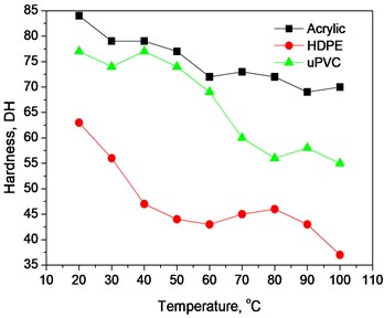
Fig. 7(a) shows the effect of real temperature on the hardness of the three polymers. A common trend for all the material is that, with the increase in temperature, the hardness of all the materials decreases nonlinearly. It can be seen that the average hardness of Acrylic is quite higher from that of uPVC, especially for high temperature ranges, but HDPE shows significantly less hardness compared to the other two materials. Acrylic shows a lower rate of hardness change with respect to temperature compared to that of uPVC, and the highest rate of change is observed for HDPE, particularly at lower and higher temperature ranges. It is well known that indentation hardness is a measure of the resistance of a material to permanent shape change. In this regard, it would have reaction to the microstructure of the material. HPDE is arranged in parallel chain layers which are able to deform plastically under load. That is why HDPE shows the least hardness among the three materials. Acrylic is almost fully amorphous and has higher number of entanglement junctions per unit volume and higher characteristic chain ratio compared to uPVC [27], resulting in high chain entanglement (and brittleness), which eventually results in almost no plastic deformation under applied loads. This may be considered as the basis for Acrylic to assume higher hardness compared to uPVC and HPDE. The mobility among the chains also affects hardness when subjected to temperature change. As the temperature increases, the HDPE chains are easily displaced and thus causes the hardness to reduce greatly. Since Acrylic chains are more entangled, less reduction in hardness is encountered with the increase of temperature.
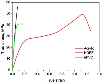
Fig. 7a) Variation of hardness with real temperature, and b) true stress strain curves
a)
b)
Fig. 7(b) shows the relations of true stress and true strain for the three polymeric materials. HDPE shows a high degree of plastic deformation before the break, while Acrylic shows no plastic deformation. uPVC shows very marginal plastic deformation. As discussed earlier, HDPE is structured in layers where each layer of chains can move relative to each other, giving rise to ductile characteristics, and hence it shows the highest plastic deformation followed by uPVC; lastly, Acrylic is very much brittle and hence no plastic deformation at all. The inability of Acrylic chains to move relative to each other eventually leads to the highest strength, however, HDPE sample undergoes strain hardening with the process of plastic deformation and shows the second highest strength, further increase beyond this point causes rupture among the molecules. uPVC deforms plastically for a very small portion of the total strain, because of which it is experiencing less crystalline areas [28, 29].
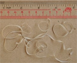
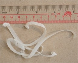
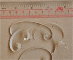
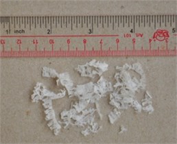
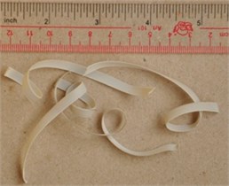
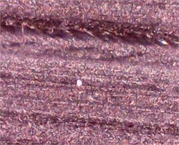
The behavior of HDPE is expected as it is fully ductile in nature because of its structure and so easily deforms plastically, even al lower stresses and thus gives coiled chains. Acrylic is almost fully material and so in the course of machining it produces fractured chips (continuous chips with BUE) due to its inability to plastically deform and at sufficiently high depths of cut gives fully discontinuous chips. In the case of uPVC discontinuity are less prominent in lower depths of cut as it can plastically deform to some extent. At highest depth of cut (4 mm) however it also shows the formation of cracked chips though the phenomenon is far less severe compared to Acrylic for the above-mentioned reasons. At the highest depth of cut and highest speed the disseverance of discontinuous chips and cracked chips of any type is due to two reasons; one being that uPVC is not fully amorphous so completely discontinuous chips are almost impossible to form for uPVC, the other being that at increased cutting speeds heat generation is grater leading to increased thermal softening and thus better chip formation. The types of produced chip can give important information on the machining. In the case peculiar of the plastics, it can happen two types of chips, the continuous and discontinuous. The continuous chips can be produced by a great elastic deformation or by a shearing action along a shear plan, occurring when small cutting speeds are used and in materials with a great strain. The shear plan will be in the direction in which the minimum work is demanded to form a chip, and the chips are continuous because the shear intervals are small. Different types of discontinuous chips can be formed when great compressive stresses are involved or when a brittle material is machined. It can also happen when a thermoplastic is machined at a large rake angle or a great cutting depth. This results in a fissure that extends down the point of the tool, and the chip is produced by the bending moment, which acts on the chip after the crack grow to some length. It is never observed when metals are cut, except for some kinds of cast iron [30]. As regard to the characterization of chips, Figs. 8 show the chips formed during machining of Acrylic, HDPE and uPVC at various cutting speeds and depths of cut. The chips of Acrylic generated due to slow cutting speed 3.0 m/min and 0.5 mm depth of cut are seen to be continuous and curly (Fig. 8(a)). It appears from the slip of chip that this is produced with BUE. Fig. 8(d) shows the chips of the same material produced at considerably higher velocity at 17.5 m/min. Though the chips are standard continuous chips, sufficient cracks are visible at the edges depending upon the brittleness of the chips. The chips of Acrylic at minimum velocity of 3.0 m/min and higher depth of cut 4.0 mm show some cracks in the edges of chips, but they are more continuous (Fig. 8(g)). At higher velocity and higher depth of cut produce discontinuous chips (Fig. 8(j)). Lack of ductility and high work hardening are noticed in the chips from Acrylic. It can be seen by Fig. 8(b, e, h, k), the change in the chip form for cutting speeds of 3.0 and 27.5 m/min and the depth of cut 0.5 mm and 4.0 mm shaping from HDPE to a spiral form. But the intensity of coil increases with the cutting speed. In case of uPVC (Fig. 8(c, f, i, l)), at a low cutting speed the chips have become curly as caused by BUE. At higher cutting speed, the curly nature of the chips changes and the chips become continuous but with cracks at the edges. Similar results also are shown for higher depth of cut. It is rather ductile and it can sustain a higher deformation at a high cutting speed without undergoing cracking at the edges. Curl radius was found to be related to the cutting speed for all depth of cut. Low cutting speed led to small chip curl radius while with increasing cutting speed, chip curl radius increased gradually. With increase of the cutting speed, the shearing bands become more and more intense with a considerable reduction in the width of contact between the segments up to fragment. This is attributed to the phenomenon of localized deformation in the primary shear zone that becomes more important with the increase in the temperature. The mechanical properties of material thus decrease in the cutting zone by reducing resistance to the plastic deformation and thus cause an abrupt shearing of the chip by creating a plastic instability [21]. With decreasing chip thickness and increasing curl radius, the effect of heat was diminished. The influence of heat on the thick chips with small curl radii can be explained by several factors. Firstly, the thick chips with small curl radii have comparatively less surface area than those with small thickness and big curl radius. This means less efficient heat dissipation especially when the chips are in contact with the tool.
Fig. 8Photo micrograph of the chips generated due to machining at different cutting speed and depth of cut
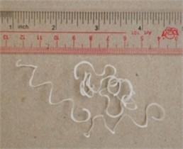
a) Acrylic 3.0 m/min at 0.5 mm
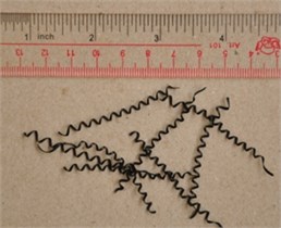
b) HDPE 3.0 m/min at 0.5 mm
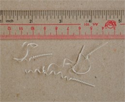
c) uPVC 3.0 m/min at 0.5 mm
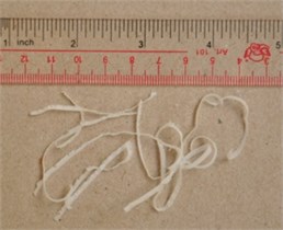
d) Acrylic 27.5 m/min at 0.5 mm
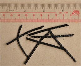
e) HDPE 27.5 m/min at 0.5 mm
f) uPVC 27.5m/min at 0.5 mm
g) Acrylic 3.0 m/min at 4.0 mm
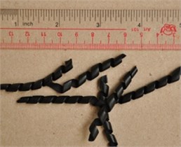
h) HDPE 3.0 m/min at 4.0 mm
i) uPVC 3.0 m/min at 4.0 mm
j) Acrylic 27.5 m/min at 4.0 mm
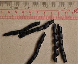
k) HDPE 27.5 m/min at 4.0 mm
l) uPVC 27.5 m/min at 4.0 mm
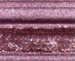
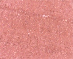
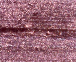
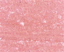
Fig. 9 shows the plastically deformed layers of the composites on the chip surfaces and the shear deformation characteristics after machining at different cutting speed and depth of cut. At a low cutting speed and different depth of cut, the chips surfaces of the material are very similar of the nature of relatively brittle. The areas created by crack propagation are evident. Microstructures reveal what was found earlier. Significant improvement for HDPE is found with increasing cutting speed with deep marks being present at lower cutting speeds and with the change being most noticeable at higher depths of cut. uPVC and Acrylic both show less improvement in surface texture in comparison to HPDE at higher cutting speeds. Also, indentation marks and deep grooves are less noticeable for both Acrylic and uPVC with both having almost the same intensity of scratches. However, it is seen that at 4 mm depth of cut and 27 m/min cutting speed Perspex shows small bumps spread throughout the surface. This is the effect of excessive heat generation causing gumping in the material. In general Perspex shows the best surface texture excluding the previous case only [31].
Fig. 9Optical microstructure of the surface generated due to machining at different cutting speed and depth of cut

a) Acrylic 3.0 m/min at 0.5 mm
b) HDPE 3.0 m/min at 0.5 mm

c) uPVC 3.0 m/min at 0.5 mm
d) Acrylic 27.5 m/min at 0.5 mm
e) HDPE 27.5 m/min at 0.5 mm

f) uPVC 27.5m/min at 0.5 mm
g) Acrylic 3.0 m/min at 4.0 mm
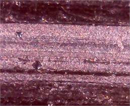
h) HDPE 3.0 m/min at 4.0 mm
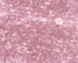
i) uPVC 3.0 m/min at 4.0 mm
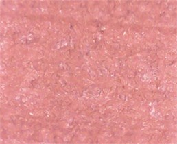
j) Acrylic 27.5 m/min at 4.0 mm
k) HDPE 27.5 m/min at 4.0 mm
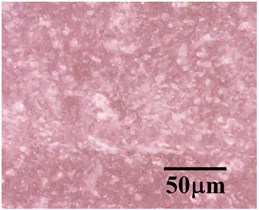
l) uPVC 27.5 m/min at 4.0 mm
4. Conclusions
Machined surfaces of some selected polymeric materials structures are investigated for their characterization as a function of different machining parameters. It is observed that higher cutting speed and low depth of cut ensures better surface finish for all the material samples. The temperature reduces the hardness of the composites due to nature of amorphous thermoplastic. For all three materials, the average chip-tool interface temperature is found to increase with the increase of cutting speed and depth of cut, in which the effect of cutting speed is more prominent for all the cases. Chips deformation is found to increase with cutting speed and depth of cut, although the role of cutting speed is identified to be more effective than depth of cut. Microstructures of the chips reveal that crack like flaws are formed at higher cutting speeds and higher depths of cut, and fewer cracks are observed at higher speeds and lower depths of cut. Among the three polymeric materials, Acrylic samples show better surface finish.
References
-
Salles J. L. C., Gonçalves M. T. T. Effects of Machining Parameters on Surface Quality of the Ultra High Molecular Weight Polyethylene (UHMWPE). Conamet/Sam-Simposio Materia, 2002.
-
Jagtap T. U., Mandave H. A. Machining of Plastics: A Review. International Journal of Engineering Research and General Science, Vol. 3, Issue 2, 2015, p. 577-581.
-
Brydson A. Plastics Materials. 7th edition, Butterworth-Heinemann, London, 1999.
-
Roy J. C. Plastics Engineering. 3rd edition, Butterworth-Heinemann, London, 1998.
-
Patton W. J. Plastics Technology: Theory, Design and Manufacture. Reston Publishing Company, Mumbai, 1986.
-
Dieter G. E. Materials Selection and Design. ASM international Handbook 20, USA, 1997.
-
Arbizu I. P., Perez C. J. L. Surface roughness prediction by factorial design of experiments in turning processes. Journal of Materials Processing Technology, Vol. 143, Issue 144, 2003, p. 390-396.
-
Choudhury I. A., El-Baradie M. A. Surface roughness prediction in the turning of high-strength steel by factorial design of experiments. Journal of Materials Processing Technology, Vol. 67, Issues 1-3, 1997, p. 55-61.
-
Dabnun M. A., Hashmi M. S. J., El-Baradie M. A. Surface roughness prediction model by design of experiments for turning machinable glass-ceramic (Macor). Journal of Materials Processing Technology, Vol. 164, Issue 165, 2005, p. 1289-1293.
-
Sahin Y., Motorcu A. R. Surface roughness model for machining mild steel with coated carbide tool. Materials and Design, Vol. 26, Issue 4, 2005, p. 321-326.
-
Chauhan S. R., Dass K. Optimization of machining parameters in turning of titanium (Grade-5) alloy using response surface methodology. Materials and Manufacturing Process, Vol. 27, Issue 5, 2012, p. 531-537.
-
Azlan M. Z., Habibollah H., Safian S. Simulated annealing to estimate the optimal cutting conditions for minimizing surface roughness in end milling Ti-6Al-4V. Machining Science and Technology, Vol. 14, Issue 1, 2010, p. 43-62.
-
Cakir M. C., Ensarioglu C., Demirayak I. Mathematical modeling of surface roughness for evaluating the effects of cutting parameters and coating material. Journal of Materials Processing Technology, Vol. 209, Issue 1, 2009, p. 102-109.
-
Bouacha K., Yallese M. A., Mabrouki T., Rigal J. F. Statistical analysis of surface roughness and cutting forces using response surface methodology in hard turning of AISI 52100 bearing steel with CBN tool. International Journal of Refractory Metals and Hard Materials, Vol. 28, Issue 3, 2009, p. 349-361.
-
Kobayashi A., Hirakawa K. Ultraprecision machining of plastics. Polymer-Plastics Technology and Engineering, Vol. 22, Issue 1, 1994, p. 15-25.
-
Arunkumar A., Prabaharan T. Optimization of cutting parameters in machining of polyphenylene sulphide composites. International Journal of Innovative Research in Science, Engineering and Technology, Vol. 3, Issue 3, 2014, p. 1082-1086.
-
Che-Haron C. H., Jawaid A. The effect of machining on surface integrity of titanium alloy Ti-6Al-4V. Journal of Materials Processing Technology, Vol. 166, Issue 2, 2005, p. 188-192.
-
Colafemina J. P., Jasinevicius R. G., Duduch J. G. Surface integrity of ultra-precision diamond turned Ti (commercially pure) and Ti alloy (Ti-6Al-4V). Journal of Engineering and Manufacture, Vol. 221, Issue 6, 2007, p. 999-1006.
-
Akhil C. S., Ananthavishnu M. H., Akhil C. K., Afeez P. M., Akhilesh R., Rajan R. Measurement of cutting temperature during machining. IOSR Journal of Mechanical and Civil Engineering, Vol. 13, Issue 2, 2016, p. 108-122.
-
Blake P. N., Scattergood R. O. Ductile-regime machining of germanium and silicon. Journal of the American Ceramic Society, Vol. 73, Issue 4, 1990, p. 949-957.
-
Korkut I., Kasap M., Ciftci I., Seker U. Determination of optimum cutting parameters during machining of AISI 304 austenitic stainless steel. Materials and Design, Vol. 25, 2004, p. 303-305.
-
Ciftci I. Machining of austenitic stainless steels using CVD multi-layer coated cemented carbide tools. Tribology International, Vol. 39, 2006, p. 565-569.
-
Bellenger V., Verdu J., Morel E. Effect of structure on glass transition temperature of amine crosslinked epoxies. Journal of Polymer Science Part B, Vol. 25, Issue 6, 1998, p. 1219-1234.
-
Davim J. P. Machining and machine-tools: research and development. 1st edition Woodhead Publishing, Cambridge, London, 2013.
-
Kishawy H. A., Elbestawi M. A. Effects of process parameters on material side flow during hard turning. International Journal of Machine Tools and Manufacture, Vol. 39, Issue 7, 1999, p. 1017-1030.
-
Liu R., Eaton E., Yu M., Kuang J. An investigation of side flow during chip formation in orthogonal cutting. Procedia Manufacturing, Vol. 10, 2017, p. 568-577.
-
Wu S. Control of intrinsic brittleness and toughness of polymers and blends by chemical structure: A Review. Polymer International, Vol. 29, Issue 3, 1992, p. 229-247.
-
Merah N., Saghir F., Khan Z., Bazoune A. Effect of temperature on tensile properties of HDPE pipe material. Plastics, Rubber and Composites, Vol. 35, Issue 5, 2013, p. 226-230.
-
Askeland D. R., Wright W. J. The Science and Engineering of Materials. 7th edition, Global Engineering, USA, 2015.
-
Kobayashi A. Ultraprecision Machining of Plastics. McGraw-Hill, New York, 1967.
-
Xiao K. Q., Zhang L. C. The role of viscous deformation in the machining of polymers. International Journal of Mechanical Sciences, Vol. 44, 2002, p. 2317-2336.
About this article

Thanks to Directorate of Advisory, Extension and Research Services of Bangladesh University of Engineering and Technology, Dhaka-1000 for providing the laboratory facilities.
