Abstract
This paper considers the calculation process for chip shape and cutting force of milling process in any direction of space.In the milling process with the existence of lead and tilt angle, the edges and boundary curves go through the process of one intersection, two intersections, tangency and non intersection in a milling cycle, thus the chip thickness needs to be calculated in various regions. The milling force is calculated by using the differential method. Then by comparing the milling forces when the lead angle is 5° and the tilt angle is 10° with when there is no inclination angle, the influence of inclination angle on machining process is studied. Meanwhile, by comparing the milling forces calculated by geometric analysis method with those calculated by classical Altintas model, the validity of the proposed method is verified. In addition, by comparing the milling forces obtained using the classical Altintas model with those obtained in published literature, the rationality of the method is further demonstrated.
Highlights
- A geometrical analysis method is proposed for calculating the engagement properties and chip thickness in milling process with lead and tilt angles.
- The effectiveness is verified by comparing the cutting forces of proposed model and Altintas model in published literature.
- Cutting forces can be reduced by increasing the inclined angles,resulting in improving the machining surface quality.
1. Introduction
The calculation of milling force for ball end milling cutter is an important step to estimate the dynamic stability and improve the surface quality in five axis machining process. Since there is an inclination angle between the cutter axis and the normal direction of the workpiece surface , so the milling force model is more complicated. Se [1] calculated the milling force in , and directions with an inclination angle by using the coordinate transformation method. Altintas [2] calculated the start and exit angle of each cutting edge element with the existence of lead and tilt angle, thus aquiring the milling force. Fard [3] conducted experiments on the milling process of ball end milling cutter with the same lead angle and different tilt angles, and found that the lead angle had greater impact on the surface roughness. Chen [4] determined the optimized cutting direction by calculating the interference area between the tool and the workpiece. Urbikain [5] studied the dynamic stability in milling process under different lead and tilt angles, and found that the milling stability was very sensitive to the inclination angle. Yuan [6] designed the tool orientation without interference in the engagement, and thus generated a smooth machining path. Huang [7] achieved the optimization of tool posture by solving the problem of minimization of milling force in the direction of maximum blade deformation. Liu [8] implemented the micro milling experiment of KDP crystals and found that the surface roughness was lower when the positive lead angle was adopted. Chen [9] carried out an experiment study on the cutting surface roughness under different lead angles and found that the machining surface would have more defects when the lead angles were below 15°. In this paper, the chip thickness is calculated when the cutting edge line and chip boundary curve have one intersection point, two intersection points, one tangent point and no intersection point. Then the milling forces with inclination angle is calculated by using the differential method. By comparing the milling forces calculated by the method in the paper with those calculated by the Altintas model in the published literature, the validity of the proposed method is verified.
2. Milling model in any direction of space
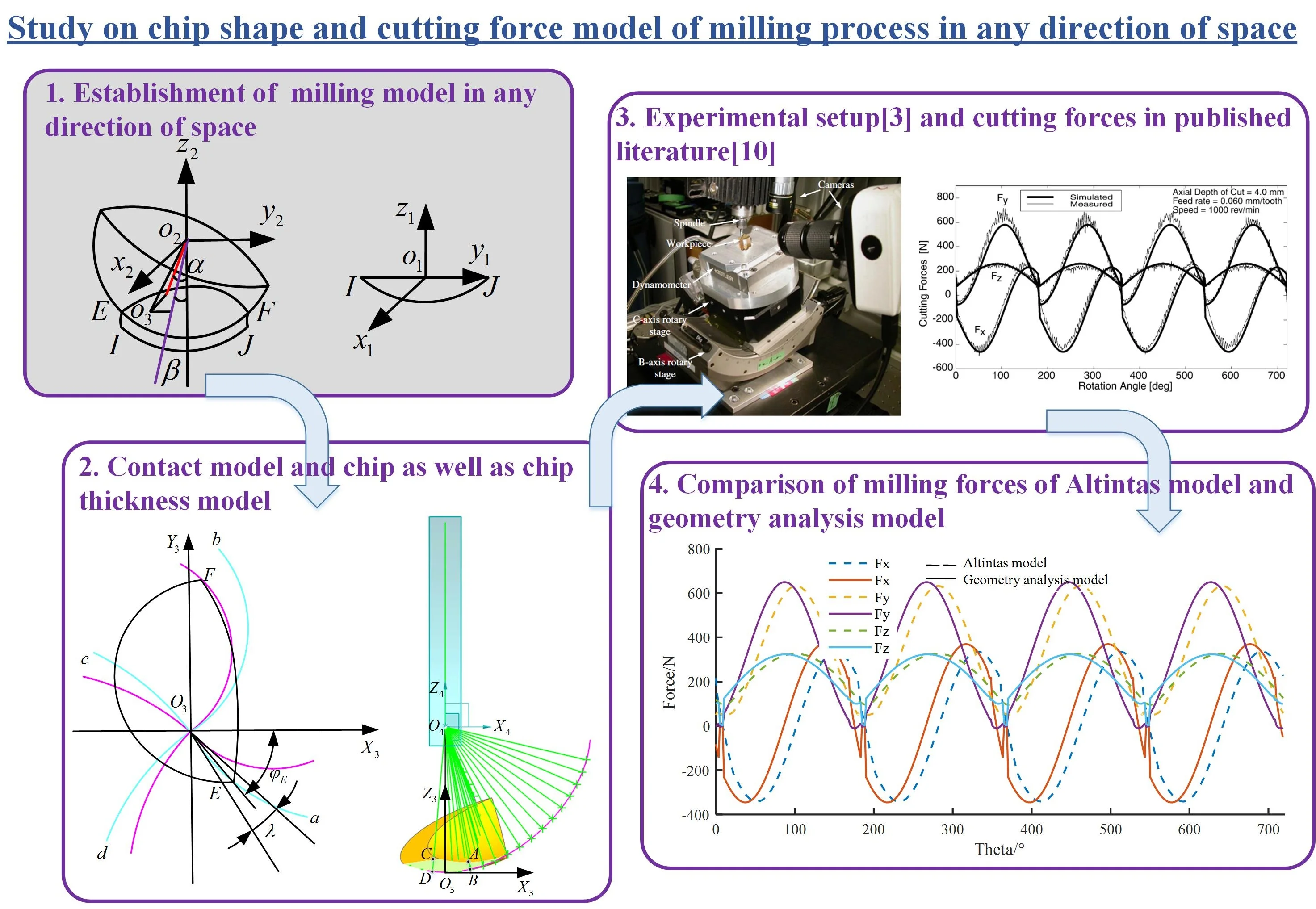
The milling model in any direction of space was established, and two inclination angles were adopted, including lead angle and tilt angle , as are shown in Fig. 1. The coordinate system is established by taking the midpoint of line of the cutting area as the origin. Set the contact sphere between the ball end milling cutter and the workpiece after the first feed as sphere 1, and that after the second feed as sphere 2. The coordinate system is established by regarding the center of sphere 2 as the origin, then the intersection of four edge lines of sphere 2 is the origin of coordinate system , and the axis coincides with the cutter axis. Point and are the intersection points of sphere 1, sphere 2 and the workpiece surface.
Fig. 1Milling model in any direction of space
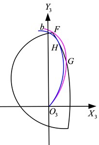
3. Geometry contact model between the edge line and boundary curve
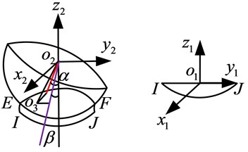
The chip geometric model is shown in Fig. 2. In Fig. 2, when the chip thickness model only crosses the sphere, the geometry model is . When the chip thickness model crosses both the plane and the sphere, the geometry model is . Set up a coordinate system paralleling to the coordinate system at the center of the sphere 2. There are three types of contact cases between the cutter edge lines and chip boundary curves, which including intersection, tangency and no intersection, as are shown in Fig. 3 and Fig. 4.
Fig. 2Chip geometry model
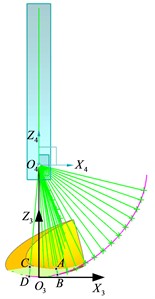
Fig. 3Intersection model
Fig. 4Tangent model
4. Chip thickness model
4.1. Chip thickness calculation
In the presence of lead and tilt angle, the chip geometry model of cutting tool with four edge lines is shown in Fig. 3 and Fig. 4. Set up a coordinate system parallel to the coordinate system at the center of the sphere 1. In order to calculate the chip thickness at a point on the cutting edge line, it is necessary to obtain the equation of the surface where point is located and the equation of the curve where point is located. The surface where point is located is sphere 1, which is translated from sphere 2 by the vector . The curve where point is located is the cutter edge line.
In order to solve the equation of the sphere where point is located, the transformation between the coordinate system and should first be obtained, and it is expressed as following:
Within that:
The coordinates of sphere center in the coordinate system is , then the coordinates in the coordinate system are:
And the equation of sphere 1 is:
The point satisfies the Eq. (4), and the variable ,, in Eq. (4) is the coordinates on sphere 1.
The point satisfies the equation of cutter edge line, and the coordinates of point are:
Within Eq. (5), is the angle between point and axis .
Then the equation of line is:
In which the variable , , in Eq. (6) are the coordinates on the line , , , are the coordinates on the cutter edge line.
By combining Eq. (4) and Eq. (6), the coordinates of point can be obtained, and the chip thickness can be calculated.
If the chip thickness geometric model is , and since passes through the plane, the equation of the plane needs to be calculated. And then the chip thickness can be aquired.
4.2. Calculation of tangent points
By calculating the tangent vector of the cutter edge line and boundary curve, the tangent point of two curves can be calculated. The equation of the cutter edge line is Eq. (5), then the tangent vector is:
The boundary curve is the intersecting circle of sphere 1 and sphere 2, then the tangent vector of the boundary curve is:
Let the tangent vectors of the two curves be equal, that is , then the tangent point can be solved out.
5. Milling force calculation
By calculating milling forces on different edge lines, the milling forces of the cutter in coordinate system can be obtained. The cutter parameters and milling force coefficients [10] are shown in Table 1.
Table 1Cutter parameters and milling force coefficients
Variables | Value | Variables | Value |
Radius | 6 mm | 17.29 | |
Helix angle | 30° | 2172.1 | |
Number of edge curves | 2 | 7.79 | |
Lead angle/tilt angle | 5°/10° | 848.9 | |
Cutting depth | 2 mm | –6.63 | |
Feed rate | 0.5 mm/z | –725.07 |
Thus, the milling forces in , and directions can be obtained through integration,and the simulation results are shown in Fig. 5.
Fig. 5Milling forces for Fx, Fy and Fz: ap= 4 mm, lead angle α= 5°, tilt angle β= 10°, f= 0.06 mm
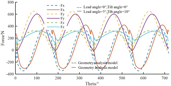
As can be seen from Fig. 5, when the lead angle is 5° and the tilt angle is 10°, the variation trend of milling forces in , and directions is the same as that without inclination angle, but the amplitude of milling force in and directions are lower than that without inclination angle, while the amplitude of milling force in direction is basically the same as that without inclination angle. It shows that by increasing the lead and tilt angle in the milling process, the milling force can be reduced, thus changing the machining difficulty and improving the machining surface quality.
6. Experiment verification
In order to verify the simulation results, the results of published literatures are used for comparison. The milling test can refer to the experiment in Fig. 6, the comparison results of simulations are shown in Fig. 7 and Fig. 8. An experiment designed by M. Javad Barakchi Fard of the reference [3] was used to describe the milling and testing process. The experiment is conducted on a five axis machining center in which the copper was processed by a two edge ball end milling cutter and the milling forces are measured through a Kistler sensor.
Fig. 6Experimental setup [3]
![Experimental setup [3]](https://static-01.extrica.com/articles/23296/23296-img6.jpg)
Fig. 7Measured and predicted cutting forces for slot cutting [10]
![Measured and predicted cutting forces for slot cutting [10]](https://static-01.extrica.com/articles/23296/23296-img7.jpg)
Fig. 8Milling forces of Altintas model and geometry analysis model
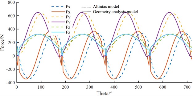
It can be seen from Fig. 8 that the milling forces calculated by geometric analysis method in this paper are basically consistent with those calculated by classical Altintas model, thus verifying the effectiveness of the method proposed in this paper. At the same time, by comparing the milling forces calculated by the classical Altintas model in this paper with the calculation and test results in the published literature [10], as is shown in Fig. 7, it can be found that they keep good consistency, which further verifies the rationality of the geometric analysis method adopted in this paper.
7. Conclusions
In this paper, the contact model between the cutting edge and chip in five axis machining process with lead angle and tilt angle is studied by geometric analysis method, and the milling forces are calculated. The results are compared with those of published literatures. The conclusions in this paper are as following:
1) When the lead angle is 5° and tilt angle is 10°, the change trend of milling forces in , and direction is the same as that without inclination angle, but the amplitude of milling forces in and direction decrease compared with that of lead and tilt angle is 0°. Therefore, the milling forces can be reduced by changing the lead and tilt angle, thus improving the surface quality in the machining process.
2) The milling forces calculated by geometry analysis model are basically consistent with those calculated by Altintas model, which verifies the validity of the method adopted in this paper.
3) By comparing the calculation results of Altintas model in the paper with those of published literature, the rationality of the method in the paper is further explained.
References
-
S. E. Layegh K., I. E. Yigit, and I. Lazoglu, “Analysis of tool orientation for 5-axis ball-end milling of flexible parts,” CIRP Annals, Vol. 64, No. 1, pp. 97–100, 2015, https://doi.org/10.1016/j.cirp.2015.04.067
-
C. Sun and Y. Altintas, “Chatter free tool orientations in 5-axis ball-end milling,” International Journal of Machine Tools and Manufacture, Vol. 106, pp. 89–97, Jul. 2016, https://doi.org/10.1016/j.ijmachtools.2016.04.007
-
M. J. B. Fard and E. V. Bordatchev, “Experimental study of the effect of tool orientation in five-axis micro-milling of brass using ball-end mills,” The International Journal of Advanced Manufacturing Technology, Vol. 67, No. 5-8, pp. 1079–1089, Jul. 2013, https://doi.org/10.1007/s00170-012-4549-6
-
K.-H. Chen, “Investigation of tool orientation for milling blade of impeller in five-axis machining,” The International Journal of Advanced Manufacturing Technology, Vol. 52, No. 1-4, pp. 235–244, Jan. 2011, https://doi.org/10.1007/s00170-010-2701-8
-
G. Urbikain, D. Olvera, and L. N. L. de Lacalle, “Stability contour maps with barrel cutters considering the tool orientation,” The International Journal of Advanced Manufacturing Technology, Vol. 89, No. 9-12, pp. 2491–2501, Apr. 2017, https://doi.org/10.1007/s00170-016-9617-x
-
C. Yuan, Z. Mi, X. Jia, F. Lin, and L. Shen, “Tool orientation optimization and path planning for 5-axis machining,” Journal of Systems Science and Complexity, Vol. 34, No. 1, pp. 83–106, Feb. 2021, https://doi.org/10.1007/s11424-020-9270-1
-
T. Huang, X.-M. Zhang, and H. Ding, “Tool orientation optimization for reduction of vibration and deformation in ball-end milling of thin-walled impeller blades,” Procedia CIRP, Vol. 58, pp. 210–215, 2017, https://doi.org/10.1016/j.procir.2017.03.211
-
Q. Liu, J. Cheng, Y. Xiao, M. Chen, H. Yang, and J. Wang, “Effect of tool inclination on surface quality of KDP crystal processed by micro ball-end milling,” The International Journal of Advanced Manufacturing Technology, Vol. 99, No. 9-12, pp. 2777–2788, Dec. 2018, https://doi.org/10.1007/s00170-018-2622-5
-
X. Chen, J. Zhao, Y. Dong, S. Han, A. Li, and D. Wang, “Effects of inclination angles on geometrical features of machined surface in five-axis milling,” The International Journal of Advanced Manufacturing Technology, Vol. 65, No. 9-12, pp. 1721–1733, Apr. 2013, https://doi.org/10.1007/s00170-012-4293-y
-
S. Engin and Y. Altintas, “Mechanics and dynamics of general milling cutters,” International Journal of Machine Tools and Manufacture, Vol. 41, No. 15, pp. 2195–2212, Dec. 2001, https://doi.org/10.1016/s0890-6955(01)00045-1
About this article

This research was funded by the National Natural Science Foundation of China Grant No. 51875005.
The datasets generated during and/or analyzed during the current study are available from the corresponding author on reasonable request.
The authors declare that they have no conflict of interest.
