Abstract
Aiming at the problem of insufficient power supply in modern intelligent fuze, it is of great theoretical significance and practical guidance to study the relationship between acoustic vibration response and power generation characteristics of airborne piezoelectric generators and maximum energy output. Theoretical analysis and experimental verification show that: 1. As long as the frequency of the acoustic wave induced by the flow coincides with the frequency of the acoustical modal in the cavity, a sinusoidal vibration excitation signal will be generated in the cavity; 2. With the increase of the flow rate, the frequency of the vibration signal coupled by the fluid sound source also increases. If the frequency of the acoustic wave is near the anti-resonance frequency of the piezoelectric vibrator, the displacement amplitude of the piezoelectric vibrator increases greatly. The maximum output open circuit voltage is the maximum power generated when the external circuit is connected; 3. The amplitude of the open circuit voltage of the electromechanical coupling output is linear with the amplitude of the displacement of the piezoelectric vibrator, the frequency is the same, the phase angle is the same, and the displacement and the exciting force of the piezoelectric vibrator have the characteristics of the same frequencies and backward phases, the maximum displacement of the piezoelectric vibrator is related to the amplitude of the exciting force and the angular frequency of the exciting force. This characteristic can be used to solve the piezoelectric stress factor under different initial conditions from the experimental point of view.
Highlights
- When the acoustical modal frequency in the resonant cavity is consistent with the frequency of the flow induced acoustic wave, the regular vibration signal can be generated
- The maximum energy output of the generator: the pulsative sinusoidal excitation frequency coupled in the resonant cavity is consistent with the anti-resonant frequency of the piezoelectric vibrator
- Calculate the piezoelectric stress factor from the perspective of experiment
- The interface circuit can be designed according to the frequency and amplitude of the acoustic wave and the vibration frequency and amplitude of the piezoelectric vibrator
- The vibration displacement of piezoelectric vibrator is the same as the frequency of the open circuit voltage
1. Introduction
The detonation of electric detonators in modern intelligent fuse, the reception and processing of fuse signals, the control of ignition and the increase in the number and types of sensors make the power demand of the fuse circuits to be higher and higher, therefore the problem of insufficient power supply, and less available power source have become one of the difficulties in research of modern intelligent fuse. The airflow acoustic piezoelectric generator can use the air against the projectile during the flight and convert the environmental energy during the flight into a pulsating sinusoidal vibration excitation [1, 2], and then output power through the transducing mechanism. Thus, the airflow acoustic piezoelectric generator is one of the new fuse power sources that can effectively solve the problem of insufficient power supply for fuse. Therefore, it is of great significance to study the relationship between acoustic vibration response and power generation characteristics of the airflow acoustic piezoelectric generator and the output of the maximum energy.
Chen Hejuan and Li Yingping referred to the jet generator in the US military manual, studied and improved its theory. Being the first to propose the airflow acoustic piezoelectric generator [3], Chen Hejuan, Zhu Xiaoguang, Zou Huajie et al. pioneered the development of small vibration piezoelectric generator principle prototype [4, 5], Wang Gensheng discovered the frequency characteristics of the air acoustic piezoelectric generator through experiments, and provided guidance for the circuit design [6]. However, he did not further study the sound pressure amplitude and voltage amplitude of the generator; Wang Junlei et al. studied the influence of external load on the energy conversion of vortex-induced vibration in a three-phase coupled cylinder, used the matrix method to analyze the system damping and the natural frequency of the vibration energy, and obtained the steady-state equation [7], of the system voltage output mainly through software simulation, however there was no experiment to verify the accuracy of the theoretical. Zou Huajie proposed experimental analysis and estimation method for the vibration frequency problem of the existing airflow acoustic piezoelectric generator [8, 9], without studying the effect of acoustic vibration response on the transduction. By studying the acoustic vibration response of the fluid sound source, this article has achieved the transducer process from fluid-acoustic wave-vibration-power under the action of force, displacement and acceleration of vibration source of the pickup transducer system, and successfully tracked the exciting force, piezoelectric vibrator and the changes of amplitude, frequency and phase of the open circuit voltage during the coupling process. At last, the correctness of the theory was verified by experiments, which provided a new research idea for studying the phenomenon of airflow acoustic.
2. Working principle of airflow acoustic piezoelectric generator
The schematic diagram of the structure of the air acoustic vibration piezoelectric generator is shown in Fig. 1. The system mainly consists of three parts: the airflow regulating mechanism, the airflow acoustic mechanism, and the acoustic-electrical conversion mechanism. The airflow regulating mechanism includes air inlet duct and annulus, the external airflow is injected from the air inlet duct and pass through the annulus to form turbulent with uniform velocity field near the air inlet, which will shed off after forming vortex [1] at the outlet of the nozzle. The airflow acoustic mechanism includes wedge and resonant cavity. the vortex shedding formed at the nozzle outlet of the airflow regulating mechanism induces pulsating pressure field to impact the wedge, which will form edge sound, that is, a high frequency small amplitude fluid dynamic sound source is formed. As total reflection is formed when the sound wave contacts with the piezoelectric vibrator at the bottom of the resonant cavity, thereby there is stable standing wave formed in a short time, as a result, the sound intensity in the resonant cavity is amplified. The acoustic-electric conversion mechanism includes resonant cavity and piezoelectric vibrator. The stable standing wave in the resonant cavity acts like a spring to make the piezoelectric vibrator carry out simple harmonic vibration, thereby making the piezoelectric vibrator to release electric energy.
3. Acoustic vibration and power generation characteristics of airflow acoustic piezoelectric generator
3.1. Acoustic vibration response
According to the literature [8], the acoustic frequency and the acoustical modal frequency 𝜔𝑠 can be expressed as:
where is the Reynolds number, is the diameter, and , , and are the length, diameter, and Resonant cavity to nozzle distance of the resonant cavity respectively.
Airflow acoustic vibration piezoelectric generator is a fluid oscillation controlled by the acoustic standing wave modal of the cavity. The expression of acoustic pressure in the cavity [5] is:
where 𝑝𝑚 is the amplitude of the acoustic pressure.
Fig. 1Schematic diagram of airflow acoustic vibration piezoelectric generator
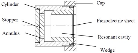
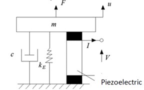
Fig. 2General basic excitation type piezoelectric transformation model
3.2. Power generation characteristics
The electromechanical energy conversion process is shown in Fig. 2, which is similar to a general basic excitation type piezoelectric conversion type with a piezoelectric vibrator. The dynamic equation of the system shown in Fig. 2:
where is the equivalent mass of the airflow acoustic vibration piezoelectric generator, is the equivalent stiffness of the mechanical part of the generator, is the resultant force, is the mechanical damping coefficient of the generator, and is the displacement of the piezoelectric vibrator. Solve to obtain:
Since 𝛽 is the system damping coefficient, and are constant terms. As makes tend to 0 in a short time, therefore the displacement of the piezoelectric vibrator can be equivalent to the displacement of , i.e.:
where is the amplitude of the displacement, 𝜑 is the phase angle, , when the maximum value is obtained, which is the maximum, at this time.
The thickness of the piezoelectric vibrator is much smaller than the radius and is telescopically vibrating along the direction of thickness. The boundary condition of the piezoelectric vibrator is mechanical clamping and is in an open circuit state. Assuming no leakage, the piezoelectric equation of the piezoelectric vibrator is:
In the equation, is the open circuit elastic stiffness constant, N/m2; is the piezoelectric stiffness constant, N/m; is the clamping dielectric isolation rate, m/F.
Substituting Eq. (7) into Eq. (4) to obtain:
In the open circuit state, the current is zero, so there will be:
where is the static clamping capacitance, is the piezoelectric stress factor.
In summary, when the piezoelectric vibrator is in an open circuit state, the mechanical quantity and the electrical quantity and their relationship can be expressed as:
It can be seen from Eq. (10) that the voltage frequency, the vibration frequency of the piezoelectric vibrator and the excitation force frequency are consistent, the displacement of the piezoelectric vibrator and the open circuit voltage phase are consistent and they are backward the excitation force; in order for higher voltage output of the piezoelectric vibrator, it is necessary to increase the amplitude value of the displacement , when , , for airflow acoustic vibration piezoelectric generator, there are two ways to increase the amplitude of the displacement:
First: Ensure the relationship between the acoustic wave angular frequency and the antiresonance frequency of clamped piezoelectric vibrator to be ,to bring the system to resonance;
Second: Increase the flow rate to increase the amplitude of the excitation force value .
4. Experiments
4.1. Acoustic vibration response
The impedance test of the air acoustic vibration piezoelectric generator was carried out, result has shown that the anti-resonance frequency of piezoelectric oscillator is 6.37 kHz. The testing curve is shown in Fig. 3.
Fig. 3Anti-resonant frequency of piezoelectric vibrator under clamping state
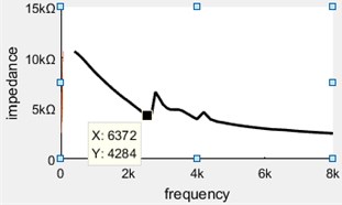
Fig. 4 shows the waveform diagram and spectrum analysis diagram of the flow rate of 79.79 m/s, the frequency relationship diagram shown in Fig. 5 was obtained according to the recorded data from the waveform diagram and spectrum analysis diagram.
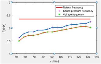
It can be seen from Fig. 5 that as the flow rate increases, the acoustic pressure frequency in the resonant cavity increases gradually, meanwhile the open circuit voltage frequency of the generator is also increasing gradually, which is slightly less than the increment of the sound pressure frequency, but the error range is within 4 %, therefore it can be nearly considered that the sound pressure frequency and the voltage frequency are consistent, and the main cause of the error is the difference of the end caps of the generator when measuring the sound pressure and the open circuit voltage.
Fig. 4Sound pressure waveform and spectrum analysis chart with flow rate of 79.79 m/s
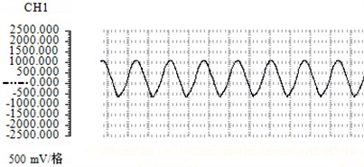
a) Sound pressure waveform
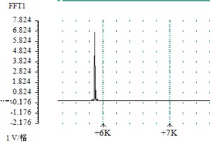
b) Spectrum analysis
Fig. 5Airflow induced vibration piezoelectric generator frequency relationship diagram
4.2. Power generation characteristics
Record the peak-to-peak values of the open circuit voltage at the 16 types of flow rates, and make the relationship diagram between the open circuit voltage and the flow, as shown in Fig. 6.
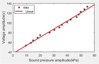
Compared the peak-to-peak value of the open circuit voltage with the peak-to-peak value of the acoustic pressure, as shown in Fig. 7.
It can be seen from Fig. 6 that the peak-to-peak value of the open circuit voltage reached its maximum at the flow rate of 127.7 m/s, the voltage frequency was 6.016 kHz as shown by the data acquisition card. Therefore, the amplitude of the open circuit voltage reaches its maximum before the anti-resonant frequency of the piezoelectric vibrator reaches 6.37 kHz.
From the obtained curve in Fig. 7, it can be seen that the pick-to-pick value of the open circuit voltage is positively correlated with the peak-to-peak value of the acoustic pressure.
Fig. 6Flow rate versus voltage
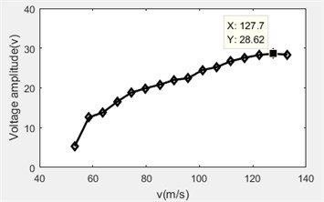
Fig. 7Sound pressure and voltage
5. Conclusions
1) When designing the gas acoustic pezioelectric generator, only when the acoustical modal frequency in the resonant cavity is consistent with the frequency of the flow induced acoustic wave, the regular vibration signal can be generated.
2) Requirements for the maximum energy output of the generator: the pulsative sinusoidal excitation frequency coupled in the resonant cavity is consistent with the anti-resonant frequency of the piezoelectric vibrator under clamped state. Practically, due to the existence of system damping, the frequency of sinusoidal excitation signal is slightly smaller than the anti-resonance frequency of the piezoelectric vibrator in the clamped state.
3) Calculate the piezoelectric stress factor from the perspective of experiment, directly measure the data through experiments, avoid considering the initial conditions of the piezoelectric vibrator, the piezoelectric stress factor can be obtained according to formula:
4) The acoustic wave frequency, the vibration frequency of the piezoelectric vibrator, and the open circuit voltage frequency are consistent, and the amplitudes are proportional. The interface circuit can be designed according to the frequency and amplitude of the acoustic wave and the vibration frequency and amplitude of the piezoelectric vibrator.
5) The vibration displacement of piezoelectric vibrator is the same as the frequency of the open circuit voltage, and the phase angles are consistent. The extreme value of the vibration displacement of the piezoelectric vibrator can be obtained by measuring the open circuit voltage.
References
-
He Peng Numerical Simulation of Flow Field in the Air Inlet of Airflow Control of Fuze New Type of Missile-Borne Piezoelectric Generator. Nanjing University of Science and Technology, 2012.
-
Liu Fei Numerical Simulation and Experimental Analysis of Airflow Excitation Inlet Duct of Airflow Acoustic Generator. Nanjing University of Science and Technology, 2016.
-
Li Yingping Principle and Experimental Research of Fuze Piezoelectric Generator. Nanjing University of Science and Technology, 2006.
-
Zhu Xiaoguang Air-Induced Vibration Excitation Technology of Small Vibration Piezoelectric Generator and Its Experimental Research. Nanjing University of Science and Technology, 2015.
-
Zou Huajie, Chen Hejuan, Liang Yi, Jiang Qi, Liu Bin, Wang Junhong The airflow acoustic excitation characteristics research of fuze vibration piezoelectric generator. Ordnance Science Newspaper, Vol. 36, Issue 4, 2015, p. 610-618.
-
Gensheng Wang, Jianyu Cai, Jiacun Sun, Huajie Zou, Hejuan Chen Vibration model and frequency characteristics of the piezoelectric transducer in airflow-induced acoustic generator. Journal of Vibroengineering, Vol. 20, Issue 1, 2018, p. 591-601.
-
Wang Junlei Model and Characteristics of Vortex-Induced Vibration Energy Collection Based on Flow-Electro-Mechanical Multi-Physical Fields Coupling. Chongqing University, 2014.
-
Zou Huajie, Zhang Jianghua, Chen Hejuan Experimental analysis and estimation of vibration frequency of piezoelectric generator excited by airflow. Journal of Detection and Control, Vol. 39, Issue 6, 2017, p. 35-39.
-
Zou Hua-Jie, Chen He-Juan Frequency characteristic of piezoelectric generator based on airflow induced sound. Journal of Chemical and Pharmaceutical Research, Vol. 7, Issue 3, 2015, p. 1328-1334.
-
Min Qi Research on the Characteristics of Detuned Standing Wave Tube and the Nonlinear Standing Wave Field in the Tube. Science Press, Beijing, 2017.
About this article

