Abstract
The acoustic energy collector uses the cavity acoustic mode to capture the acoustic signal in a certain frequency range at the mouth of the cavity, achieves fluid-solid coupling and amplifies the acoustic vibration excitation, and then through piezoelectric, magnetoelectric and friction power generation mechanisms, the acoustic energy is finally converted into electrical energy. The overview of the research progress of cavity-based acoustic energy harvesters has found that acoustic energy harvesters are usually composed of resonant cavity, diaphragm, and transducer materials, and the resonant cavity is the key to the design of acoustic energy harvester. Analyze the influence of cavity structure on sound pressure amplification to provide reference for the research and application of acoustic energy harvester. The piezoelectric type is the main energy conversion method, the magnetoelectric type is the auxiliary, and the friction power generation and the acoustic crystal resonance power generation have also become a new research direction, because of the widest application range of hybrid power generation, it has become a future development trend.
Highlights
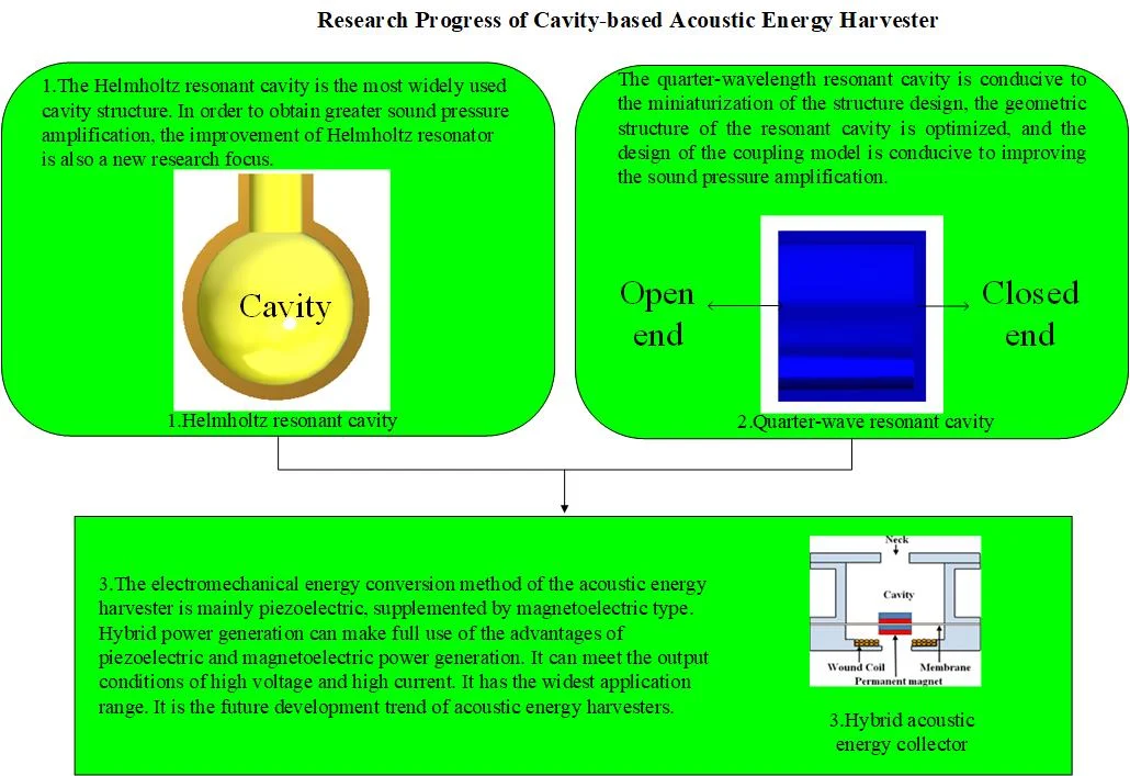
- The Helmholtz resonant cavity is the most widely used cavity structure. In order to obtain greater sound pressure amplification, the improvement of Helmholtz resonator is also a new research focus.
- The quarter-wavelength resonant cavity is conducive to the miniaturization of the structure design, the geometric structure of the resonant cavity is optimized, and the design of the coupling model is conducive to improving the sound pressure amplification.
- The electromechanical energy conversion method of the acoustic energy harvester is mainly piezoelectric, supplemented by magnetoelectric type. With the emergence of new technologies and new materials, friction power generation and acoustic crystal resonance power generation have become a new research direction. Hybrid power generation can make full use of the advantages of piezoelectric and mag
1. Introduction
The development and use of new energy, especially renewable energy, has become the principle of energy construction and development in various countries, and the research on environmental energy harvesters is a major research hotspot [1].
The acoustic energy collector uses the cavity acoustic mode to capture the acoustic signal in a certain frequency range at the mouth of the cavity, achieves fluid-solid coupling and amplifies the acoustic vibration excitation, and then through piezoelectric, magnetoelectric and friction power generation mechanisms, the acoustic energy is finally converted into electrical energy. In the fields of aerospace, weapon equipment, marine engineering, etc., cavity structures exist widely [2]. When the high-speed jet passes through the cavity, vortex-induced vibration will occur in the cavity, forming a feedback growth loop, which will cause the energy to be continuously converted into the sound field, if the sound field energy is collected, the damage caused by the sound radiation to the mechanical structure can be effectively reduced, at the same time, energy waste can be avoided, so the research of acoustic energy harvester has important academic value and engineering application background. For example, in terms of engineering applications, the research of acoustic energy harvesters can effectively reduce the damage of the cavity near-field acoustic radiation to the electronic instruments and meters in the weapon compartment.
The generation of airflow-induced sound is closely related to the phenomenon of vortex-induced vibration, and vortex-induced vibration is mainly affected by the geometry of the resonant cavity and the incoming flow parameters [3], so the resonant cavity is the key to the design of acoustic energy harvesters. At present, mainstream resonators include Helmholtz resonators, quarter-wavelength resonators and half-wavelength resonators, which can be divided into deep cavities and shallow cavities according to the depth of the cavity in the resonator [4].
The cavity-based acoustic energy harvesters can be classified by energy conversion methods, including piezoelectric effect, electromagnetic induction, friction power generation, and acoustic crystal resonance power generation [5].
2. Energy harvesting mechanism
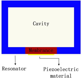
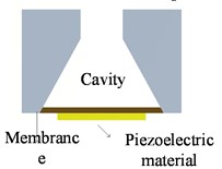
The cavity-based acoustic energy harvester converts acoustic energy into vibration energy and then converts vibration energy into electrical energy through piezoelectric effect, electromagnetic induction, and friction power generation for users to use [6], [7]. A typical acoustic energy harvester is usually composed of a resonator, a cavity, a diaphragm and a piezoelectric material, as shown in Fig. 1.
Fig. 1Schematic diagram of typical acoustic energy collector
Since 1950, the United States and Russia have begun to conduct research on cavity-based energy harvesters [8]. For example, in 1960, Harry Diamond et al. in the United States invented the airflow resonance generator [9], also known as a jet generator, and it was applied in the military field as a fuze power supply.
(1) Analysis of sound mechanism caused by airflow.
The phenomenon of sound caused by airflow in a cavity is a very complex dynamic system, and there are many explanations for the generation of sound sources. The current research on the internal and external description, excitation and control mechanism of aerodynamic sound sources is still in the exploratory stage. However, it is generally believed that the generation of sound sources in the cavity mainly includes the following four links, forming a closed-loop system, as shown in Fig. 2. When the high-speed jet passes through the static fluid medium, the boundary of the jet and the static medium will continuously generate vortices. The vortex follows the jet and encounters sharp objects, which stimulates more vortices and produces sound at the same time. When the acoustic signal propagates to the bottom of the resonant cavity, it is reflected. At this time, the acoustic signal is fed back to the flow field, and at the same time has an effect on the vortex shedding to adjust the new vortex frequency to be consistent with the acoustic mode frequency. Due to the resonance phenomenon, the induction and radiation of the sound source in the cavity are further amplified.
The cavity geometry is an important factor affecting sound production, and different cavities have different sound pressure amplification capabilities. At present, the cavity mainly includes four types: Helmholtz resonant cavity, half-wavelength resonant cavity, quarter-wavelength resonant cavity, and other cavity structures.
The development of computer technology has promoted the progress of computer fluid mechanics and acoustic calculations. More and more scholars have begun to try to use numerical methods to study aeroacoustic problems. There are three commonly used numerical methods to explain aeroacoustics: computational aeroacoustics method [12], Lighthill acoustic analog method [13] and hybrid calculation method [15], [16].
Fig. 2The process of acoustic generation in a cavity
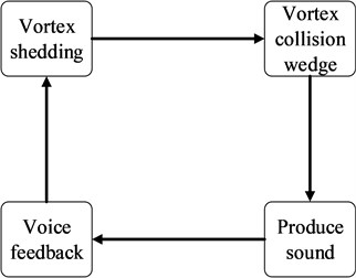
Fig. 3Schematic diagram of different resonator types
a) Helmholtz resonant cavity
b) Half-wavelength resonant cavity
c) Quarter-wave resonant cavity
d) Cone structure resonator
(2) Analysis of electromechanical conversion mechanism.
The conversion from vibration energy to electrical energy mainly includes: piezoelectric effect, electromagnetic induction, and friction power generation. The piezoelectric effect is that the collector uses the piezoelectric vibrator to convert the mechanical vibration into the alternating strain of the piezoelectric material, and generates voltage or current through the piezoelectric effect. Triboelectric power generation is a charge pump effect that relies on the potential of the friction point, and electricity is generated by the friction between a polyester fiber sheet and a polydimethylsiloxane sheet. The acoustic energy collector based on the piezoelectric effect of the cavity structure has become the main energy conversion method due to its simple structure, high power density and high output voltage. Compared with the piezoelectric effect, the magnetoelectric effect has the characteristics of high output current and low cost, but the structure is generally relatively complex, and it is also a popular energy conversion method for acoustic energy harvesters. Friction power generation can use environmental energy such as sound energy, water power, ocean waves, etc., and the manufacturing process is simple, but the power density is low. For the cavity-based acoustic energy harvesters,the vibration modeling of the diaphragm usually uses a lumped parameter model for parameter analysis. The model is generally equivalent to a mass spring damping system [17]. The specific formula is:
The four parameters on the left side of the equation represent mass, damping, spring, and electromechanical coupling force, and the right side of the equation represents acoustic excitation.
3. Acoustic energy collector based on cavity structure
The acoustic energy collector uses the cavity acoustic mode to capture the acoustic signal in a certain frequency range at the mouth of the cavity, achieves fluid-solid coupling and amplifies the acoustic vibration excitation, and then through piezoelectric, magnetoelectric and friction power generation mechanisms, the acoustic energy is finally converted into electrical energy. The following first analyzes the relevant theories of different transduction effects, and then analyzes some classic structures and cases.
3.1. Analysis of research status of flutter-type harvesting device
Piezoelectric energy conversion technology has the characteristics of high power density, large output voltage, and small size, which has become a mainstream research direction of acoustic energy harvesters [18], [19]. The cavity-based piezoelectric acoustic energy collectors can be divided into PVDF piezoelectric film and PZT piezoelectric vibrator according to the different piezoelectric materials [1], [20].
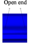
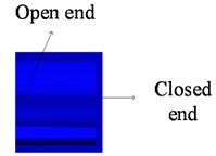
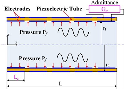
The acoustic energy collector using the PZT piezoelectric vibrator has a larger structure than the PVDF piezoelectric membrane structure, but the output power is higher. For example, Horowitz et al. designed a miniature acoustic energy harvester based on the calculation of the resonant frequency of the Helmholtz cavity by Alster M et al. [21], [22]. It uses PZT piezoelectric vibrator to generate electricity. The piezoelectric vibrator has a silicon substrate layer, a TiO2 layer and a PZT ring layer with top and bottom electrodes. The piezoelectric vibrator and two electrodes are mounted on an insulating silicon wafer and connected to a Helmholtz resonator. Finally, the device is packaged into a miniature acoustic energy collector chip. The experiment measured that when the incident sound pressure is 149 dB and the best load is 982.9 Ω, the maximum output power is 6 pW, the resonance frequency is 13.568 kHz, and the output power density is 0.34 μW/cm2. Therefore, the Helmholtz type acoustic energy harvester has a higher resonance frequency, but a lower output power density. Li et al. designed a PZT piezoelectric ceramic beam array energy harvester using a quarter-wavelength resonator [23]. However, in the case of a single piezoelectric beam without a quarter-wavelength resonator, the collected voltage and power are only 0.038 V and 0.313 μW, while a single piezoelectric beam placed near the opening of the quarter-wavelength resonator Beam, the output voltage is 1.51 V, and the output power is 0.498 mW. This result shows that the quarter-wavelength resonator can increase the output voltage and output power. Yang et al. developed a broadband acoustic energy collector [24], as shown in Fig. 4. The dual PZT piezoelectric beam is located on the top of the Helmholtz resonator instead of inside, and the dual PZT piezoelectric beam with neodymium magnets is placed in the middle of the top plate. When the maximum acceleration is applied, the matching of the resonance frequency of the Helmholtz resonator and the piezoelectric beam with magnet has a strong coupling effect. When the sound pressure of the collector is lower than 100 dB, the collected power is 0.137-1.43 mW at the resonance frequency of 170 k-206 Hz, which proves that increasing the bandwidth is beneficial to increase the output power. Izhar et al. designed a sound energy collector with three degrees of freedom [25]. The purpose of increasing the degrees of freedom is to expand the narrow frequency bandwidth. The experimental results show that the collector with the cantilever beam has three resonance peaks at 1501, 1766 and 1890 Hz, while the collector without cantilever beam has two formant peaks at 1501 and 1938 Hz. Obviously, the collector with cantilever beam has higher output voltage. In order to improve the energy harvesting efficiency of the 3-DOF acoustic energy harvester, Khan et al. changed the structure of the traditional circular Helmholtz resonant cavity from the design of the cavity structure, and designed a Helmholtz resonant cavity with a cone structure [26]. As shown in Fig. 5, the experimental results show that the tapered Helmholtz resonator can better amplify the sound pressure under the same conditions, the voltage obtained is increased by 33.33 %, and the output power is increased by 76.26 %. Yuan et al. studied the spiral structure from the perspective of cochlear bionics and designed a new type of acoustic energy harvester with spiral structure [27], as shown in Fig. 6. The design of helical tube is similar to the principle of quarter-wavelength tube, but the use of the helical structure makes the structure smaller, and the resonance frequency is not much different from that of the quarter-wavelength tube. The experimental results show that the resonant frequency of the device with the total length of 412 mm and the thickness of the tube wall of 2 mm is 193 Hz when the sound pressure is 100 dB, which is the same as the resonant frequency of the quarter wavelength resonator with the length of 444 mm. However, unlike the quarter wavelength tube, the spiral tube has low frequency characteristics. The curved neck inlet can reduce the acoustic resonance frequency, so the structure is suitable for small volume, low frequency acoustic energy acquisition. Li et al. designed a jet acoustic energy collector based on a quarter-wavelength tube [28], as shown in Fig. 7. The open end of the quarter-wavelength tube is designed as a wedge structure. The wedge structure can better cause the instability of the jet and produce a larger sound pressure amplitude. A PZT piezoelectric vibrator is installed at the closed end of the pipe. The radiated sound pressure causes the vibration of the piezoelectric vibrator to generate electricity. The research results show that when the jet flow rate is 100.85 m/s and the load resistance is 6 kΩ, the maximum output power is as high as 45.3 mW, which is suitable for fuze power supply.
Fig. 4Broadband acoustic energy collector
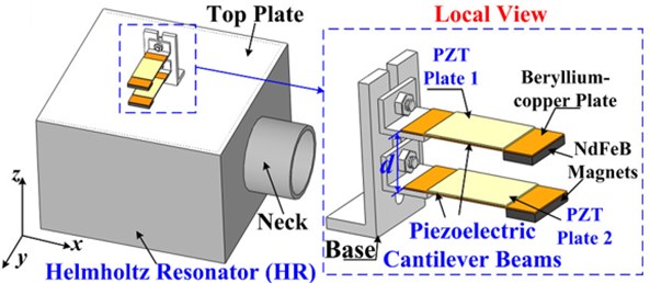
Fig. 5Conical cavity acoustic energy collector
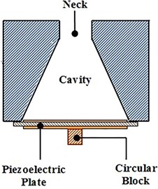
Fig. 6Spiral cavity acoustic energy collector
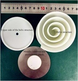
Fig. 7Jet acoustic energy collector
The acoustic energy collector based on PVDF piezoelectric film as piezoelectric material has the characteristics of small structure size and low resonance frequency. For example, Pillai et al. designed a sound energy collector with a tapered neck [29]. A flexible triangular sheet is provided in the collector, and the triangular sheet is connected with the free end of the flexible PVDF cantilever beam. When the triangular sheet is stressed, the cantilever beam is bent and twisted, and the flexible PVDF piezoelectric film is excited to generate electricity. The experiment found that the output voltage is 673 mV when the resonant frequency is 122 Hz and the sound pressure is 98 dB when the conical neck is used, and the output voltage is 468 mV when the resonant frequency is 125 Hz and the sound pressure is 98 dB when the cylindrical neck is used. Therefore, the tapered neck can increase the sound pressure magnification and help the sound energy collector output a higher voltage. They also verified whether the improvement of energy acquisition power was beneficial by increasing the mass of the triangular slice [30]. The results showed that after increasing the mass of the triangular slice, the output voltage was 842 mV when the resonant frequency was 99 Hz and the sound pressure was 103 dB, which proved that the mass of the triangular slice was conducive to the improvement of the output voltage. Li et al. used PVDF piezoelectric array to design a piezoelectric array acoustic energy collector [31], as shown in Fig. 8. The piezoelectric array is designed to be consistent with the cavity acoustic mode frequency, and the multiple piezoelectric beams are placed inside the cavity. The results show that the different placement of the piezoelectric beams will lead to different output powers. The zigzag placement of the piezoelectric beam is beneficial to increase the output power. When the sound pressure is 100 dB, the output voltage is 0.696 V and the output power is 0.31 μW. When the sound pressure is 110 dB, the output voltage is 1.48 V and the output power is 2.2 μW. Zhou et al. designed a flexible tube acoustic energy collector [32], as shown in Fig. 9. He directly used piezoelectric materials to design a quarter-wavelength tube, and made the flexible PVDF piezoelectric tube vibrate and generate electricity according to the radial radiation of sound pressure. During the vibration process, due to the different sound pressures in the piezoelectric tube, some parts of the piezoelectric tube are compressed and some parts are stretched. The stretched part and the compressed part are insulated from each other, thereby avoiding the cancellation of charges, and each output voltage independently. Biswal et al. designed a low-frequency sound energy collector with holes [33]. He improved the performance of the energy harvester of the cantilever structure by introducing through holes. In the experiment, the flexible PVDF was attached to the cantilever beam. When the acceleration is 3.7 g, the output power of the non-porous structure is 14.6 μW, and the output power of the porous structure is 59.93 μW. And it is found that the lower the resonance frequency of the vibration, the more obvious the output power is improved by the structure with holes.
Fig. 8Piezoelectric array acoustic energy collector
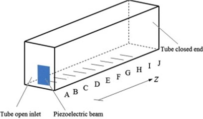
Fig. 9Flexible tube acoustic energy collector
3.2. Electromagnetic energy conversion technology of acoustic energy harvester
Magnetoelectric energy conversion technology is the relative movement of the magnet and the coil, which causes the change of the magnetic flux of the coil, and then generates the induced electromotive force. It has the characteristics of high output current and low cost, but the structure is generally more complicated than piezoelectric energy conversion. A typical electromagnetic acoustic energy collector has the same membrane as a piezoelectric acoustic energy collector [34]. The vibration of the membrane drives the magnet or coil to vibrate, causing changes in the magnetic flux in the closed coil, and then generating induced electromotive force, as shown in Fig. 10.
Fig. 10Typical electromagnetic acoustic energy collector
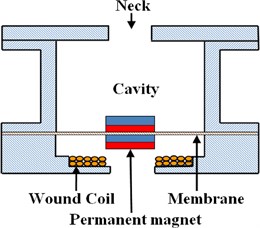
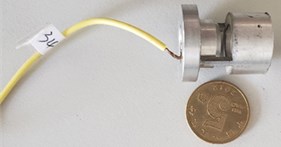
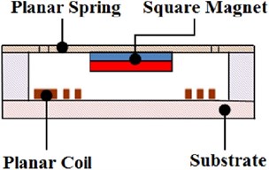
Compared with piezoelectric energy harvesting, the output current of magnetoelectric energy harvesting is larger, but the output voltage is generally lower, which is suitable for working conditions of high current and low voltage. The most representative one is the fuze jet generator designed by Harry Diamond et al. in 1960 [35], which has been successfully used as a fuze power source for M433, M443, M444 electronic time fuzes and multi-purpose rocket fuzes. The jet column electromagnetic energy collector designed by Wang et al. [36], as shown in Fig. 11, uses the periodic oscillation of the pressure inside the cavity when the fluid passes through the cavity to cause the permanent magnet to vibrate up and down to generate electricity. The experiment measured that when the load is 25 Ω, the cavity pressure oscillation amplitude is 254 Pa, and the vibration frequency is 30 Hz, the maximum output power is 0.4 μW. Based on the literature [25] [26], Izhar et al. developed an electromagnetic acoustic energy harvester with a cone-shaped Helmholtz cavity [37], as shown in Fig. 12. The collector has two winding coils, one is a cylindrical type surrounded by a magnet, and the other is a disc type under the magnet to maximize power output. The experimental results show that the collector can produce resonance phenomenon at 330.3 Hz and 1332 Hz, in which 330.3 Hz is the resonance between sound wave and membrane with magnet, and 1332 Hz is the resonance between sound wave and Helmholtz resonator, and the resonance frequency is 330.3 Hz, the sound pressure is 100 dB, the measured maximum output power is 212 μW. In order to improve the reliability of the structure, Khan et al. improved the literature [37], fixed the magnet, while the coil can move, designed a fixed magnet electromagnetic sound energy collector [38], and used a larger permanent magnet. The experimental results show that when the sound pressure is 100 dB and the best load is 50 Ω, the measured maximum output power is 789.65 μW. Lai et al. designed a miniature electromagnetic sound energy collector [39], as shown in Fig. 13. The energy conversion structure consists of a nickel planar coil and a neodymium magnet attached to a suspension plate. Through thermal evaporation, photolithography, electrodeposition and wet etching processes, a planar coil and a double-sided thermal oxide silicon wafer are fabricated on a 500 µm thick double-sided thermal oxide wafer suspension plat. The equipment size is only 3 mm×3 mm×1 mm. The experimental results show that when the distance between the loudspeaker and the miniature sound energy harvester is 5 mm, the system resonates, the resonance frequency is 470 Hz, and the output voltage is 0.24 mV.
Fig. 11Jet column type electromagnetic acoustic energy collector
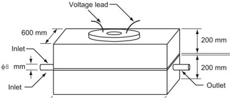
Fig. 12Conical cavity acoustic energy collector
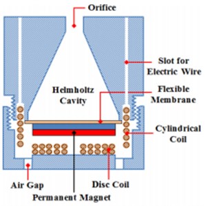
Fig. 13Miniature acoustic energy collector
3.3. Other energy exchange techniques for sound energy collectors
The research on other energy conversion technologies of acoustic energy harvesters mainly includes the use of friction nanometer power generation, acoustic crystal resonant cavity power generation, and hybrid energy conversion technology.
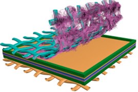
Triboelectric nanopower generation is two materials with different binding abilities to electrons. When they come into contact with each other, electrons are gained or lost, and current is generated in an external circuit, which converts mechanical energy into electrical energy. For example, Yang et al. first developed a triboelectric acoustic energy harvester using Helmholtz resonators [40], its power generation materials are made of polytetrafluoroethylene film and porous aluminum film electrodes. The experimental results show that at 70-110 dB, the maximum electric power density of the collector is 60.2 mW/m2, which can directly light up 17 light-emitting diodes. Moreover, it was found in the experiment that the collector can also be used as a self-powered acoustic sensor for sound source localization. Martin Olsen et al. developed a nano-friction piezoelectric generator [41]. A piezoelectric film is placed in the wind tunnel. Under the action of the wind, the piezoelectric film vibrates between the two copper electrodes. It is measured through experiments that the electric energy generated when the wind speed is 1.6 (m·s-1) is enough to light up an LED light, and found that as the wind speed increases from 0-8 (m·s-1), the vibration frequency also linearly increases. Cui et al. designed a mesh structure friction nano-acoustic energy collector [42], as shown in Fig. 14. It has two bases and a vibrating membrane. The upper substrate of stainless steel mesh and PVDF nanofiber is the upper electrode, and the lower substrate of aluminum mesh material is the lower electrode. The experimental results show that the mesh structure is conducive to air circulation and the propagation of sound waves. The incident sound waves make the vibrating membrane oscillate between the aluminum and PVDF nanofibers and repeat contact and separation to generate electric current. It is measured that the acoustic energy collector can work stably in a bandwidth of 50-425 Hz, the maximum charging rate is 61 μc/s, and the maximum power density is 202 mW/m3. Continuous working for 7 days, 100 million cycles of vibration, the power generation signal is not attenuated.
Fig. 14Nano energy harvesters with mesh structure friction
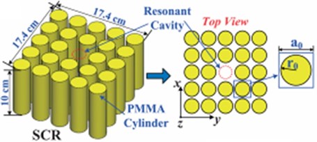
Acoustic crystal resonant power generation uses the point defect between the acoustic energy crystal and the piezoelectric material as a resonant cavity. Acoustic energy can enter the defect cavity of the acoustic crystal when incident, and the piezoelectric material completes electrical energy conversion in the acoustic crystal cavity. For example, Wu et al. used a polymethyl methacrylate cylinder to form a two-dimensional square acoustic wave crystal, and designed an acoustic crystal resonance energy harvester [43], in the 5×5 structure model, the sound pressure is increased by 4.94 times and the sound power is increased by 24.4 times compared with the resonant cavity without acoustic crystal. Yang et al. designed a coupled resonant acoustic energy harvester by simultaneously using an acoustic wave crystal with a resonant cavity and a Helmholtz resonator to expand the pressure, and designed a coupled resonant acoustic energy harvester [44], As shown in Fig. 15. The acoustic wave crystal resonator is composed of 5×5 polymethyl methacrylate cylinders. The central cylinder of the acoustic wave crystal is removed and embedded in the air background. The experimental results show that the acoustic crystal sound pressure gain at 5.535 kHz is 5.5, the Helmholtz resonator sound pressure gain is 5.0, and the coupled resonant structure has a sound pressure gain of 28.0 at 5.545 kHz. The results show that there is a strong acoustic resonance coupling between the sonic crystal resonator and the Helmholtz resonator, and when the sound pressure is 110 dB and the resonance frequency is 5.545 kHz, the maximum power collected is 429 μW and the peak voltage is 3.89 V.
Fig. 15Resonant energy collector of acoustic crystal
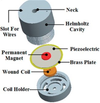
Hybrid energy conversion technology is to generate electric energy through the joint action of two or more energy conversion technologies. At present, the most common one is to combine piezoelectric energy conversion technology and magnetoelectric energy conversion technology. Hybrid energy conversion technology combines the characteristics of piezoelectric energy conversion technology with output voltage and magnetoelectric energy conversion technology with high output current, which is an important research direction for future research on energy harvesters. For example, Khan et al. designed a sound energy harvester using a hybrid energy conversion method [45], as shown in Fig. 16. The collector consists of a Helmholtz resonator, a piezoelectric plate with magnets and a wound circular coil. It uses both piezoelectric and electromagnetic energy conversion methods to collect as much sound energy as possible. In the piezoelectric transducer part, the sound pressure is 130 dB, the matching load is 1 kΩ, the resonance frequency is 2.1 kHz, the measured output voltage is 223 mV, and the maximum power is 50 μW. In the electromagnetic transducer part, the sound pressure is 130 dB, the matching load is 114 Ω, the resonance frequency is 2100 Hz, the measured output voltage is 38 mV, and the maximum power is 2.86 μW. Zhou et al. designed a bistable acoustic energy collector [46], it consists of a flat plate, a curved plate, a movable magnet and a piezoelectric beam with a fixed magnet. The fixed magnet and the movable magnet have the same polarity to apply repulsive force to maintain stability. The experimental results show that the system has two stable equilibrium positions, which can quickly maintain equilibrium between the equilibrium positions, thereby generating high output power. It can also optimize the separation distance according to the given sound pressure to make it resonate and generate the maximum output power. When the incident sound pressure is 105 dB and the separation distance is 17 mm, the maximum open circuit voltage measured is 0.4 V.
Fig. 16Hybrid acoustic energy collector
3.4. Performance analysis of various acoustic energy collectors
The structural characteristics and main parameters of the above different types of acoustic energy collectors are summarized with Table 1, and the current research status of piezoelectric acoustic energy collectors and magnetoelectric acoustic energy collectors are compared according to Table 1. Analyze the input and output performance of different types of acoustic energy harvesters through the comparison of output voltage, output power, power density, resonance frequency, and structure size. It is found that the resonance frequency of the electromagnetic sound energy harvester is much lower than the resonance frequency of the piezoelectric sound energy harvester, and the internal resistance of the piezoelectric sound energy harvester is much higher than the internal resistance of the piezoelectric sound energy harvester.
Table 1Structure and output parameters of sound energy collector
Species | Structure size (cm3) | Resonance frequency (Hz) | Internal resistance (Ω) | Output voltage (V) | Output Power (mW) | Power density (mW/m3) | |
Piezoelectric transducer | 2.445 | 13.57×10³ | 980 | 6×10⁻⁹ | 2.94×10⁻¹² | Horowitz [21] | |
840 | 200 | 19.37×10³ | 15.689 | 12.69 | 15.12×10⁻⁶ | Li [22], [23] | |
3972.22 | 201 | 38×103 | 1.43 | 0.36×10⁻⁶ | Yang [24] | ||
13.12 | 1501 | 4×10³ | 0.461 | 0.214 | 16.32×10⁻³ | Izhar [25] | |
251 | 175 | 11×103 | 7.3×10⁻³ | 29.1×10⁻⁶ | Yuan [27] | ||
1335 | 6.1×10³ | 3×10³ | 16.48 | 45.3 | 0.034 | Li [28] | |
2375.25 | 99 | 0.942 | Pillai [29] | ||||
1160 | 146 | 190×103 | 1.48 | 2.2×10⁻³ | 0.11×10⁻³ | Li [31] | |
1×10⁶ | 1×10⁻³ | Zhou [32] | |||||
23 | 1×10⁶ | 5.68 | 59.9×10⁻³ | Biswal [33] | |||
Magnetoelectric transducers | 324×103 | 30 | 25 | 10.2×10⁻³ | 0.4×10⁻³ | Wang [36] | |
330.3 | 140 | 0.11 | 212×10-3 | Izhar [37] | |||
13.57 | 319 | 50 | 0.198 | 0.789 | 58.19×10⁻⁹ | Khan [38] | |
9×10⁻³ | 470 | 0.24×10⁻³ | Lai [39] | ||||
Other transducers | 512 | 240 | 6×10⁶ | 30.8 | 60.2×10⁻⁶ | Yang [40] | |
175 | 100 | 90 | 202 | Cui [42] | |||
4.6 | 5545 | 4400 | 3.89 | 0.429 | 93×10-9 | Yang [44] | |
2100 | 1000 | 0.223 | 5×10⁻³ | Khan [45] | |||
2000 | 0.4 | Zhou [46] |
Summarize and compare Table 1 and analyze the output characteristics of piezoelectric and magneto-electric acoustic energy collectors, such as structure size, output voltage, output current and other parameters, as shown in Table 2.
Table 2Comparison of piezoelectric and magnetoelectric energy harvesters
Species | Internal resistance | Output current | Output voltage | Resonance frequency | Structure size | Processing technology | Working sound pressure |
Piezoelectric energy harvester | High | Low | High | High | Small | Simple | High |
Magnetoelectric energy harvester | Low | High | Low | Low | Big | Complex | Low |
4. Conclusions
The collection of environmental energy has received more and more attention, and sound energy is the most extensive energy in the environment. The collection technology and application research of sound energy have become a research hotspot at present. The design of the cavity structure is particularly critical in acoustic energy collection. The Helmholtz resonant cavity is the most widely used cavity structure. In order to obtain greater sound pressure amplification, the improvement of Helmholtz resonator is also a new research focus. The quarter-wavelength resonant cavity is conducive to the miniaturization of the structure design, the geometric structure of the resonant cavity is optimized, and the design of the coupling model is conducive to improving the sound pressure amplification. The electromechanical energy conversion method of the acoustic energy harvester is mainly piezoelectric, supplemented by magnetoelectric type. With the emergence of new technologies and new materials, friction power generation and acoustic crystal resonance power generation have become a new research direction. Hybrid power generation can make full use of the advantages of piezoelectric and magnetoelectric power generation. It can meet the output conditions of high voltage and high current. It has the widest application range. It is the future development trend of acoustic energy harvesters. However, the miniaturization of the structure is a difficult point.
References
-
A. Abdelkefi, “Aeroelastic energy harvesting: A review,” International Journal of Engineering Science, Vol. 100, pp. 112–135, Mar. 2016, https://doi.org/10.1016/j.ijengsci.2015.10.006
-
L. Shaw, R. Clark, and D. Talmadge, “F-111 generic weapons bay acoustic environment,” Journal of Aircraft, Vol. 25, No. 2, pp. 147–153, Feb. 1988, https://doi.org/10.2514/3.45555
-
X. S. Wang, D. G. Yang, J. Liu, Zhou, and A. Shi, “Research progress on noise caused by compressible cavity flow,” (in Chinese), Experimental Fluid Mechanics, Vol. 32, No. 3, pp. 1–16, 2018, https://doi.org/10.11729/syltlx20170132
-
V. Sarohia, “Experimental investigation of oscillations in flows over shallow cavities,” AIAA Journal, Vol. 15, No. 7, pp. 984–991, Jul. 1977, https://doi.org/10.2514/3.60739
-
Z. P. Li and H. J. Chen, “Piezoelectric energy harvesting technology based on wind-induced vibration effects,” (in Chinese), Science Technology and Engineering, Vol. 21, No. 6, pp. 2132–2140, 2021.
-
S. P. Beeby and T. O’Donnell, Energy Harvesting Technologies. Springer, 2009.
-
Z. Q. Ding, R. W. Chen, and P. Y. Zhang, “Design and optimization of spherical permanent magnet array vibration energy harvester,” (in Chinese), Vibration and Shock, Vol. 35, No. 2, 2016, https://doi.org/10.13465/j.cnki.jvs.2016.02.036
-
C. W. Rowley and D. R. Williams, “Dynamics and control of High-Reynolds-number flow over open cavities,” Annual Review of Fluid Mechanics, Vol. 38, No. 1, pp. 251–276, Jan. 2006, https://doi.org/10.1146/annurev.fluid.38.050304.092057
-
C. J. Campagnuolo, “Fluidic Generator to Power Rocket Proximity Fuze AD-A131062,” Washington, Government Technology Report, 1983.
-
R. Goodyear, “Performance of the Fluidic Power Supply for the XM445 Fuzein Supersonic Wind Tunnels AD2A097625,” Washington, Government Technology Report, 1981.
-
J. F. Forrest and J. Wheaton, “A Low-Cost Fluidic-ElectronicTime Fuze AD2A 014943,” Washington, Government Technology Report, 1975.
-
Xiaofeng Sun and Sheng Zhou, Aeroacoustics, (in Chinese). Beijing: National Defense Industry Press, 1994.
-
M. J. Lighthill, “On sound generated aerodynamically I. General theory,” Proceedings of the Royal Society of London. Series A. Mathematical and Physical Sciences, Vol. 211, No. 1107, pp. 564–587, Mar. 1952, https://doi.org/10.1098/rspa.1952.0060
-
M. J. Lighthill, “On sound generated aerodynamically II. Turbulence as a source of sound,” Proceedings of the Royal Society of London. Series A. Mathematical and Physical Sciences, Vol. 222, No. 1148, pp. 1–32, Feb. 1954, https://doi.org/10.1098/rspa.1954.0049
-
M. A. Pyrkosz and C. V. Karsen, Coupled Vibro-Acoustic Model of the Titian Stradivari Violin. Springer International Publishing, 2014.
-
H. Kang and M. Tsutahara, “An application of the finite difference-based lattice Boltzmann model to simulating flow-induced noise,” International Journal for Numerical Methods in Fluids, Vol. 53, No. 4, pp. 629–650, Feb. 2007, https://doi.org/10.1002/fld.1299
-
Yang Lei, Xue Zhicheng, He Xingyue, Gu Xinfeng, and Wang Debo, “Research review of acoustic energy harvesters,” (in Chinese), Microelectronics, Vol. 50, No. 1, pp. 112–117, 1977.
-
S. Roundy and P. K. Wright, “A piezoelectric vibration based generator for wireless electronics,” Smart Materials and Structures, Vol. 13, No. 5, pp. 1131–1142, Oct. 2004, https://doi.org/10.1088/0964-1726/13/5/018
-
S. Roundy, P. K. Wright, and J. Rabaey, “A study of low level vibrations as a power source for wireless sensor nodes,” Computer Communications, Vol. 26, No. 11, pp. 1131–1144, Jul. 2003, https://doi.org/10.1016/s0140-3664(02)00248-7
-
Lin Dakai, Acoustic Control of Turbulent Jets. Beijing: Aviation Industry Press, 2018.
-
M. Alster, “Improved calculation of resonant frequencies of Helmholtz resonators,” Journal of Sound and Vibration, Vol. 24, No. 1, pp. 63–85, Sep. 1972, https://doi.org/10.1016/0022-460x(72)90123-x
-
S. B. Horowitz, M. Sheplak, L. N. Cattafesta, and T. Nishida, “A MEMS acoustic energy harvester,” Journal of Micromechanics and Microengineering, Vol. 16, No. 9, pp. S174–S181, Sep. 2006, https://doi.org/10.1088/0960-1317/16/9/s02
-
B. Li, J. H. You, and Y.-J. Kim, “Low frequency acoustic energy harvesting using PZT piezoelectric plates in a straight tube resonator,” Smart Materials and Structures, Vol. 22, No. 5, p. 055013, May 2013, https://doi.org/10.1088/0964-1726/22/5/055013
-
A. Yang et al., “Note: High-efficiency broadband acoustic energy harvesting using Helmholtz resonator and dual piezoelectric cantilever beams,” Review of Scientific Instruments, Vol. 85, No. 6, p. 066103, Jun. 2014, https://doi.org/10.1063/1.4882316
-
Izhar and F. U. Khan, “Three degree of freedom acoustic energy harvester using improved Helmholtz resonator,” International Journal of Precision Engineering and Manufacturing, Vol. 19, No. 1, pp. 143–154, Jan. 2018, https://doi.org/10.1007/s12541-018-0017-z
-
Izhar and F. U. Khan, “An improved design of Helmholtz resonator for acoustic energy harvesting devices,” in 2016 International Conference on Intelligent Systems Engineering (ICISE), Jan. 2016, https://doi.org/10.1109/intelse.2016.7475135
-
M. Yuan, Z. Cao, J. Luo, and Z. Pang, “Helix structure for low frequency acoustic energy harvesting,” Review of Scientific Instruments, Vol. 89, No. 5, p. 055002, May 2018, https://doi.org/10.1063/1.5021526
-
Z. Li, J. Li, and H. Chen, “Experimental research on excitation condition and performance of airflow-induced acoustic piezoelectric generator,” Micromachines, Vol. 11, No. 10, p. 913, Sep. 2020, https://doi.org/10.3390/mi11100913
-
M. A. Pillai and D. Ezhilarasi, “Improved acoustic energy harvester using tapered neck Helmholtz resonator and piezoelectric cantilever undergoing concurrent bending and twisting,” Procedia Engineering, Vol. 144, pp. 674–681, 2016, https://doi.org/10.1016/j.proeng.2016.05.065
-
S. K. Tang, “On Helmholtz resonators with tapered necks,” Journal of Sound and Vibration, Vol. 279, No. 3-5, pp. 1085–1096, Jan. 2005, https://doi.org/10.1016/j.jsv.2003.11.032
-
B. Li, A. J. Laviage, J. H. You, and Y.-J. Kim, “Harvesting low-frequency acoustic energy using quarter-wavelength straight-tube acoustic resonator,” Applied Acoustics, Vol. 74, No. 11, pp. 1271–1278, Nov. 2013, https://doi.org/10.1016/j.apacoust.2013.04.015
-
M. Zhou, Y. Fu, B. Wang, and M. S. H. Al-Furjan, “Vibration analysis of a longitudinal polarized piezoelectric tubular energy harvester,” Applied Acoustics, Vol. 146, pp. 118–133, Mar. 2019, https://doi.org/10.1016/j.apacoust.2018.11.016
-
P. Biswal, S. K. Kar, and B. Mukherjee, “Performance improvement of low frequency piezoelectric energy harvester incorporating holes with an in-house experimental set-up,” Meccanica, Vol. 56, No. 1, pp. 59–72, Jan. 2021, https://doi.org/10.1007/s11012-020-01279-y
-
F. U. Khan and Izhar, “Electromagnetic-based acoustic energy harvester,” in 2013 16th International Multi Topic Conference (INMIC), pp. 125–130, Dec. 2013, https://doi.org/10.1109/inmic.2013.6731337
-
C. J. Campagnuolo, “Fluidic Generator to Power Rocket Proximity Fuze,” ADA131062, 1983.
-
F. U. Khan and Izhar, “Electromagnetic-based acoustic energy harvester,” in 2013 16th International Multi Topic Conference (INMIC), Vol. 41, pp. 356–364, Dec. 2013, https://doi.org/10.1109/inmic.2013.6731337
-
Izhar and F. U. Khan, “Electromagnetic based acoustic energy harvester for low power wireless autonomous sensor applications,” Sensor Review, Vol. 38, No. 3, pp. 298–310, Jun. 2018, https://doi.org/10.1108/sr-04-2017-0062
-
F. U. Khan and Izhar, “Electromagnetic energy harvester for harvesting acoustic energy,” Sādhanā, Vol. 41, No. 4, pp. 397–405, Apr. 2016, https://doi.org/10.1007/s12046-016-0476-9
-
Tenghsien Lai, Changhan Huang, and Chingfu Tsou, “Design and fabrication of acoustic wave actuated microgenerator for portable electronic devices,” in 2008 Symposium on Design, Test, Integration and Packaging of MEMS/MOEMS (MEMS/MOEMS), Vol. 9, No. 11, p. 2008, Apr. 2008, https://doi.org/10.1109/dtip.2008.4752946
-
J. Yang, J. Chen, Y. Liu, W. Yang, Y. Su, and Z. L. Wang, “Triboelectrification-based organic film nanogenerator for acoustic energy harvesting and self-powered active acoustic sensing,” ACS Nano, Vol. 8, No. 3, pp. 2649–2657, Mar. 2014, https://doi.org/10.1021/nn4063616
-
C. H. Yang et al., “A high efficient piezoelectric windmill using magnetic force for low wind speed in wireless sensor networks,” Journal of the Korean Physical Society, Vol. 73, No. 12, pp. 1889–1894, Dec. 2018, https://doi.org/10.3938/jkps.73.1889
-
N. Cui et al., “High performance sound driven triboelectric nanogenerator for harvesting noise energy,” Nano Energy, Vol. 15, pp. 321–328, Jul. 2015, https://doi.org/10.1016/j.nanoen.2015.04.008
-
L.-Y. Wu, L.-W. Chen, and C.-M. Liu, “Acoustic energy harvesting using resonant cavity of a sonic crystal,” Applied Physics Letters, Vol. 95, No. 1, p. 013506, Jul. 2009, https://doi.org/10.1063/1.3176019
-
A. Yang et al., “Enhanced acoustic energy harvesting using coupled resonance structure of sonic crystal and Helmholtz resonator,” Applied Physics Express, Vol. 6, No. 12, p. 127101, Dec. 2013, https://doi.org/10.7567/apex.6.127101
-
F. U. Khan and Izhar, “Hybrid acoustic energy harvesting using combined electromagnetic and piezoelectric conversion,” Review of Scientific Instruments, Vol. 87, No. 2, p. 025003, Feb. 2016, https://doi.org/10.1063/1.4941840
-
Z. Zhou, W. Qin, and P. Zhu, “Harvesting acoustic energy by coherence resonance of a bi-stable piezoelectric harvester,” Energy, Vol. 126, pp. 527–534, May 2017, https://doi.org/10.1016/j.energy.2017.03.062
Cited by
About this article

The research is financially supported by the Jiangsu College “Qing Lan Project” of China the Jiangsu College Natural Science Foundation of China, the Changzhou Applied Basic Research Plan of China (CJ20200010), and Postgraduate Research & Practice Innovation Program of Jiangsu Province (KYCX21-0263).
