Abstract
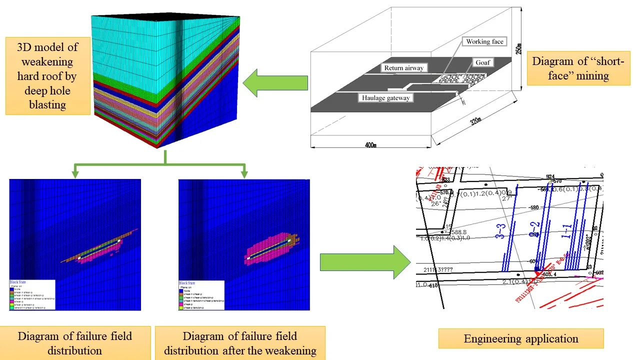
Based on the 211113 “short face” of Xinji No. 2 Mine of China Coal Group, this study investigated the weakening regularity of blasting vibration and rock bursting of roof through FLAC3D numerical simulation on the basis of the hard roof fracture regularity through theoretical analysis. The results show that the vibration frequency of the hard roof increases linearly with the increase of the distance from the source, and the vibration amplitude decreases exponentially with the increase of the distance from the source within 20 m from the blasting relief hole. Based on the above results, from the three indexes of controlling the amplitude, frequency and duration of pressure relief blasting vibration, it is proposed that the roof on the 211113 “short face” needs to be controlled by the advanced overlying strata weakening technology, and the parameters of advanced deep hole pre-splitting blasting are optimized. After the roof was weakened by the advanced deep-hole pre-splitting blasting, it can basically fall with mining. The blasting method can effectively avoid the phenomenon of large-area “hanging arch” and effectively prevent the occurrence of rock burst.
Highlights
- The finite element model for weakening hard roof by deep-hole pre-splitting blasting is established.
- Through the simulation of blasting weakening, principal stress distribution and failure field characteristics of surrounding rock are compared.
- The validity of finite element model for weakening hard roof is verified by engineering application.
1. Introduction
Huainan coalfield is one of the most representative coalfields in central China [1]. Its minable coal seams are usually covered by hard and thick rock strata with high strength, while it is often hard for extra thick and hard roof to fall with mining in coal seam mining process [2]. Large overhanging beams tend to be formed in hard rock strata after mining, resulting in “the large-area hanging arch” on the working face [3]. In turn, the stress concentrates in the disturbed zone, and the mine disasters such as the working face pressure frame and rock burst are caused. Besides, it may also cause deformation and damage to the roadway, which seriously affects the mining operation of the working face and the safety of workers [4-6]. In order to improve the resource recovery rate, working faces are often laid out in inconsistent lengths, that is, there are both conventional working faces with lengths of about 200 m and ultra-short working faces with lengths of tens of meters. A lot of researches have been carried out on the characteristics of the migration of overlying strata in the process of conventional mining face mining. Based on the specific filed projects, Lü [7], Wang [8], Wang [9] and other experts and scholars analyzed the distribution patterns of extra thick and hard roof fissures after mining on the fully mechanized top-coal mining face and proposed related roof management technology and control methods. Zhu et al. [10] used the rock mass fracture process analysis (RFPA2D) system to simulate the dynamic variation of the caving and supporting pressure of shallow-buried thick hard roof. With the development of numerical simulation software, great progress has been made in the numerical simulation technology of borehole blasting pressure relief. Xia et al. [11] used the method of reducing rock mechanics parameters in the blasting fissure range, and used FLAC3D software to simulate static equivalent pressure relief effect of borehole blasting in mining roadway, but static calculation neglected explosive explosion and its impact, rock breaking and vibration process, so the reliability of simulation results was low. Miao [12] used semi-empirical and semi-theoretical load wave and FLAC3D software to dynamically simulate the pressure relief effect of borehole blasting in coal mining face under different construction conditions. Although this method takes into account the dynamic effect of rock mass explosion and improves the reliability of numerical simulation, the applicability and precision of load wave should be determined by experiments, empirical formulas or engineering experience. The accuracy is still low. Qian et al. [13, 14] extracts the blasting load around the crushing zone calculated by ANSYS/LS-DYNA, and simulates the pressure relief effect of borehole blasting in hard rock roadway by using FLAC3D dynamic calculation module. The blasting load calculated by this method improves the shortage of experience and has more reliable theoretical basis, and is a more effective dynamic numerical simulation method for pressure relief of borehole blasting.
The above-mentioned traditional theories of mining pressure focused on the characteristics of rock mass migration in the basic top section of conventional-length working face mining. However, in the process of ultra-short working face mining, the stress field environment of overlying strata, the mechanical characteristics and failure mode of coal and rock mass differ obviously from that on the conventional working face. Therefore, due to the wide range of overlying strata fracture, It is necessary to further study the weakening law of vibration and impact rock breaking during the process of pressure relief by borehole blasting of “short face” huge thick and hard roof, as well as the effect and influence on coal and rock mass damage and stope rock pressure. In this way, a reasonable overlying strata step of ultra-short-face mining and roof management technology can be determined to ensure the safe and efficient recovery of ultra-short working face.
In this paper, taking the 211113 working face of Xinji No. 2 mine of China Coal Group as the research background, the study investigated the roof rupture regularity through the theoretical analysis and the FLAC3D numerical simulation method, and for the “short-face” hard roof, Besides, it carried out field tests of roof weakening by advanced deep-hole blasting to verify the rationality and practicability of the method in solving the problem of “short-face” hard roof.
2. Geological situation of construction
The 211113 working face is located in the west wing of the second-level central mining area of Xinji No. 2 mine. It starts from the middle truck yard and cross cut in the shared uphill tacks of #11 coal and #13 coal in the east. It is 107 m west of the 03 exploration line in the west, 7.8-27.6 m away from the 111111 goaf (finishing mining in Nov., 2003) in the south, near the contour line of #-640 coal-floor of #11-2 coal in the north. Its northern part belongs to the unutilized area of #11-2 coal. Vertically, it is 43.8-75.5 m from #13-1 coal seam, with an average of 63.9 m, and 5.1-27.2 m from #11-1 coal, with an average of 15.0 m. The minable length of air lane is about 599.4 m; the minable length of machine lane is about 582.1 m; the inclination length of the working face is about 98.6 m; and the minable area is about 124,670 m2. The method of long wall retreating comprehensive mechanized coal mining is adopted in the working face. The roof is managed by the method of full-caving mining, with the mining height designed to be 3.8 m. The physical and mechanical parameters of roof strata are listed in Table 1.
The mining seam is #11-2 coal with an inclination of about 35° and an average thickness of 3.6 m. There is a layer of black mud-stone with an average thickness of about 0.4 m in the coal seam. The structure of the coal seam is complex and the coefficient of variation of coal thickness is 18.0 %. With a recoverability index of 1, the coal seam belongs to a stable coal seam.
Table 1Physical and mechanical parameters of roof strata of 211113 working face
Layer number | Lithology | Layer thickness | Bulk density | Elastic modulus / MPa | Tensile strength / MPa | × |
1 | Quartz sandstone | 7 | 27 | 39400 | 7.5 | 275800 |
2 | Medium grain sandstone | 11 | 27 | 37400 | 7 | 411400 |
3 | Sandy mudstone | 7 | 25 | 7000 | 2.5 | 49000 |
4 | Fine grain sandstone | 15 | 27 | 35700 | 6 | 535500 |
5 | Coal seam | 0.5 | 15 | 7000 | 0.73 | 3500 |
6 | Siltstone | 7 | 25 | 35000 | 5.4 | 245000 |
7 | Fine sandstone | 4 | 27 | 35700 | 6 | 142800 |
3. Theoretical analysis of roof rock falling
3.1. Ultimate falling distance
The first weighting span of the hard roof, the thickness of a fall and the length of the working face are set as , , and 1, respectively, then /l. According to the prediction and estimation of relevant scholars [15, 16] on the working face of most hard roofs, for the hard roof, the length of general working face is greater than twice the first weighting. That is, the rock beam model can be used for estimation when ≤ 0.5, while the rock plate model is used when > 0.5. Therefore, the simplified fixed beam model can be used for analysis. However, for the double-pivot mechanical model, the rock beam just undergoes small deformation before it fractures due to the wide load distribution and low stress concentration of rock beam. Thus, the uniform load can be used to meet the requirements for calculation.
According to the rapid judgment method of key stratum [17], the value of × in Table 1 can be obtained: The hard rock sandstone stratum in the second layer is the key stratum, and the load formed by the effect of the second layer on the first layer is:
Therefore, the load of the hard top beam is 233.76 MPa and the sandstone 17 m on the immediate roof is the key stratum.
is set as the allowable tensile stress of the rock beam. When, normal stress of the rock stratum will reach the ultimate tensile strength, which will cause tensile fracturing of the rock stratum. The ultimate span formula for calculating the fracture of the beam is as follows:
Substituting 233.76 MPa, 7 MPa and 17 m into Eq. (2), it can be obtained that the ultimate falling distance for #11-2 coal is 132.11 m.
3.2. Determination of reasonable length of the hanging arch
Between the hard roof that falls for the first time and the overhanging beam that has not fall, the broken gangue at the roof fracture will support the rock beam to a certain extent, and the extended rock beam can be regarded as the overhanging beam. Therefore, the model is built, as shown in Fig. 1.
Fig. 1Mechanical model diagram of periodic weighting of hard rock beams
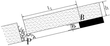
a) The model of overhanging beam
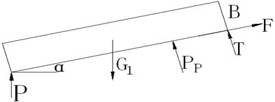
b) Force analysis of overhanging beam
According to Fig. 1(b), the equilibrium formula can be obtained as follows:
If the rock beam breaks from B, then and 7 MPa. In Eq. (3):
where is the gravity of the rock beam, ; and is the step of periodic weighting, 22 m.
Eq. (7) can be obtained by substituting Eqs. (4)-(6) into Eq. (3):
At the moment of rock beam breaking, can be represented as, where is the friction coefficient, 0.35-0.45. By combining the two equations, it can be concluded that when the force of the bracket reaches the rated resistance, , the maximum overhanging arch span is:
According to the type and parameters of working face, 30°, 4.6 m and 0.35, the maximum overhanging arch span of periodic weighting is estimated to be 25 m based on Eq. (8). Hence, the overhanging arch span of periodic weighting is controlled to 25 m, and the roof caving step is about 25 m in the early stage of mining.
According to theoretical calculation, a thick and hard roof with a face length of 65 m has a ultimate falling step of 132 m. The numerical simulation indicates that the nephogram of surrounding rock displacement and failure field at 90 m of “short-face” mining does not exhibit obvious characteristics of fracturing and falling, while the reasonable overhanging arch length is about 25 m under periodic weighting of 30° hard roof. In order to ensure the initial weighting, forced caving must be carried out to relieve the pressure of the roof.
4. Numerical simulation of stratum pressure behavior law during initial mining
4.1. Numerical simulation software
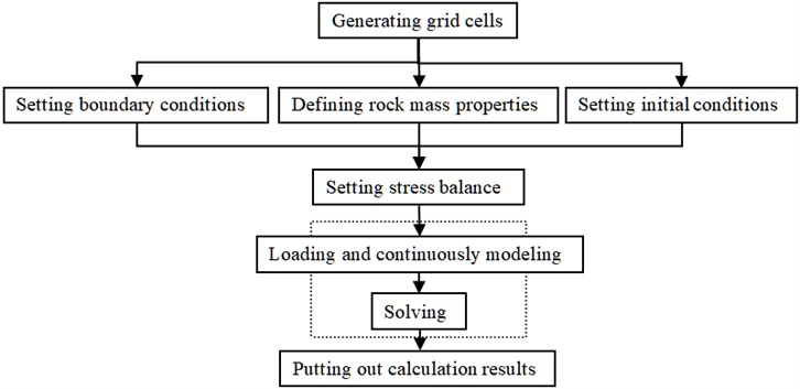
Numerical simulation is a simulation operation method and a practical technology for making analysis by computer simulation software. For mining engineering, the computer three-dimensional finite difference software FLAC3D plays an important role in the simulation application of underground engineering mining. Using the FLAC3D numerical simulation software to study the failure characteristics of excavated rock mass in underground engineering is an effective means to solve the problem of fracture mechanics of complex rock mass micro-structure. Since coal seam mining is a nonlinear mechanical evolution process of continuous mining and progressive failure in the complex layered tectonic rock mass, it is difficult to construct an appropriate complete mechanical solution model. The whole process of surrounding rock failure of the stope can be tracked in real time only by means of the computer dynamic operating system of numerical analysis software. In this way, the characteristics of space-time evolution of the stress field and displacement field of the rock mass can be obtained. Fig. 2 shows the framework of FLAC3D calculation.
Fig. 2Framework of FLAC3D calculation
4.2. Modeling
This simulation test is based on the engineering geology and mining technical conditions of the 211113 fully mechanized working face of Xinji Coal Mine. The three-dimensional calculation model of the effect of the working face mining on the overlying strata is established to carry out numerical simulation. The model dimensions are: 400 m of strike length, 320 m of slope length and 250 m of height, as presented in Fig. 3. The model, which takes 30° as the average angle of the coal seam and 3.8 m as mining height, contains the simulated #11 coal and its top and bottom rock strata. In the tilt direction of the model, emphasis is laid on the study of the effect of mining on the overlying strata in 211113 working face. At the same time, the boundary displacement is set in the simulation calculation process. The vertical displacement on the bottom of the model and the horizontal displacement on the sides of the model are restricted, and a corresponding vertical load is applied to the top of the model to simulate the weight of overlying strata. The specific model is illustrated in Figs. 3 and 4. The 211113 initial mining face is a knife-handle-shaped face with a length of 65 m. A large mining face whose face length is about 105 m is formed after the upper and lower working faces are connected. Therefore, it is necessary that the lower working faces is simulated.
Fig. 3Simulation of model geometry
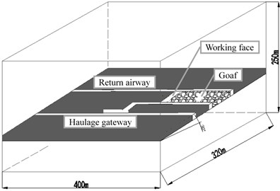
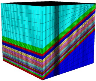
Fig. 43D calculation model grid of stope
4.3. Simulation results analysis
4.3.1. Analysis of mechanical failure characteristics of “short-face” surrounding rock
Through numerical calculation of 3D calculation model grid of stope, the distribution characteristics of principal stress and vertical displacement field in the inclined direction of the working face can be obtained at 20 m of initial mining, as shown in Fig. 5 and 6.
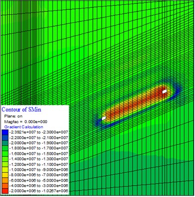
Fig. 5 is the cloud map of principal stress distribution at 20 m of initial mining. It can be seen that when the initial mining face advances for 20 m, the peak stress of the surrounding rock mainly exists in the overlying direct roof. As the working face advances, a stress concentration area is gradually formed in the roof and floor, and the areas gradually connect to form a whole. Under this circumstance, if the roof of the stope fail to fall in time, frame-pressing accidents are likely to take place.
Fig. 6 is the cloud map of vertical displacement field distribution at 20 m of initial mining. It can be observed that with the advancement of the working face, the roof subsidence of the goaf increases gradually, but it still maintains a relatively small value without fracturing or falling. Meanwhile, the upward displacement of the floor is increasing. According to this, it can be analyzed that since the roof of the stope is an extra hard and thick quartz sandstone, it is difficult to actively fall with the advancement of the working face in the natural state, which explains the small amount of the roof subsidence. The vertical stress increases continuously and transfers to the floor, producing a horizontal pressing force. Thereby, the upward displacement of the floor increases.
Through numerical calculation, the working face is advanced to 90 m. After that, the deformation and failure characteristics of surrounding rock in the inclined direction of working face can be obtained when the initial mining is 20 m and 90 m, respectively, as shown in Fig. 7.
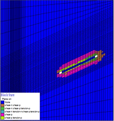
Fig. 7 is the diagram of failure field distribution of surrounding rock in the inclined direction of the “Short-face”. It shows deformation and failure characteristics of the surrounding rock in the mining face at different distances. As can be found in Fig. 7, with the increase of advancing distance, the failure degree of surrounding rock rises. However, what increases is mainly the floor failure depth rather than roof failure depth, mainly because the working face is extra hard and thick quartz sandstone and the length of the working face is too short to achieve effective deformation, fracturing or falling of the roof.
In summary, due to the short length of the 211113 “short face” and the extra hard and thick quartz sandstone in the overlying roof, with the advancement of the working face, the principal area of stress concentration is mainly located at the hard roof with very limited roof subsidence and failure scope. On this basis, the corresponding measures must be taken to weaken the roof in advance, so as to guarantee the falling of the roof as the work face recovers.
Fig. 5Cloud map of principal stress distribution at 20 m of initial mining
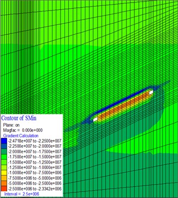
Fig. 6Cloud map of vertical displacement field distribution at 20 m of initial mining
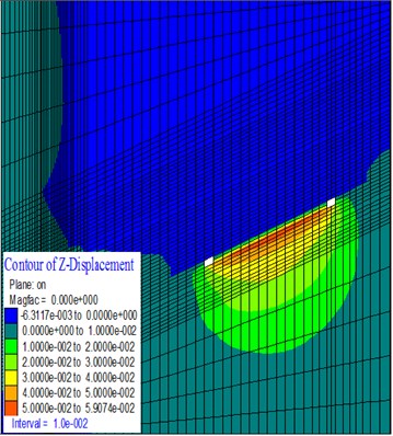
Fig. 7Diagram of failure field distribution of surrounding rock in the inclined direction of the “Short-face”
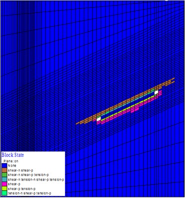
a) 20 m at the initial mining
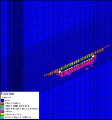
b) 90 m at the initial mining
4.3.2. Analysis of mechanical failure characteristics of surrounding rock after the advanced weakening “short-face” overlying strata
The measure of advanced weakening roof is considered. On the basis of the original model, the lithology of rock strata within a certain range of the #10 coal roof (to the vicinity of 17 meter thick overlying hard roof) is weakened in advance.
Using FLAC 3D to simulate explosive explosion, the explosion calculation model is shown in Fig. 1. The borehole diameter is 100 m and the borehole depth is 2 m. Blasting explosive is 2 # rock emulsified explosive. The explosive model is MAT_HIGH_EXPLOSIVE_BURN, the equation of state is Jones Wilkins-Lee (JWL), and the surrounding rock model is MAT_PLASTIC_KINEMATIC. The physical and mechanical parameters of surrounding rock are shown in Table 1, the parameters of explosive and equation of state are shown in Table 2, and the critical damping ratio is 0.5 %.
Table 2Parameters of explosives and state equations
Parameter | Density / (kg.m-3) | Explosion velocity / (m.s-1) | Detonation pressure / GPa | / GPa | / m3 | |
Numerical value | 1240 | 3200 | 3.174 | 4. 192 | 1.0 | 0. 15 |
After the weakening of the roof, the stress is re-balanced and the mining calculation is carried out once more. When the working face is advanced to 30 m, the principal stress characteristics of the surrounding rock in the inclined direction of the working face are compared and analyzed when the working face is 20 m, as shown in Fig. 8.
Fig. 8 is the cloud map of principal stress distribution for recovery at different distances after the weakening of “Short-face” overlying strata. After the advanced weakening roof technology is adopted to effectively weaken the “short-face” overlying strata, the principle stress distribution of surrounding rock in the stope has been greatly improved, and the overlying strata fall in time with the mining of the working face. Besides, the area of stress concentration extends outward and the degree of stress concentration is also significantly reduced. Meanwhile, it can be clearly seen from Fig. 8 that the overlying strata experience extensive roof falling and pressure relief in the range of 20-30 m in the working face. The fallen gangue fills the goaf in time, which prevents the appearance of “large-area overhanging arch”.
Fig. 8Cloud map of principal stress distribution for recovery at different distances after the weakening of “Short-face” overlying strata
a) 20 m of recovery
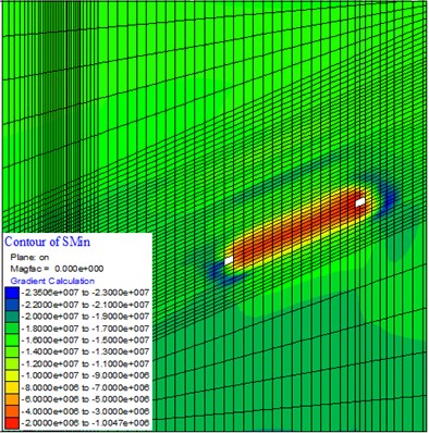
b) 30 m of recovery
Similarly, through numerical calculation, when the working face is advanced to 20 m and 30 m, the deformation and failure characteristics of the surrounding rock in the inclined direction of the working face can be obtained effectively, as shown in Fig. 9. It can be observed from Fig. 9 that after the effective weakening of the “short-face” overlying strata, the area of overlying stratum falling increases obviously with the recovery of the working face. The comparison between cloud maps of failure fields for 20 m and 30 m of recovery after the weakening of overlying strata suggests that when the working face is advanced to 30 m, the rock at the higher part of the overlying strata to fall from a height of about 24 m, and the overlying hard quartz sandstone in the stope start to fall. This indicates that due to the application of the advanced weakening roof technology, the distance for the first falling of “short-face” recovery becomes about 30 m, and the overlying strata fall off with mining.
Fig. 9Diagram of failure field distribution of surrounding rock for recovery at different distances after the weakening of “Short-face” overlying strata
a) 20 m of recovery
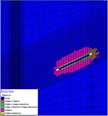
b) 30 m of recovery
5. The method of controlling hard roof with large inclined angles and its application
After the 211113 working face is recovered, the situation where the overhanging area of hard roof is too large appears. It is necessary to weaken the area. At present, the methods of hard roof weakening include the blasting method [18-20], the water injection method [21, 22], the joint weakening method [23-25], etc. According to the specific conditions of 211113 fully mechanized working face, the advanced deep-hole loose blasting method is adopted based on comprehensive consideration. An artificial fracture zone is made on the coal seam sandstone roof at a certain distance in front of the mining face. In this way, the roof falls in accordance with the expected target, thus decreasing the overhanging area of the goaf and the weighting intensity of the roof. As a result, the influence of weighting on the support in the working face can be reduced.
5.1. Technical solution of “short-face” blasting
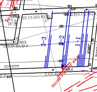
Three sets of blast holes are arranged on the lifting machine lane of 211113 working face, as illustrated in Fig. 10. Among them, the 1-1 set includes 6 blast holes (hole numbers 1-6); the 2-2 set includes 4 blast holes (hole numbers 1, 2, 3 and 6); and the 3-3 set includes 3 blast holes (hole numbers 1, 2 and 3).
Fig. 10Layout of blast holes
The layout sections of first two sets are given in Fig. 11. The three sets of blast holes are all arranged on a straight line, with a spacing of 1.5 m. The blasting parameters of each set are listed in Table 3. The charge amount and length are 700 kg and 212 m for the 1-1 set, 551 kg and 155 m for the 2-2 set, and 350 kg and 106 m for the 3-3 set. In this charge process, water-gel explosive for coal mine gas drainage are used. The forced top caving is positioned 5 m away from the working face (The blue lines in Fig. 11 are the blast holes.). Starting from 5 m in front of the working face, each set of the blast holes are preliminarily arranged every 20 m according.
Fig. 11Layout profile of blast hole
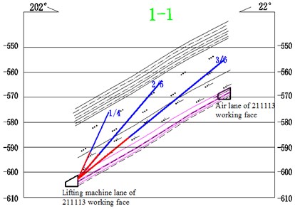
a)
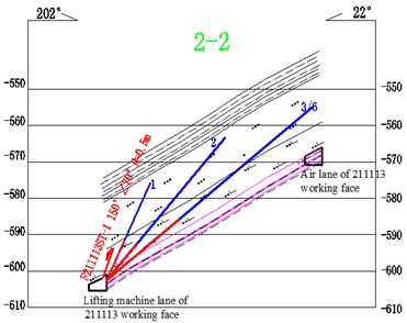
b)
Table 3Blasting parameters
Position | Number of hole | Length of blast hole /m | Elevation angle / ° | Size of hole / mm | Length of charge / m | Length of hole sealing / m |
Machine lane | 1 | 30 | 65 | 75 | 18 | 12 |
2 | 52 | 49 | 75 | 39 | 13 | |
3 | 76 | 39 | 75 | 49 | 27 | |
4 | 30 | 65 | 75 | 18 | 12 | |
5 | 52 | 49 | 75 | 39 | 13 | |
6 | 76 | 39 | 75 | 49 | 27 |
5.2. Effect of field application
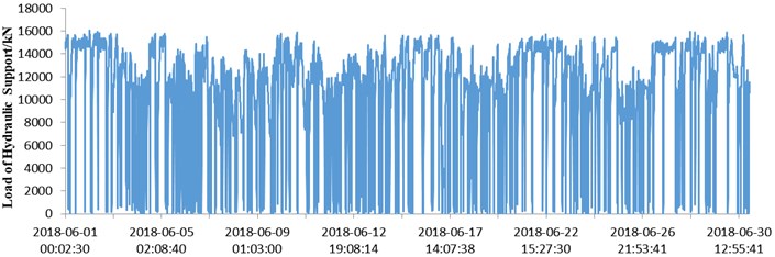
The working face resistance recording system (KJ20) produced by Tiandi Technology Co., Ltd. was used to monitor the working face resistance of the hydraulic support during the “short-face” mining. The two sensors of each measuring point recorder serve to monitor the working resistances at the left front pillar and the right rear pillar, respectively. The vibration frequency of the hard roof increases linearly with the increase of the distance from the source, and the vibration amplitude decreases exponentially with the increase of the distance from the source within 20 m from the blasting relief hole. According to the mining pressure data obtained from June 1st to June 30th, 2018, the working face advanced at a stable speed by about 144 m (150 knives) in total, with an average advancement speed of 6 knives/day and 4.8 m/day. In this process, the overall working resistance variation of the hydraulic support on the working face is shown in Fig. 12.
From Fig. 12, it can be concluded that after the roof was weakened by the advanced deep-hole pre-splitting blasting, the working face experienced a periodic weighting with a distance of about 17.7 m, and the distance of continuous weighting averages about 6.9 m. This shows that the deep-hole pre-splitting blasting weakening management of the roof in the early stage of working face recovery achieved good results and effectively ensured safe and efficient recovery of the working face.
Fig. 12Curve of overall working resistance variation of hydraulic support on working face
6. Conclusions
1) Through the theoretical analysis and calculation of ultimate falling distance and the maximum overhanging arch length of the 211113 working face, it is concluded that the ultimate falling distance of #11-2 coal is 132.11 m, and the maximum overhanging arch length is 25 m. These data provide a basis for determining the advanced roof caving in the early stage of mining.
2) The numerical simulation of “short-face” overlying strata recovery before and after the weakening indicates that due to the short length of the 211113 “short face” and the extra hard and thick quartz sandstone in the overlying roof, with the advancement of the working face, the principal area of stress concentration is mainly located at the hard roof with very limited roof subsidence and failure scope. After the advanced weakening technology is applied to the overlying strata, the principle stress distribution of surrounding rock in the stope has been greatly improved, and the overlying strata fall in time with the mining of the working face. Besides, the area of stress concentration extends outward and the degree of stress concentration is also significantly reduced. The distance for the first falling of “short-face” recovery reaches about 20-30 m, and the overlying strata fall off with mining.
3) After the roof was weakened by the advanced deep-hole pre-splitting blasting, the working face experienced a periodic weighting with a distance of about 17.6 m, and the distance of continuous weighting averages about 6.9 m. The blasting effectively prevents a large-area overhanging arch, realizes the extra hard and thick roof falling with mining in the ultra-short working face, and ensures the safe and efficient mining of the working face.
References
-
Chen Shancheng Geochemistry of Organic Carbon and Elements in Lower Permian Coal-bearing Rocks in Huainan Coalfield. China University of Science and Technology, Anhui, 2016.
-
Bai Q., Tu S., Wang F., Zhang C. Field and numerical investigations of gateroad system failure induced by hard roofs in a longwall top coal caving face. International Journal of Coal Geology, Vol. 11, Issue 1, 2017, p. 176-199.
-
Huang B., Liu J., Zhang Q. The reasonable breaking location of overhanging hard roof for directional hydraulic fracturing to control strong strata behaviors of gob-side entry. International Journal of Rock Mechanics and Mining Sciences, Vol. 103, Issue 6, 2018, p. 1-11.
-
Tan Y., Zhang Z. AE pattern of rock burst disaster induced by strata activation in coal mine. Disaster Advances, Vol. 44, Issue 2, 2011, p. 20-33.
-
Zhao H. Numerical simulation on pressure behavior of mining field under the conditions of hard roof. Disaster Advances, Vol. 4, Issue 1, 2017, p. 15-20.
-
Zhao T., Yin Y., Tan Y. Safe mining and new prediction model in coal seam with rock burst induced by roof. Disaster Advances, Vol. 54, Issue 10, 2014, p. 961-965.
-
Lü Jin-Guo, Jiang Yao-Dong, Li Shou-Guo Characteristics and mechanism research of coal bumps induced by faults based on extra thick and hard roof. Journal of China Coal Society, Vol. 39, Issue 10, 2014, p. 1961-1969.
-
Wang G., Wu M. M., Wang R., et al. Height of the mining-induced fractured zone above a coal face. Engineering Geology, Vol. 216, Issue 10, 2016, p. 140-152.
-
Wang P., Jiang J. Q., Zhang P. P., et al. Breaking process and mining stress evolution characteristics of a high-position hard and thick stratum. International Journal of Mining Science and Technology, Vol. 26, Issue 10, 2016, p. 563-569.
-
Zhu Qinghua, Wang Jicheng, Ma Zhenguo Numerical simulation of thick and hard roof breakage and caving in shallow seam. Journal of Mining and Safety Engineering, Vol. 21, Issue 4, 2004, p. 17-19.
-
Xia Binwei, Li Xiaolong, Lu Yiyu Numerical simulation of the effect on pressure relief by blasting in working face with rock burst. Journal of Mining and Safety Engineering, Vol. 33, Issue 6, 2016, p. 1038-1044.
-
Miao Xiexing, Qian Minggao The research of numerical modeling of destress blasting in a deep hard rock tunnel wall. Journal of China University of Mining and Technology, Vol. 29, Issue 1, 2014, p. 25-29.
-
Qian Minggao, Miao Xiexing Numerical simulation of rockburst prevention effect by blasting pressure relief in deep coal seam. Chinese Journal of Rock Mechanics and Engineering, Vol. 14, Issue 2, 1995, p. 97-106.
-
Lu Guozhi, Tang Jianquan, Song Zhenqi Theoretical model and numerical calculation of rock blasting. Chinese Journal of Geotechnical Engineering, Vol. 32, Issue 4, 2010, p. 538-541.
-
Wang F. T., Tu S. H., Yuan Y., et al. Deep-hole pre-split blasting mechanism and its application for controlled roof caving in shallow depth seams. International Journal of Rock Mechanics and Mining Sciences, Vol. 64, Issue 11, 2013, p. 112-121.
-
Konicek P., Soucek K., Stas L., et al. Long-hole destress blasting for rockburst control during deep underground coal mining. International Journal of Rock Mechanics and Mining Sciences, Vol. 61, Vol. 9, 2013, p. 141-153.
-
Konicek P., Saharan M. R., Mitri H. Destress blasting in coal mining–state-of-the-art review. Procedia Engineering, Vol. 26, Issue 3, 2011, p. 179-194.
-
Lu C. P., Liu Y., Wang H. Y., et al. Microseismic signals of double-layer hard and thick igneous strata separation and fracturing. International Journal of Coal Geology, Vol. 39, Vol. 10, 2016, p. 28-41.
-
Fan J., Dou L. M., He H., et al. Directional hydraulic fracturing to control hard-roof rock burst in coal mines. International Journal of Mining Science and Technology, Vol. 22, Issue 2, 2012, p. 177-181.
-
Wang X., Xu J., Zhu W., et al. Roof pre-blasting to prevent support crushing and water inrush accidents. International Journal of Mining Science and Technology, Vol. 22, Issue 3, 2012, p. 379-384.
-
Deng X., Zhang J., Benjamin W., et al. Pressure propagation characteristics of solid waste backfilling material during compaction and its applications in situ. Geotechnical and Geological Engineering, Vol. 34, Issue 4, 2016, p. 1631-1642.
-
Chen S. J., Wang H. L., Wang H. Y., et al. Strip coal pillar design based on estimated surface subsidence in eastern China. Rock Mechanics and Rock Engineering, Vol. 49, Issue 5, 2016, p. 3829-3838.
-
Ning J. G., Wang J., Bu T. T., et al. An innovative support structure for gob-side entry retention in steep coal seam mining. Minerals, Vol. 7, Issue 1, 2017, p. 961-973.
-
Kang H. P. Support technologies for deep and complex roadways in underground coal mines: a review. International Journal of Coal Science and Technology, Vol. 39, Issue 6, 2014, p. 261-277.
-
Yu Bin, Liu Changyou, Yang Jingxuan Research on the fracture instability and its control technique of hard and thick roof. Journal of China University of Mining and Technology, Vol. 42, Issue 5, 2013, p. 342-348.
About this article

This work was supported by the National Natural Science Foundation of China (51874006, 51774009), Anhui Provincial Natural Science Foundation (1808085ME134).
Yan Li mainly carried out and completed this work. Jucai Chang proposed this topic and supervised the work. Wenbao Shi and Zhiqiang Yin provided careful guidance for theoretical calculation and numerical simulation. And Jugen Fu provided data for engineering practice verification. All authors read and approved the final manuscript.
