Abstract
This paper offers an actuating equation for MFC arc-plate structures to obtain MFC’s accurate actuating force and actuating bending moment to are-plate structures and increase MFC control effect on vibration. This paper proposes the P1 type MFC arc-plate actuating equation which considers the recombination action of MFC and controlled structure, and arc-plate curvature influence on MFC, obtaining the MFC actuating force and actuating bending moment for arc-plate structures. The vibration control experiment of MFC arc-plate structures is performed, and the deviation between finite element simulation results adopting this equation and the experimental data is less than 8.5 %. The research shows that the P1 type MFC actuating equation deduced in this paper is correct and fully applicative to the MFC vibration control simulation to arc-plate structures.
1. Introduction
Currently, the widely used piezoelectric materials include piezoelectric crystal and piezoelectric ceramics which, however, as fragile materials with poor flexibility and elasticity, cannot bend and be applied to curved surface structures such as sphere or cylinder. To solve this problem, domestic and overseas scholars have developed a new type of piezoelectric material – macro fiber composite (MFC) which makes piezoelectric ceramics fibrous and then recombines it with organic polymer matrix according to different connection methods, volume ratios, and spatial distribution [1].
To conduct vibration control over arc-plate structure with MFC, MFC electromechanical coupling relationship is supposed to be understood to deduce the actuating equation of MFC arc-plate structures. Many scholars have studied MFC actuating equation recently. Shun-Qi Zhang et al. [2] have established the finite element model pasted with MFC cantilever by applying the linear piezoelectric constitutive equation based on Reissner-Mindlin theory, and studied the impact difference on cantilever deformation made by different arrangement modes of piezoelectric fibers under normal pressure. In allusion to the vibration created by the axial movement of cantilever, Guoliang Ma et al. [3] have deduced the free vibration equation about cantilever axial movement with Hamilton theory. They have considered MFC and the major structure separately and treated MFC impact on the major structure as external controlling force, thus simplifying the actuating equation and offering new thoughts for the research about MFC actuating equation. M. L. Dano and B. Jullière [4] have conducted active control over the thermal-induced deformation of cantilever with MFC and performed composite structure modeling and the experiment with finite element software, indicating that MFC has a remarkable effect on reducing the thermal-induced deformation of cantilever.
Based on those studies, this paper deduces the actuating equation which considers the recombination action between MFC and the controlled structure and the actuating force in the radial direction made by MFC influenced by the arc-plate curvature. The vibration control simulation over arc-plate structures and active control experiment are accomplished on the basis of the equation.
2. The actuating equation of MFC arc-plate structures
The two-dimensional constitutive equation of MFC linear-elastic piezoelectric material polarized in the direction of axis is written as:
where, is the flexibility coefficient of MFC, in which represents the MFC strain direction, and the MFC stress direction; is the piezoelectric strain coefficient of MFC, in which represents the direction of electric field action, the strain direction of piezoelectric material after electric field action, 1, 3 correspond to , directions respectively in Cartesian coordinate system; is electric field intensity in direction.
As is shown in Fig. 1, the thickness of two-dimensional MFC arc-plate structure is ; MFC effective length is , width , and thickness ; is the surface distance between the structural neutral axis and the controlled structure. Since MFC thickness is extremely small, it is approximately assumed that .
From Eq. (1) the two-dimensional MFC stress is:
in which is MFC Poisson’s ratio; is elasticity modulus of MFC.
The actuating bending moment of MFC per unit length for two-dimensional arc-plate structure is:
According to deformation theory, the strain of two-dimensional MFC structure can be represented by bending moments and :
in which is elasticity modulus of the controlled structure; , the inertia moments of arc-plate intersecting surface coiling MFC horizontal and vertical neutrospheres respectively.
By substituting Eq. (4) into Eq. (3), it is obtained that:
in which:
Therefore, the actuating force of MFC is:
in which is the radius of arc-plate, and is the radian occupied by MFC.
Fig. 1The unit structure of MFC arc-plate
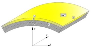
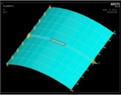
Fig. 2ANSYS model of MFC arc-plate structure
3. The experimental verification of the actuating equation of MFC arc-plate structures
To verify the correctness of the equation, the P1/ type MFC is attached to the arc-plate structure to perform analogue simulation and vibration control experiment.
Table 1Material properties
Material | Arc-plate (aluminum) |
Elasticity modulus | 70.5 GPa |
Density | 2700 kg/m3 |
Poisson’s ratio | 0.30 |
Width/Span | 350 mm |
Width | 400 mm |
Thickness | 2 mm |
Height | 55 mm |
To begin with, the arc-plate structure is modeled with ANSYS, whose parameters are shown in Table 1. Then the exciting force, MFC actuating force and actuating bending moment are defined, the exciting position located in the center of the arc plate and MFC actuating position at the red lines in Fig. 2. The obtained , and , are applied at the node located at the red lines in Fig. 2, and the obtained actuating force in the radial direction at each node surrounded by the red lines. In analogue simulation, the exciting force and MFC actuating force are both simple harmonic force and the exciting force is opposite to the displacement phase produced by MFC actuating force and actuating bending moment. In this paper, the exciting force includes three working conditions: 20 Hz, 10 N; 50 Hz, 10 N; and 100 Hz, 10 N, and MFC working voltage is 300 V.
Fig. 3Experimental system of MFC arc-plate

Fig. 4Experimental model of MFC arc plate
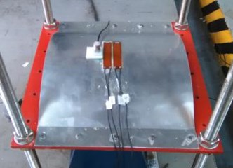
In vibration control experiment of MFC arc plate, the arc plate and MFC parameters are consistent with simulation. The key instruments include acceleration sensor, MFC, exciter, power amplifier, and dSPACE real-time simulation system which is shown in Fig. 3. Three sinusoidal signals are output by dSPACE (20 Hz, 50 Hz and 100 Hz) to provide the exciter and MFC with exciting signals, and the signal phase of the exciter is opposite to that of MFC. The experimental model is illustrated in Fig. 4.
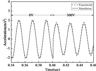
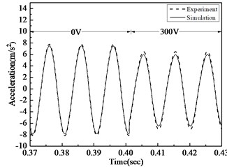
Fig. 5Acceleration comparison of simulation and experiment before and after control under 20 Hz, 50 Hz, 100 Hz excitement
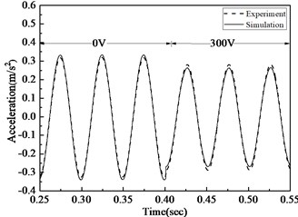
a) Acceleration comparison before and after 20 Hz arc-plate control
b) Acceleration comparison before and after 50 Hz arc-plate control
c) Acceleration comparison before and after 100 Hz arc-plate control
In Fig. 5, acceleration time courses of analogue simulation and actual test are compared under different working conditions. It is evident that under three different working conditions, the deviation of simulation and experiment is less than 8.5 %, so the actuating equation deduced in this paper can correctly depict the strength and electricity relationship of MFC. When the exciting force is 20 Hz, 10 N and working voltage is 300 V, the monolithic MFC in the experiment can decrease acceleration amplitude by 9.54%; when the exciting force is 50 Hz, 10 N and the working voltage is 300 V, the monolithic MFC can decrease acceleration amplitude by 12.68 %; when the exciting force is 100 Hz, 10 N and the working voltage is 300 V, the monolithic MFC can decrease acceleration amplitude by 15.44 %. As a result, MFC can effectively decrease the vibration of arc-plate structures, esp. the high-frequency vibration.
4. Conclusions
This paper deduces the actuating equation of MFC arc-plate structures and verifies it through simulation and experiment, drawing the conclusions as follows:
1) The equation deduced in this paper considers the recombination action of MFC and arc-plate structures and the actuating force in the radial direction made by MFC under the impact of the arc-plate curvature, which indicates that MFC electromechanical coupling relationship for the arc-plate is more accurate and practical.
2) This paper describes the MFC active vibration control simulation and experiment for arc-plate structures. The research not only proves that the actuating equation proposed in the paper is correct and applicative to arc-plate structures, but also indicates that MFC has a good effect on vibration control of arc-plate structures.
References
-
Williams B. R., Park G., Inman D. J., Wilkie W. K. An overview of composite actuators with piezoceramic fibers. Proceedings of 20th International Modal Analysis Conference, 2002, p. 421-427.
-
Zhang Shun Qi, Li Ya Xi, Schmidt Rüdiger Modeling and simulation of macro-fiber composite layered smart structures. Composite Structures, Vol. 126, 2015, p. 89-100.
-
Ma Guoliang, Xu Minglong, An Zengyong, Wu Chengsong, Miao Weikai Active vibration control of an axially moving cantilever structure using MFC. International Journal of Applied Electromagnetics and Mechanics, Vol. 52, 2016, p. 967-974.
-
Dano M.-L., Jullière B. Active control of thermally induced distortion in composite structures using macro fiber composite actuators. Smart Materials and Structures, Vol. 16, 2007, p. 2315-2322.
About this article

This research work is supported by the Chinese National Natural Science Foundation, Project No. 51478372, Hubei Province Innovation Group Project, Project No. 2016CFA020 and the Fundamental Research Funds for the Central Universities, Project No. 2017-zy-055.
