Abstract
This article deals with numerical simulation of single stage gearbox dynamic behavior. At first, the whole methodology is verified by an experimental approach. To assess the effect of gear damage there are four variants calculated, the first variant is without damage and the other three variants are with incorporated damage in different position. The surface normal velocity on the gearbox housing is computed and compared among the individual variants as the most evaluating factor. Finally, this study proves that the numerical simulation is a useful tool at the development phase, as well as, at the testing phase to confirm if the dominant problem is caused by the tooth quality.
1. Introduction
Gearbox is one of the main components of wide range of various machines, especially in automotive industry. With the increasing number of electric vehicles, trains, trams and trolley buses in the city, the restrictions are getting stricter. Therefore, gearboxes are becoming one of the components which is investigated and optimized for noise emission. Nowadays gearboxes are becoming crucial components in cars concerning noise emission monitoring. This is the consequence of a continuous trend in decreasing of the engine noise. In some cases, at the developing phase, the gearbox can be a dominant source of noise, where the gears are changing, or at high torque moment and low motor rotational speed. This can occur in tractor powertrain, where gears are exposed to high torque at relatively low rotation. The gearbox in tram or train are exposed to high torque as well. All gearboxes are constructed with respect to torque and rotation speed range. At last but not least, the lifetime plays also an important role. On the other side, gearboxes have to be compact, producible and also the economical point of view has to be taken into account. Therefore, the producers of high torque gearboxes use numerical simulations to develop gearboxes with appropriate components. The final product testing and testing of appropriateness of tooth shape are necessary to verify numerical simulation and simultaneously to confirm that product meets the imposed restrictions.
In this paper the comparison of small tooth damage is presented. Because the transmission vibration and related noise is a very complex topic, it is necessary to include several rotational inner parts. Each design and modifications of all important parts have an influence on the mass/stiffness and damping value, thus the basic form of the dynamic motion equation can be used:
where stands for mass matrix, is the damping matrix, represents stiffness matrix, is the overall force vector and with its derivatives means generalized coordinates.
In case when the other parts, as engine, are not connected to the transmission, the dominant excitation is due to gear meshing phenomena [1]. In the end, the external surface of the transmission is in motion due to inner process, also accompanied by the noise emitting to the surroundings [2].
Knowledge of all parts’ natural frequencies is then an important input which significantly affects the transmission behavior. The main parts should be considered as flexible by using Craig Bampton (CB) reduction principle, which replaces real deformations with the simplified approximation established from the two variants of degrees of freedom multiplied by the special Craig-Bampton transform matrix, see Eq. (2):
where is the original vector of deformation, are the boundary degrees of freedom (DOFs), stands for interior DOFs, represents modal DOFs, is the identity matrix element, is rigid body matrix element and in the analogical way are the fixed base mode shapes matrix element.
2. Methods
The numerical simulation is a frequently used approach in research and developing phase of transmission [3]. In the presented paper the combination of multibody software ADAMS and finite element method (FEM) software ANSYS is used. To be able to notice and describe the gearbox behavior at different operating conditions the gear mesh contact, shafts, bearings and housing have to be included in the model.
The methodology is created and evaluated on the single stage gearbox similar to the one in [4]. The parameters of the single stage gearbox and validation with experiment measurement are thoroughly described in [5].
2.1. Finite element method
The finite element method is used for CB reduction of shaft and gearbox housing. The natural frequencies of housing and its shapes are compared and validated to the experimental approach. Another important variable input is the stiffness of each part, which is calculated by FEM. The stiffness of bearings is calculated on one segment and afterwards converted to the whole bearing.
The gear mesh stiffness is calculated for four variants of pinion. The gear has 27 and 31 teeth, respectively. The gear is designed for operation torque up to 500 Nm. The damage is presented on one tooth of pinion with 0.5 mm length and 0.25 mm depth in all three variants. The locations of damages are in third quarter of tooth height, as you can see on the cross-section of gear, Fig. 1.
Fig. 1A cross-section of gear
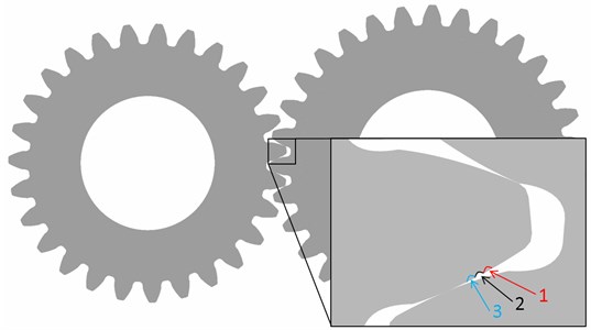
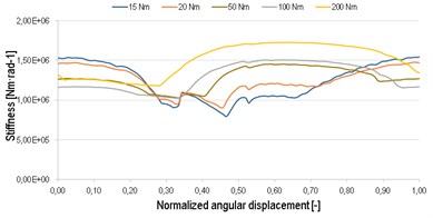
The stiffness is calculated for one tooth, which repeats periodically at gear without damage. The stiffness corresponds to the results, which are mentioned in [6]. Further, the stiffness is calculated for variants with damage. The damage is presented only on one tooth of pinion, thus every 27th stiffness was changed to the damage stiffness. The waveform of stiffness is changed for all three variants in comparison to variant without damage. The biggest change is in low loading, up to 50 Nm. The progress at high value of torque is almost without change, see Fig. 2. This stiffness is used in MBS simulation as inputs, see Fig. 3.
Fig. 2The gear meshing stiffness for each variant
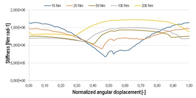
a) Gear meshing stiffness
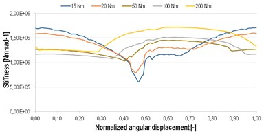
b) Gear meshing stiffness damage 1
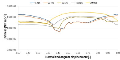
c) Gear meshing stiffness damage 2
d) Gear meshing stiffness damage 3
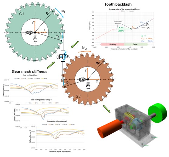
Fig. 3MBS model functional scheme
2.2. Multibody simulation
Multibody modelling respects experimental single stage gearbox mechanism, described in [5]. This gearbox consists of robust housing to avoid gearbox sides deformation, which can cause raise of transmission error. Only top lid cover is designed by modal properties to allow oscillation in frequency range 0-3000 Hz. This is to increase the surface normal velocity results’ accuracy. The main excitation is provided by gear mesh stiffness variability during rotation with period equal one tooth angle. Stiffness is computed with nonlinear contact analysis by FEM. With respect to gearbox functional principle, vibrations are transferring as forces through gear wheels, which are considered to be rigid bodies, to flexible shafts. Modal properties of these parts are imported via Modal Neutral File (MNF), composed by CB reduction and in this model are incorporated torsional vibrations in torque chain and bending vibrations with impact on the gearbox housing. Resultant forces in bearing areas are transferred to the housing via bushing feature, which is represented by radial, axial and torsional combination of spring-damper elements. Modal properties of the gearbox housing are included by MNF as well. Evaluation of modal properties is performed by experimental modal analysis. Input shaft is driven by applied angular frequency with range 0-3000 rpm. To apply gear loading the output shaft is braked by torque 30 Nm and 100 Nm. Simplified scheme of MBS model structure is mentioned in Fig. 3.
3. Results
The simulations are performed in frequency range 0-3000 Hz. The multispectrum diagrams for loading torque 100 Nm and 30 Nm are shown in Fig. 4. The amplitude is presented by vibration velocity level, with reference value 10-9 m∙s-1.
Fig. 4Multispectrum diagram for torque 100 Nm and 30 Nm
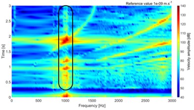
a) Without tooth damage, 100 Nm
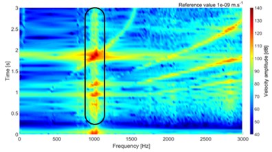
b) Tooth damage 1, 100 Nm
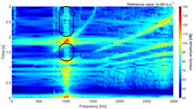
c) Without tooth damage, 30 Nm
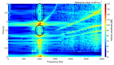
d) Tooth damage 1, 30 Nm
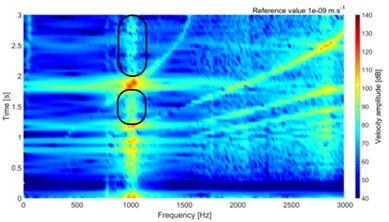
e) Tooth damage 2, 30 Nm
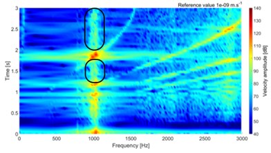
f) Tooth damage 3, 30 Nm
4. Conclusions
The combination of FEM and MBS is used for the gearbox behavior prediction. Each part of the methodology is validated separately by an experimental approach. The tooth damage is modeled by removing material in three different positions in the third quarter of tooth on pinion. Each damage is across the whole pinion width, 0.5 mm long and 0.25 mm deep. The mesh stiffness of each variant is calculated separately, where the progress of stiffness is significantly different at low torque. Only small stiffness progress change is at torque higher than 100 Nm. The numerical simulation of dynamic behavior is performed on the single stage gearbox without any other attached component, thus the excitation is due to the inner process and gear meshing stiffness, respectively.
The results show small difference at the peak of surface normal velocity on the top cover, which is significantly thinner than any other part of the gearbox. Small changes are visible on multispectrum diagram, which are highlighted in Fig. 4. The differences are visible on low and high values of torque. The small difference value is due to small damage, which is presented only on one tooth.
The results show that the effect of tooth small damage could be predicted by numerical approach. The parametrical study of damage dimension could show trends of gearbox behavior.
References
-
Tuma J. Vehicle Gearbox Noise and Vibration: Measurement, Signal Analysis, Signal Processing and Noise Reduction Measures. John Wiley, Chichester, 2014, p. 243.
-
Novotny P., Pistek V. New efficient methods for powertrain vibration analysis. Proceedings of the Institution of Mechanical Engineers, Part D, Journal of Automobile Engineering, Vol. 224, Issue 5, 2010, p. 611-629.
-
Kumar A., Jaiswal H., Jain R., Patil P. P. Free vibration and material mechanical properties influence based frequency and mode shape analysis of transmission gearbox. Procedia Engineering, Vol. 97, 2014, p. 1097-1106.
-
Loutas T. H., Sotiriades G., Kalaitzoglou I., Kostopoulos V. Condition monitoring of a single-stage gearbox with artificially induced gear cracks utilizing on-line vibration and acoustic emission measurements. Applied Acoustics, Vol. 70, 2009, p. 1148-1159.
-
Prokop A., Rehak K., Zubik M., Novotny P. Experimental validation of the gearbox NVH parameters. Journal of Middle European Construction and Design of Cars, Vol. 13, Issue 2, 2015, p. 16-21.
-
Kiekbush T., Sppok D., Bernd S., Ian H. Calculation of the combined torsional stiffness of spur gears with two- and three-dimensional parametrical FE models. Journal of Mechanical Engineering, Vol. 57, 2011, p. 810-818.
About this article
The research leading to these results has received funding from the Ministry of Education, Youth and Sports under the National Sustainability Programme I. (Project LO1202) and with help of the Project FSI-S-11-8 granted by specific University Research of Brno University of Technology. The authors gratefully acknowledge this support.
