Abstract
The problem of straight-line path following for asymmetric unmanned platform exposed to unknown disturbances was addressed in this paper. The mathematical model of asymmetric unmanned platform was established and the inputs in sway and yaw directions were decoupled, which facilitated the establishment of control strategy of path following. The guidance law and the cross-track error were derived from the classical line-of-sight (LOS) guidance principle. And the equilibrium point of the cross-track error was proven to be uniformly semiglobally exponentially stable (USGES), which guaranteed the exponential convergence to zero. A new disturbance estimation law was developed by adding a linear item of the estimation error into the classical one, which improved the principle’s precision and sensitivity dramatically. The control strategy was developed based on the integrator backstepping technique and the new disturbance estimation law, which made the equilibrium system to be uniformly globally asymptotically stable (UGAS). Computer simulations were conducted to verify the effectiveness of the estimation and control laws during straight-line path following for asymmetric unmanned platform in the presence of unknown disturbances.
1. Introduction
Unmanned platforms, as a kind of surface vessels, rely heavily on the guidance systems to accomplish path following scenarios [1], especially for asymmetric ones exposed to environmental disturbances such as wind, waves and currents. An overview of path following methods for unmanned surface vessels has been developed in [2, 3]. The path following methods for underactuated vehicles in the presence of large modeling parametric uncertainty using adaptive supervisory control that combines logic-based switching with Lyapunov-based techniques are discussed in [4]. An alternative model-based approach for robust adaptive path following is proposed in [5] and [6] on the basis of adaptive sliding mode control. The same problem was investigated in [7-9]. In [7, 9], the problem was formulated by a global diffeomorphism combined with backstepping technique, while in [8] was formulated by applying Serret-Frenet frame and model predictive control method. All the aforementioned references propose strategies under the assumption that the vessel is completely symmetric, which doesn’t really hold in practice. The path following for asymmetric vessels has also been discussed in [10-13]. [10, 11] decoupled the asymmetric system into two cascaded subsystems after two times diffeomorphism, and achieved the convergence of the tracking errors at the cost of the computation speed. [12, 13] proposed a simple-structure controller on the basis of line-of-sight (LOS) guidance principle and managed to steer an asymmetric vessel to follow the predefined path. But LOS is susceptible to environmental disturbances, and [12, 13] simply discussed the path following problem in the presence of constant ocean currents, it is necessary to continue studying methodologies that are robust to disturbances such as wind, waves and currents.
Motivated by [12, 13], based on an asymmetric unmanned platform this paper proposes a new simpler disturbance estimation law by adding a linear item of the estimation error into the classical one, then an adaptive path following controller is established based on the integrator backstepping technique, which makes the equilibrium system to be uniformly globally asymptotically stable (UGAS).
2. Mathematical model and problem statement
In this section, we will present the control objective and mathematical model of the platform considered in this paper.
2.1. Mathematical model
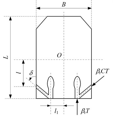
The unmanned platform is an approximately cubic port-starboard symmetric tank [14] with two nozzle-fixed but opening-adjustable waterjets located on both sides at a distance of 2, as is illustrated in Fig. 1, and a differential thrust steering scheme is therefore used. While there’s a difference in the openings of the left and right nozzle, i.e. , the yaw moment would produce. There are two reversing tunnels connected with the nozzles, where the extra water could squirt out to lateral anterior at an angle when the outlet of the nozzle is closing. denotes the longitudinal distance from the center of the reversing tunnel outlet to point , where represents the center of gravity of the platform. For simplicity, we assume that the thrust force produced by a single waterjet has a linear relationship with its nozzle opening [15], which is reasonable in practice. Consequently, applying the geometry yields:
where , and denote the overall length and beam of the platform; and denote the surge and sway thrust forces, respectively, denotes the yaw moment. and denote the reversing thrust factor and the thrust deduction fraction, respectively; and denote the effect coefficients imposed on sway and yaw directions by the propellers.
Fig. 1The structure sketch of unmanned amphibious platform
Obviously, it follows Eq. (1) that:
where .
Remark 1: Eq. (2) is nontrivial since the decreasement of control inputs would simplify the structure of path following controller.
In most cases, it is sufficient to consider a 3 degree-of-freedom (DOF) horizontal non-linear maneuvering model [16-18] which is shown that:
where denotes earth-fixed position coordinates and heading angle, denotes the body-fixed velocities.
The matrices in Eq. (3) can be expressed as:
where , , and are the rotation, inertia, Coriolis/centripetal and damping matrices, respectively.
The control inputs are: and all the forces and moments caused by wind, ocean current, second order wave loads, are collected in the vector: . Since these disturbances are bounded and so slowly varying compared to the platform dynamics, it is reasonable to assume that and in the controller synthesis.
2.2. Problem statement
The primary objective of this paper is to design a guidance and control system to steer the platform to converge to the predefined path with the desired speed from any initial positions and orientations despite of the environmental disturbances.
3. LOS guidance system design
The LOS guidance law is a three-point guidance scheme for it involves a stationary reference point on the path in addition to the vessel and the desired position, mimicking a helmsman that commonly makes the vessel pursue the desired path through steering it towards a point located at a constant distance ahead of the vessel on the path [17, 18].
3.1. The desired heading angle
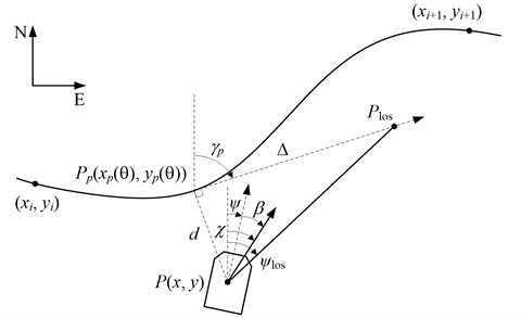
A parameterized path (, ), where 0 denotes the path variable, is assumed to go through a set of successive waypoints for 1, 2, …, , as illustrated in Fig. 2. For any point (, ) along the path, the path-tangential reference frame is rotated by an angle:
with respect to the North-East reference frame. Note that for a straight line is constant between the waypoints. For a platform located at the position (, ) the LOS vector starts from (, ) and ends up with the point (, ), located on the path tangential at a distance 0 ahead of the orthogonal projection of point (, ). And the orientation of the LOS vector is donated as :
where is the cross-track error, and is the lookahead distance.
Fig. 2LOS guidance geometry
In LOS guidance system, the moving point (, ) and the orientation angle are the desired point and angle that the platform is chasing for at each time instant. Consequently, the corresponding LOS guidance law is given by:
Commonly, a vehicle exposed to disturbances (such as wind, waves and ocean currents, etc.) exhibits variations in the velocities , and . The response can be observed as a non-zero sideslip angle during path following. This is also observed as a difference in heading angle and course angle according to:
where .
This suggests that the LOS guidance law is chosen as:
where .
3.2. The cross-track error
The cross-track error is computed as the orthogonal distance to the path-tangential reference frame defined by the point (, ). Hence:
where .
Expanding Eq. (8) gives the cross-track error:
where propagates [13] according to Eq. (10):
Differentiating Eq. (9) yields:
The last bracket in Eq. (11) is zero because of the first line of Eq. (8). From Eq. (4) it follows that . Consequently, Combine Eq. (3) and (11) yield:
where .
In this paper we consider the special case where is constant, that is straight-line paths such that:
Theorem 1: The LOS guidance law Eq. (7) applied to the cross-track error dynamics Eq. (13) renders the equilibrium point 0 USGES if the lookahead distance and speed satisfy and , respectively.
Proof. Inserting Eq. (7) into Eq. (13) gives:
Since and is time varying the system Eq. (14) is nonautonomous. Consider the Lyapunov function candidate: 0 when 0. Hence:
Since and it follows that:
Therefore, according to [19, 20] the origin 0 is uniformly stable.
Next, we define:
For each 0 and all , we have:
Consequently:
In view of Eq. (15), the above holds for all trajectories generated by the initial conditions d(t0). Consequently, we have:
for all , and 0.
Hence, we can conclude that the equilibrium point 0 is USGES.
4. Control system design
In this section, a model-based control method is performed by utilizing the integrator backstepping technique for the nonlinear maneuvering system Eq. (3) to design a uniformly globally asymptotically stable (UGAS) controller. And the design is divided into two coherent steps.
The overall design is conducted under the assumptions that all the reference signals are bounded and high order differentiable.
The heading angle and the velocity error dynamics are defined as:
where , and is a vector of stabilizing functions to be specified later.
Step 1. Define the first Lyapunov function candidate as: when . Hence:
Choosing:
where 0, gives:
This concludes Step 1.
Step 2. Combine Eq. (3) and differentiate Eq. (17) yields:
Next, we need to expand the first Lyapunov function as:
where and 0 is the estimation error and gain matrices, respectively. is the estimation of the environmental disturbance vector . It should be noted that is slow varying and bounded, therefore, . Differentiating along the trajectories of , , gives:
Choosing the control input and the disturbance estimation law:
where and are positive matrices to be specified, gives:
It follows from the theorems proposed by [17, 20] that is uniformly stable.
Remark 2: Compared with the law developed by [17], Eq. (21) contains an additional item , which realizes the negative feedback regulation of , and when approaches to its equilibrium point the estimation error will converge to zero exponentially.
Because of the uniform stability of we have . Considering the control objective is to steer the platform travelling at the desired speed , it is reasonable to choose .
Combining Eq. (2) and (20) gives:
where:
Theorem 2: The platform dynamics Eq. (3) with guidance, control and estimation laws Eqs. (7, 20, 21) renders the origin of the error system Eqs. (13), (16), (17) UGAS.
Proof. We can prove the Theorem 2 based on the control design and stability analysis above.
5. Simulations
In this section results from numerical simulations are presented. The developed control strategy is applied to an asymmetric unmanned platform. The vehicle has a 10 kN of maximum thrust for every waterjet, and other parameters are shown as follows [14]:
The objective is to make the platform follow the predefined path with a desired surge speed 3 m/s. The path is chosen as a straight-line passing through point (5 m, 12 m) with a slope angle /6. The environmental disturbances presenting on the platform is bounded and slow variable, without loss of any generality, we here assume that the disturbances are generated as in Eq. (23).
To make the controllers Eq. (20-21) follow the desired references smoothly and estimate the disturbances precisely, the following gains are implemented: 5, 30, diag{3000, 1.5, 0.5}, diag{1, 1, 2}, diag{0.8, 0.5, 0.3}, 14.94. The platform is given an initial state of (20 m, 0 m, 0 rad/s, 1 m/s, 0 m/s, 0 rad/s).
Fig. 3Straight-line path following of the platform
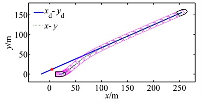
Fig. 4Time evolution of the platform’s states
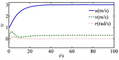
a) State of
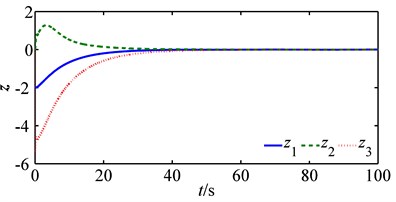
b) State of
Fig. 3 shows how the path following is successfully achieved under control and estimation laws Eqs. (20-21). Fig. 4 shows all the platform’s states converge to equilibriums smoothly, and Fig. 5 shows a graceful time evolution of control inputs without saturation. Fig. 6 is a comparison between the estimation law Eq. (21) and that of [17] (denote the estimation law Eq. (21) as and that proposed in [17] as for simplicity). Fig. 6 is the time evolution of disturbance estimation errors, and Fig. 6(a) is the result of and Fig. 6(b) of with diag{200, 200, 400}. As is shown in Fig. 6(a), the disturbance estimation error converges exponentially to zero and stays at that equilibrium point afterthen, which coinsides well with our previous analysis. On the contrary, Fig. 6(b) shows the maximum of estimation error is nearly 20 kN, which might lead to saturation for control inputs. As a result, it is obvious to conclude the better performance of than that of .
Fig. 5Time evolution of control inputs
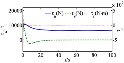
Fig. 6Time evolution of the disturbance estimation errors
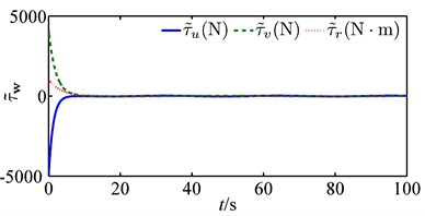
a)
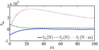
b)
6. Conclusions
A nonlinear adaptive path following strategy for estimation and compensation of the disturbances has been presented on the basis of integrator backstepping technique. The guidance law is derived from the classical LOS principle and the equilibrium points of the cross-track error is shown to be USGES, which guarantees the exponential convergence to zero. A new estimation law for disturbances is developed by adding a linear item of the estimation error into the classical one, which improves the estimation precision and sensitivity dramatically. The control strategy is developed based on the integrator back- stepping technique and the new disturbance estimation law, which makes the equilibrium system to be UGAS. In the end, computer simulations are conducted to verify the effectiveness of the control and estimation laws during straight-line path following for asymmetric unmanned platform in the presence of unknown disturbances.
References
-
Breivik M., Hovstein V. E., Fossen T. I. Straight-line target tracking for unmanned surface vehicles. International Journal of Modelling, Identification and Control, Vol. 29, Issue 4, 2008, p. 131-149.
-
Liao Yu Lei, Zhang Ming Jun, Dong Zao Peng, et al. Methods of motion control for unmanned surface vehicle: state of the art and perspective. Shipbuilding of China, Vol. 55, Issue 4, 2014, p. 206-216.
-
Liu Chen Guang, Chu Xiu Xin, Wu Qing, et al. A review and prospect of USV research. Ship Building of China, Vol. 55, Issue 4, 2014, p. 194-205.
-
Aguiar A. Pedro, Hespanha Joao P. Trajectory-tracking and path-following of underactuated autonomous vehicles with parametric modeling uncertainty. IEEE Transactions On Automatic Control, Vol. 52, Issue 8, 2007, p. 1362-1379.
-
Liao Yu Lei, Zhang Ming Jun, Wan Lei Serret-Frenet frame based on path following control for underactuated unmanned surface vehicles with dynamic uncertainties. Journal of Central South University, Vol. 22, Issue 1, 2015, p. 214-223.
-
Cheng Liu, Jian Zou Zao, Shan Li Tie Adaptive robust sliding mode control for ship straight-line tracking in random waves. Journal of Shanghai Jiaotong University (Science), Vol. 18, Issue 5, 2013, p. 549-553.
-
Ghommam J., Mnif F., Derbel N. Global stabilization and tracking control of underactuated surface vessels. IET Control Theory and Applications, Vol. 4, Issue 1, 2010, p. 71-88.
-
Wang Xiao Fei, Zou Zao Jian, Li Tie Shan, et al. Adaptive path following controller of underactuated ships using Serret-Frenet. Journal of Shanghai Jiaotong University (Science), Vol. 15, Issue 3, 2010, p. 334-339.
-
Wang Yao Lu, Guo Chen Path flowing adaptive control for underactuated surface vessels based on RBF neural network. Journal of Dalian Maritime University, Vol. 41, Issue 1, 2015, p. 1-5.
-
Wan Lei, Dong Zao-Peng, Li Yue-Ming, et al. Global asymptotic stabilization control of incomplete symmetry underactuated USV. Journal of Huazhong University of Science and Technology (Natural Science Edition), Vol. 42, Issue 8, 2014, p. 48-53.
-
Zhang Zhong Cai, Wu Yu Qiang Switching-based asymptotic stabilization of underactuated ships with non-diagonal terms in their system matrices. IET Control Theory and Applications, Vol. 9, Issue 6, 2015, p. 972-980.
-
Caharija Walter, Candeloro Mauro, Pettersen Kristin Y., et al. Relative velocity control and integral LOS for path following of underactuated surface vessels. 9th IFAC Conference on Manoeuvring and Control of Marine Craft. Arenzano, Italy: 2012.
-
Fossen Thor I., Pettersen Kristin Y., Galeazzi Roberto Line-of-sight path following for Dubins paths with adaptive sideslip compensation of drift forces. IEEE Transactions On Control Systems Technology, Vol. 23, Issue 2, 2015, p. 820-827.
-
Ju Nai Jun Hydrodynamics Analysis and Simulation for Amphibious Vehicle. Weapon Industry Press, Beijing, 2005.
-
Hua Yu Long, Chi Bao Shan, Sun Wei, et al. Study on motion model of twin-propeller unmanned amphibious platform. Machinery Design and Manufacture. Vol. 9, 2015, p. 37-40.
-
Breivik M., Fossen Thor I. Guidance-based path following for autonomous underwater vehicles. Proceedings of OCEANS 2005 MTS/IEEE, Washington, D.C., 2005, p. 2807-2814.
-
Wang Hao Duo, Wang Qin Ruo, Wu Xiao Ze Uniformly globally asymptotically stable path following with integral gain-variable guidance law for ships. Control Theory and Applications, Vol. 32, Issue 6, 2015, p. 849-856.
-
Fossen Thor I. Models for Ships, Offshore Structures and Underwater Vehicles. Handbook of Marine Craft Hydrodynamics and Motion Control, John Wiley and Sons Ltd., Chichester, UK, 2011.
-
El-Sayed A. M. A., Nasr M. E. Existence of uniformly stable solutions of nonautonomous discontinuous dynamical systems. Journal of the Egyptian Mathematical Society, Vol. 19, 2011, p. 91-94.
-
Fossen Thor I., Pettersen Kristin Y. On uniform semiglobal exponential stability (USGES) of proportional line-of-sight guidance laws. Automatica, Vol. 50, Issue 11, 2014, p. 2912-2917.
About this article

The authors gratefully acknowledge the support of the Development Center of Equipment and Technology.
