Abstract
This paper focuses on the assessment of modal forms of the alignment leveling table and their impact to the angle measurement accuracy of circular scales. It also addresses the impact of the experimental stand structure to the measurement of these scales. Even though the performed investigations are used to determine the precision of a specific angle measurement system, the findings do have a wider range of applications and can be used for the development of precision measurement instruments. Experimental and numerical investigations are used to illustrate the efficiency and effectiveness of the proposed alignment-leveling table.
1. Introduction
Angle measurement scales are used as standard measures for angular displacements in machine-tools, coordinate measurement systems and other measurement devices. One of the most important characteristics of these measures is the error of the position of the grating lines. Though actual positions of these lines can be determined by calibration, the production of such measures is only possible after solving the problem of its relationship to the angle unit standard. A typical example of such calibration is discussed in [1] where the uncertainty of the angle comparator is analyzed at the Korean Research Institute of Standards and Science (KRISS). The performance of the angle generator was evaluated and assessed during the calibration of several angle standard and instruments. The nonlinearity error of the angle readout and a new calibration strategy for the reduction of this error are investigated in [1].
A new setup for vertical angle measuring system calibration along with the methodology of its calibration is presented in [2]. The sources of measurement errors are analyzed as combined uncertainty components such as uncertainties induced by the indexing table and autocollimator, limited display resolution and the repeatability of the devices. The adjustment of the mounting device to the axis of rotation of the table is proposed in [3]. The mounting device is positioned on the indexing table and adjusted by probing the mounting shaft with a precision indicator.
A six degrees of freedom measurement system using capacitive sensors with nanometer resolution is developed using a low-noise level detector and highly stable electronics [4]. A novel alignment mechanism integrating functions of both leveling and centering is designed and fabricated in [5] by introducing multi-layered orthogonal connected flexible hinges as the key supporting and joining elements in order to eliminate the effects of motion coupling for measuring cylindrical work pieces. It is shown that the leveling adjustment is the important part and precondition of the alignment. On the basis of a correlative leveling adjustment technology, a novel optical alignment system for leveling adjustment is presented [6]. A system for a step-gauge calibration using a conventional coordinate measuring machine combined with an interferometer for the evaluation of the measurement uncertainty is described in [7]. Automatic high-precision chip mounters have been successfully applied in high-precision and complex craft situations [8] where the key element of the calibration equipment is the vision alignment system. Other new original stability evaluation techniques for the alignment-leveling table are discussed and developed in [9-21]. Measuring scale errors in a laser tracker's horizontal angle encoder by employing simple length measurement and two-face system are assessed in [22]. The measurement analysis of raster scales and their applications in modern measurement technology are presented in [23-28]. However, the following theoretical and technical problems still remain relevant in this field precision engineering:
– the development of methods and implementations for limbs and raster scales measurements, which would allow to increase the number of measured values and provide access to both discrete and analogue measurement information;
– the development of methods dealing with the measurement problems of small diameter limbs and length scales of small dimensions;
– the development of new methods and implementations for informational measurement systems and the increase of accuracy in angle and length measures.
The objective of this paper is to develop a new angle measurement system based on circular scales. The algorithm for the establishment of position of grating lines, its analysis and optimization, the analysis of angular errors emerging from the circular scale production technology, means and methods of their compensation comprise the problems to be solved in the process of the development of the alignment-leveling table.
2. Analytical and experimental studies of the alignment-leveling table
Analytical and experimental studies of the new adjustment mechanism (alignment-leveling table) are presented in this section.
2.1. The object of research
Our proposed alignment and leveling structure is comprised from the table frame (outer ring) containing all other parts of the mechanism; the aligned-leveled disk (inner ring); the bottom ring used for attaching the table to other measurement systems; two alignment-leveling micro-feeds; and the elements for micro-feed transfer (springs, conical nozzles, etc.) (Fig. 1).
The adjustment table of optical and geodesic devices has two pairs of adjustment mechanisms. The position of alignment and leveling is controlled in the same plane, in the two perpendicular axes in relation to one another. This mechanism (Fig. 1 and Fig. 2) differs from the others due to the facility to simplify and increase its accuracy.
Fig. 1The structure of the alignment table: 1 – table frame, 2 – disk, 3 – alignment-leveling micro-feeds
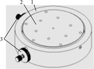
Fig. 23D model section of the table: 1 – table frame, 2 – immobile plate, 3 – moving disk, 4 – frame of alignment-leveling mechanism, 5 – micro screw, 6 – sleeve, 7 – beads, 8 – conical nozzles, 9 – spring, 10 – fixation screw
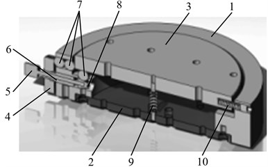
Alignment-leveling micro mechanisms are installed concentrically in the two perpendicular axes and their feed is transferred to the two disc thrusts. In order to increase the displacement accuracy and the resolution of the mechanism, both concentric mechanisms are installed in a way that allows them to operate independently. The alignment position is controlled via two rings; their surface has 0.2 mm incline. In this way they operate concentrically by moving the inner ring through the shots in the right direction. The alignment is done moving a microscope until the disc position corresponds to the rotation position (center-wise).
The leveling position is controlled via two screw cams, which have conical grinded nozzles attached to their bottom. The screws can be rotated to both directions – thus the sliding conical nozzle levels the inner ring into the right position through the shots. The springs support the tightness and keep the disc compacted with the adjustment mechanism. Leveling is also performed while observing the object through a microscope or having an indicator leaning against it till the disc reaches its right position.
2.2. The model of the alignment-leveling table
The behavior of any elastic object interacting with dynamic forces can be specified by the dynamic equilibrium equation [29]:
where , , are the mass, damping and stiffness matrices, respectively; is the vector of external mechanical forces; are the vectors of accelerations, velocities and displacements, respectively.
For the three dimensional elastic structure, the mass matrix has the form:
where is the density of the material of the structure, is the volume of the finite element, [] is the matrix of the shape functions of the Lagrange finite element. The stiffness matrix has the form:
where:
and where is the modulus of elasticity and is the Poisson ratio of the elastic material. The damping matrix is assumed as:
where is the coefficient of external damping and is the coefficient of internal damping. The solution of the system can be approximated by a linear combination of the eigenmodes:
where is the vector of the coefficients of the eigenmodes , ,…, Modal equations take the form:
where the modal damping is expressed as:
2.3. Active vibroprotection of the alignment-leveling table
It is assumed that the displacement sensors are placed at the nodes of the finite element mesh and correspond to the definite degrees of freedom. Thus the vector of registered displacements is expressed as:
where is a sensing matrix having one number equal to one in each row and the other numbers equal to zero. It is assumed that the excitation forces act to the nodes of the finite element mesh and correspond to definite degrees of freedom. Thus the force vector is expressed as:
where is an excitation matrix having one number equal to one in each column and the other numbers equal to zero, is the vector of forces of excitation sources. It is assumed that the control law corresponds to the following law:
where is the transformation matrix with constant coefficients. In this case the equations in modal coordinates have the form:
Note that the matrix is not diagonal and thus the modal equations are coupled. But by taking into account only the diagonal elements of this equation, it is possible to approximately decouple the system.
In case the velocity (not displacement) sensors are used, the vector of registered velocities is expressed as:
where is a velocity sensing matrix having one number equal to one in each row and the other numbers equal to zero. Then the control can be implemented in accordance to:
where is a velocity transformation matrix with constant coefficients. In that case, the equations in modal coordinates read:
Note that the matrix is not diagonal and thus the modal equations are coupled. But by taking into account only the diagonal elements of this equation, it is possible to approximately decouple the system, and this leads to a much simpler investigation of dynamics of the structure. In this case the total damping matrix has the form . It is recommended to choose the values of elements of the velocity transformation matrix from the condition that the approximately decoupled system would be critically damped. This ensures protection of the investigated table from harmful vibrations.
2.4. Results of investigations of the alignment-leveling table
The upper part of the alignment-leveling table is modelled by using finite element techniques in SolidWorks environment. Table 1 presents leveling table mesh information.
The modeling results are presented below. Fig. 3 shows the first 7 modes of the upper part of the table.
Fig. 3The first 7 modes of the upper part of the table
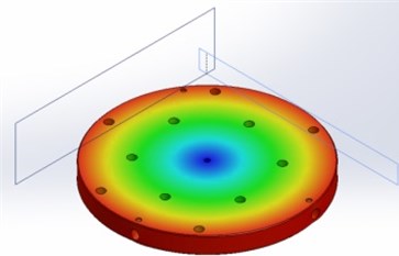
a) 298 Hz frequency
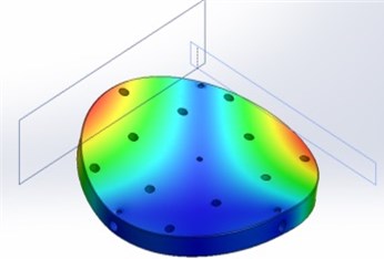
b) 431 Hz frequency
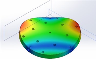
c) 593 Hz frequency
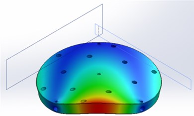
d) 1121 Hz frequency
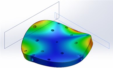
e) 2312 Hz frequency
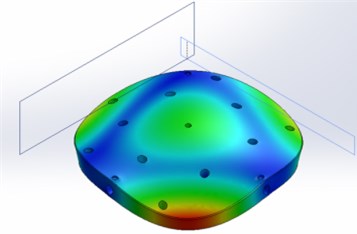
f) 2510 Hz frequency
Table 1Mesh information
Mesh type | Solid mesh | 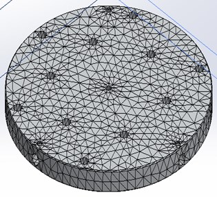 |
Mesher used | Standard mesh | |
Automatic transition | Off | |
Include mesh auto loops | Off | |
Jacobian points | 4 points | |
Mesh quality | High | |
Mesh information – details | ||
Total nodes | 22811 | |
Total elements | 14057 | |
Maximum aspect ratio | 12.264 | |
% of elements with aspect ratio < 3 | 92.6 | |
% of elements with aspect ratio > 10 | 0.0854 | |
% of distorted elements (Jacobian) | 0 | |
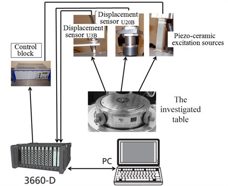
Experimental studies of the alignment table dynamics are performed in order to determine the mechanical instability of the system that influences the quality parameters of the system. For the identification of dynamic mechanical characteristics of the system, the block scheme of the experimental setup is given in Fig. 4; Table 2 shows the comparison between the theoretical and experimental results.
Measurement results show that the dominant frequencies are: 312 Hz, 423 Hz, 570 Hz (frequencies of modes 1, 2 and 3).
Table 2Comparison of theoretical and experimental results of the modal analysis
Modes | Theoretical | Graphical interpretation of measurements of table data using vibration sensors | ||
Frequency | Eigenmode | Frequency | Eigenmode | |
1 | 298 | 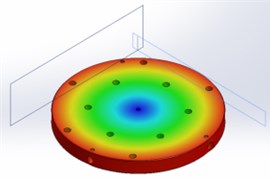 | 312 | 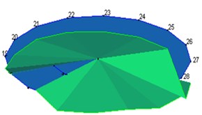 |
2 | 431 | 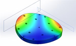 | 423 | 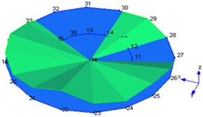 |
3 | 593 | 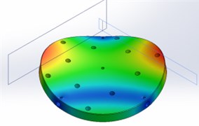 | 570 | 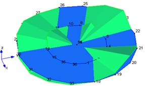 |
Fig. 4The schematic diagram of the experimental setup
3. Conclusions
A new circular scales alignment-leveling table was designed, produced and patented for the positioning of scales. The table is adapted to the optical scales measurement stand. The designed angle measurement system model allows the analysis of the characteristic oscillations of the angle measurement system. During the investigation of the oscillations of the alignment-leveling table of the angle measurement system, it was ascertained that the frequencies 312 Hz, 423 Hz and 570 Hz (modes 1, 2 and 3) reduce the accuracy of measurement in the process of performing of measurements.
References
-
Kim Jong-Ahn, Kim Jae Wan, Kang Chu-Shik, Jin Jonghan, Eom Tae Bong Calibration of angle artifacts and instruments using a high precision angle generator. International Journal of Precision Engineering and Manufacturing, Vol. 14, Issue 3, 2013, p. 367-371.
-
Suh Ho Suhng, Šiaudinytė Lauryna New setup for calibration of vertical angle measuring systems. 13th IMEKO TC10 Workshop on Technical Diagnostics. Advanced Measurement Tools in Technical Diagnostics for Systems’ Reliability and Safety, Warsaw, 2014, p. 27-31.
-
Yandayan T., Akgöz S. A., Haitjema H. A novel technique for calibration of polygon angles with non-integer subdivision of indexing table. Precision Engineering, Vol. 26, 2002, p. 412-424.
-
van der Lee Noenke, Kappelhof J. P., Hamelinck Roger Flexure-based alignment mechanisms: design, development, and application. Proceedings of SPIE 5176, Optomechanics, 2003.
-
Zhao Jian, Wang Hongxi, Gao Renjing, Hu Ping, Yang Yintang A novel alignment mechanism employing orthogonal connected multi-layered flexible hinges for both leveling and centering. Review of Scientific Instruments, Vol. 83, Issue 6, 2012, p. 065102-1-7.
-
Liu Wenchao, Zhong Yuning, Yang Liangen, Wang Xuanze, Xie Tiebang Development of a novel optical alignment system for accurate leveling adjustment of a high-precision chip mounter. Proceedings of SPIE 6280, Third International Symposium on Precision Mechanical Measurements, 2006.
-
Osawa Sonko, Takatsuji Toshiyuki, Kurosawa Tomizo Step-gauge calibration using an interferometric coordinate measuring machine and the uncertainty. Proceedings of XVII IMEKO World Congress, Dubrovnik, Croatia, 2003, p. 1911-1914.
-
Zhao J., Wang H., Gao R., Hu P., Yang Y. A novel alignment mechanism employing orthogonal connected multi-layered flexible hinges for both leveling and centering. Review of Scientific Instruments, Vol. 83, 2012, p. 065102-1-7
-
Gordeev S. V., Turukhano B. G. Investigation of the interference field of two spherical waves for holographic recoding of precision radial diffraction gratings. Optics and Laser Technology, Vol. 28, Issue 4, 1996, p. 255-261.
-
Korolev A. N., Gartsuev A. I., Polishchuk G. S., Tregub V. P. Metrological studies and the choice of the shape of an optical mark in digital measuring systems. Journal of Optical Technology, Vol. 77, Issue 6, 2010, p. 370-372.
-
Abbe M., Starrenburg M. P., Sawaabe M. Results from step gauge calibration using bi-axial laser interferometer. Proceedings of the 6th ISMQC IMEKO Symposium on Metrology for Quality Control in Production, Vienna, 1998, p. 9-13.
-
Shirmohammadi S., Ferrero A. Camera as the instrument: the rising trend of vision based measurement. IEEE Transactions Instrumentation Measurement, Vol. 17, Issue 3, 2014, p. 41-47.
-
Zhang S. Recent progresses on real-time 3D shape measurement using digital fringe projection techniques. Optics and Lasers in Engineering, Vol. 48, Issue 2, 2010, p. 149-158.
-
Ceccarelli M., Speranza A., Grimaldi D., Lamonaca F. Automatic detection and surface measurements of micronucleus by a computer vision approach. IEEE Transactions Instrumentation Measurement, Vol. 59, Issue 9, 2010, p. 2383-2390.
-
Martin D. The analysis of parasitic movements on a high precision rotation table. In MEDSI, Himeji, Japan, 2006.
-
Watanabe T. Is an angular standard necessary for rotary encoders. Synthesiology, Vol. 1, Issue 4, 2008, p. 296-304.
-
Watanabe T., Fujimoto H., Nakayama K., Kajitani M., Masuda T. Calibration of a polygon mirror by the rotary encoder calibration system. Proceedings of XVII IMEKO World Congress, Dubrovnik, Croatia, 2003, p. 1890-1893.
-
Just A., Krause M., Probst R., Wittekopf R. Calibration of high-resolution electronic autocollimators against an angle comparator. Metrologia, Vol. 40, 2003, p. 288-294.
-
Ng T. W., Lim T. S. Low-cost precision rotary index calibration. Proceedings of SPIE, Vol. 5879, 2005, p. 58790C.
-
Rashid Maki K., Khalil Zahi A. Tool orientation and motion error in microsurgical parallel manipulator. International Journal of Computer Application in Technology, Vol. 20, 2004.
-
Taek Oh Yeon Design of precision angular indexing system for calibration of rotary tables. Journal of Mechanical Science and Technology, Vol. 26, Issue 3, 2012, p. 847-855.
-
Muralikrishnan B., Blackburn C., Sawyer D., Phillips S., Bridges R. Measuring scale errors in a laser Tracker’s horizontal angle encoder through simple length measurement and two-face system tests. Journal of Research of the National Institute of Standards and Technology, Vol. 115, Issue 5, 2010, p. 291-301.
-
Kiryanov Alexey V. Accuracy enhancement for precision angle measuring structures. Key Engineering Materials, Vol. 437, 2010, p. 198-202.
-
Rybokas M., Bručas D., Šiaudinytė L., Pupeikienė L. Analysis of measurement system as a mechatronics system. Latest trends in engineering mechanics, structures, engineering geology. Proceedings of the 7-th International Conference On Engineering Mechanics, Structures, Engineering Geology, 2014, p. 113-115.
-
Sandwith Scott Thermal stability of laser tracking interferometer calibration. Manufacturing research and development. Dimensional Metrology R&D, Optics, 2011, p. 1-7.
-
Glennie Craig, Lichti Derek D. Static calibration and analysis of the velodyne HDL-64E S2 for high accuracy mobile scanning. Remote Sensing, Vol. 2, 2010, p. 1610-1624.
-
Schulz Michael, Fricke Andreas, Stock Klaus, Alvarenga Ana D., Belaidi Hakima High-accuracy polarimetric calibration of quartz control plates. 18th Imeko World Congress, Metrology for a Sustainable Development, Rio de Janeiro, Brazil, 2006, p. 1-5.
-
Schwenke H., Knapp W., Haitjema H., Weckenmann A., Schmitt R., Delbressine F. Geometric error measurement and compensation of machines – an update. Manufacturing Technology, Vol. 57, Issue 2, 2008, p. 660-675.
-
Vadluga V. Simulation of Dynamic Deformation and Fracture Behavior of Heterogeneous Structures by Discrete Element Method. Summary of Doctoral Dissertation, Vilnius Gediminas Technical University: Technological Sciences, Mechanical Engineering, Technika, Vilnius, 2007.
About this article

In this work, authors Arturas Kilikevicius, Rimas Maskeliunas and Kristina Kilikeviciene have done methodical analysis, data processing and article preparation for printing, Audrius Cereska, Antanas Fursenko, Deividas Sabaitis conducted experiments and mathematical modelling process.
