Abstract
The physiological and psychological effect of vehicle vibrations on passengers is still a challenging problem. Therefore, the passenger ride comfort, which depends on a combination of vehicle displacement (heave) and angular displacement (pitch), has been one of the major issues of vehicle design. This paper proposes a fuzzy logic control (FLC) strategy for active vehicle suspension system which is utilized to generate counter-force to isolate vibration from the rough ground. A four degree-of-freedom (DOF) half car mathematical model is firstly presented. And a “decoupling transformation” is applied to the translation and pitch motion. The hydraulic actuator is then introduced as well. Last the ADMAS control module is used to render co-simulation between ADAMS and MATLAB to verify efficiency of FLC and decoupling transformation. Compared with passive suspension system, it is indicated that the proposed active suspension system is very effective in reducing peak values of vehicle body accelerations, especially within the most sensitive frequency range of human response. The root mean square of vehicle vertical and pitch angle accelerations is reduced. Therefore, the ride comfort is improved.
1. Introduction
Long-term exposure to whole body vibration especially at low frequencies may cause long-term health disorders in the internal organs, muscles or bone structure. Rasmussen [1] reported some symptoms and the corresponding frequency levels. For example, vibrations between 4 and 9 Hz cause discomfort feeling and muscle contractions due to chronic musculoskeletal stress. Abdominal pains are placed at 4-10 Hz. Breathing movements are influenced at 4-8 Hz. Chest pains and low jaw symptoms are happened at 5-7 Hz and 6-10 Hz, respectively. However, for the urge to urinate are at 10-18 Hz, and head symptoms, influence on speech and increased muscle tone lie at 13-20 Hz. In addition, the vibration with strong acceleration may cause serious spinal column disease and other complaints [2]. Therefore, improving the ride performance is indispensable.
Vibration and acoustic serve as an incredible part of vehicle design, which in general are determined in large scale by variety of sources. In particular, roadway roughness or aerodynamics forces are external factors while the engine, power train, or suspension mechanisms [3, 4] are the main internal sources.
The principal source of vibration, the quality of road surface which is widely described by roughness and slopes, is investigated in this paper. The roughness represents small cavities or projections on the surface which causes random and high frequent bumps of the vehicle, and meanwhile, the slopes means climbing or descending of the road and causes long-term influence on vehicle performance.
The vehicle vibration is closely related with ride comfort quality, which evaluates the passenger’s response in the condition of rough terrain. International standards were widely recognized on drive comfort in terms of human body vibration frequency in ISO2631 [5]. The passenger comfort depends largely on a combination of vertical heave motion and pitch rotation motion. In other words, the acceleration of heave and pitch motion play an important role. Therefore, the high ride comfort of active suspension system renders one of passive suspension system which is impossible.
In order to reduce vibration, the suspension system is connected between vehicle body and wheels. Such a system contributes to the car’s handling, braking for good active safety and driving pleasure. Moreover, the random vibration and road noise due to surface bumps and cavities are isolated to a large extent against the driver.
The controlled suspension system is now widely applied such as semi-active suspension [6, 7], and active suspension [8, 9]. Chen [6] proposed a new method on design and stability analysis of semi-active suspension fuzzy control system. Based on the Lyapunov stability theory, each fuzzy subspace's stability of close loop system is analyzed. And then stable condition of whole fuzzy control system is obtained. The result of experiment and simulation shows that fuzzy control system of semi-active suspension is effective and stable and improves the ride performance. Pang [7] studied the problem of stability analysis and fuzzy-smith compensation control for semi-active suspension systems with time delay. Based on the Lyapunov stability analysis, the necessary and sufficient condition of the critical time delay for the semi-active suspension is derived, and the numerical computation method of solving the asymptotic stability area for the suspension system is given. Finally, the results show the ride comfort is improved. Although many scholars explored various semi-active vehicle suspensions to improve ride performance, the active suspension is widely utilized for luxurious vehicle since it can effectively improve the ride comfort as well as stability. However, a challenging problem for active suspension design is determined by a control strategy to improve the system performance. During the past two decades, many control strategies have been proposed by many researchers. A half car model with active suspension was presented by [10]. They utilized a dual loop PID controller strategy to improve dynamic performance. A nonlinear optimal control law is developed, and applied on a half-car model for the control of active suspension systems to improve the tradeoff between ride quality and suspension travel compared to the passive suspension system [11]. An effective and robust proportional integral sliding mode control strategy is proposed in the active suspension system [12]. Control strategies are investigated for active suspension systems with control concepts of look-ahead and wheelbase preview. The corresponding controllers were designed and the suspension system performance was improved [13]. A robust fuzzy sliding-mode controller for an active suspension system was applied in a half-car model. The feasibility was verified [14]. The uncoupled half car model is constructed such as Karnopps’ work [15]. He presented a passive and active control of road heave and pitch motions for approximately uncoupled motions. Wong’s work [16] considered a two DOF vehicle model to study the heave and pitch motions neglecting the vehicle suspension dynamics.
Four DOF mathematical model of half car is firstly introduced in this work. And a “decoupling transformation” is applied to the translation and pitch motion. The hydraulic actuator is then adopted as well. A control scheme FLC is employed to improve ride performance in heave and pitch motion compared with passive suspensions. The most advantage of FLC is to provide human logic way instead of accurate mathematical model. The heave and pitch motion acceleration are employed to estimate ride comfort performance. The active vehicle suspension consists of two loops. The desired force signal is firstly computed at the outer loop. For simplicity, the PID controller is then utilized to control the force into the hydraulic actuator in the inner loop so that the desired force signal is obtained in a robust manner.
A nonlinear model, implemented with ADAMS/CAR [17], is introduced and co-simulated with MATLAB. The result shows that the attractive benefit related to ride comfort performance is achieved for the active suspension system. Moreover, case studies or sensitivity studies could be easily carried out without additional experimental setup based on ADAMS model.
2. Planar vehicle model
The vehicle model is firstly described in this section to apply for controller analysis. A vehicle body is generally a rigid body with six-DOF motions presented in Fig. 1. It composes of translation motion (surge, sway, and heave) and rotation motion (roll, pitch, and yaw). These motions are constricted by suspension geometries in vehicles and are more or less coupled with another motion. Besides vehicle suspension has a mechanical structure with sprung and unsprung mass, therefore, coupling can also occur between two parts. Through neglecting the roll and yaw motions and taking into account the vehicle’s symmetry, the reduced-order mathematical model is benefited to design an active suspension system. Therefore, the vehicle’s dynamics is represented by a single-track half car model in the , plane. Without loss of generality, the suspension model is valid for the assumption.
Fig. 1Vehicle motion coordinates
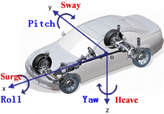
Fig. 2Single-track half car linear model
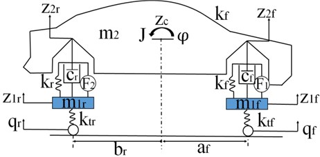
The general half-car suspension model is displayed in Fig. 2, which is a linear four-DOF system. It has a single sprung mass (car body) connected to two unsprung masses (front and rear wheels) at each corner. The sprung mass is free to heave and pitch, while the unsprung masses are free to bounce vertically with respect to the sprung mass. The passive suspensions between the sprung and unsprung mass are modeled as linear viscous dampers and spring elements, while the tires are modeled as simple spring elements. In the active suspension, two hydraulic actuators are utilized to connect the sprung mass and the unsprung masses to provide active forces. Active forces are inputs of active suspension systems.
According to Newton’s second law, the equations of motion are derived as follows. The motion equation of front body is given by:
For the rear body:
For the car body:
Moreover, the equation of motion for pitch motion (moment of balance) is written as Eq. (4):
From the half-car suspension system, the relationships among vertical displacements of the front sprung, rear sprung and vehicle body are expressed in Eqs. (5) to (8).
Eq. (5) expresses the front body:
Rear body is written by Eq. (6):
With small pitch angle assumption , the relationships among , and can be rewritten by Eq. (7) and (8).
For the front body we have in Eq. (7) as:
Rear body is expressed in Eq. (8) as:
In order to determine the vehicle pitch and heave motion, the two road surfaces are introduced, that is, sine road and white noise road, respectively. The sine road is expressed as:
where is the amplitude of road surface, , is the vehicle velocity, is the wavelength of road surface, is time.
The international organization for standardization (ISO) has a series of standards of road roughness classification using power spectral density (P.S.D) (ISO1982). The road displacement P.S.D is described in Eq. (10):
here, is the space frequency (m-1), is the reference space frequency, is the road displacement P.S.D, and are the coefficient of road roughness and the coefficient of linear fitting, respectively, where, . The road surface input model is created through an inform filter via Gaussian white noise and which is also applied in many presented studies [18-20]. It can be described as time domain mathematical modeling, expressed in Eq. (11) as:
where is power of road random, and are lower limit cutoff frequency of filter and Gaussian white noise, respectively.
Combing the vehicle model equations and the road input equations, the system model and the output equations in state space form is expressed by:
The state and the output variables are displayed by Eqs. (14) and (15):
The input variables are, respectively, written in Eqs. (16) and (17):
where:
3. Hydraulic actuator system
The hydraulic actuator consists of a hydraulic cylinder and an electrical spool valve. The force formula of linear electro-hydraulic actuator is represented by [21-23]:
where is the fluidic pressure constant. is valve coefficient, is the area of piston, is the coefficient of fluid leakage, is the volume, is the coefficient of volumetric elastic.
The spool valve displacement is written by:
where is the valve gain, is the servo amplifier gain, is the input voltage.
4. Controller design
The controller structure of active vehicle suspension consists of two loops shown in Fig. 3. The red dashed line is inner loop which is to track the desired force for the actual force. The green dashed line is the main loop which is to calculate the desired force signal. The dashed black color lines represent the mechanical signal. A fully benefit of this structure is that the inner loop can be directly used for the controller design of outer loop.
A hydraulic actuator is installed to connect the unsprung masses and the sprung mass. The PID controller is employed to the actuator in the inner control loop such that actuator can track its desired force. The details refer to paper [23]. It is assumed that the system does not have measurement noises and parameter uncertainties.
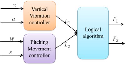
The control system is composed of two fuzzy controllers (the vertical vibration controller and the pitch motion controller) and one logic controller in this paper. As shown in Fig. 4, there are two inputs for vertical vibration controller and pitch movement controller, separately, then the two outputs from FLC act into one logic controller. The error vertical velocity and the change of error vertical acceleration server as the inputs in the vertical movement. The error pitch angle velocity and the change of error pitch angle acceleration are as the inputs in the pitch motion. The two output forces and , which are obtained from the fuzzy controller as intermediate variables, serve as the two inputs of logic controller.
Fig. 3Controller architecture
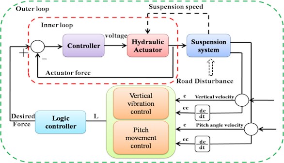
Fig. 4Block diagram of logic control system
4.1. Fuzzy logical control design
The control performance of a traditional controller greatly depends on an accuracy of a known system dynamic model, according to mathematical modeling. To meet practical requirements in an active suspension system, it is crucial to derive or to identify an appropriate model for the traditional controller design. Estimating uncertain effects are even more challenging due to the random noise occurred by road inputs. Hence, some model-free intelligent controllers were introduced to solve these problems, such as the FLC. The FLC is credited with being an adequate methodology for designing robust controllers, which is able to deliver satisfactory performance in the face of uncertainty and imprecision. As a result, the FLC has become a popular approach to nonlinear and uncertain system control in recent years. FLC is widely applied for a variety of challenging control applications since it is based on linguistic synthesis and inexact mathematical model as well as it provides a convenient method for constructing nonlinear controllers via the use of heuristic information. In other words, designing FLC is based on operator’s experience which acts as a human-in-the-loop controller. FLC was first introduced in the early 1970’s in an attempt to design controller for systems which are structurally difficult to create mathematical model owing to naturally existing nonlinearities and modeling complexities. The vehicle dynamics generally includes nonlinearities and uncertainties. Therefore, the FLC is proposed to cope with active suspension system in this study.
Fig. 5Block diagram of a typical fuzzy control system
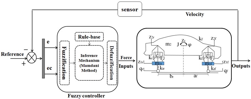
The active control of suspension is constructed based on FLC shown in Fig. 5. The FLC controller structure has two inputs and one output. The error of velocity (vertical velocity and pitch angle velocity) and change of the error (vertical acceleration and pitch angle acceleration) are utilized for producing a control output (moment).
FLC has three stages that are fuzzification, fuzzy inference and defuzzification. Fuzzification is to map variable from numerical values to linguistic variables. The triangular-shaped membership function is applied since they are quite basic and broadly employed. Five grades of linguistic variables are applied to the four inputs: vertical velocity, vertical acceleration, and pitch angle velocity and pitch angle acceleration. Negative large (NL), negative small (NS), NULL, positive small (PS), positive large (PL) lie in a scope of [–1-1]. The membership functions of positive, negative are introduced such that they cover large ranges of uncertainties.
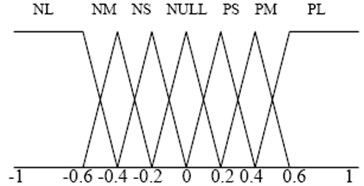
Defuzzification is scaled to real numbers from linguistic variables. The seven elements in the fuzzy sets of FLC outputs are employed for active suspension. The negative middle (NM) and positive middle (PM) are used as well such that the force can be precisely controlled. The employed membership functions of the FLC are triangular for the input and output variables, respectively, shown in Fig. 6 and Fig. 7.
Fig. 6Membership functions for the inputs (v,a,w,ε)
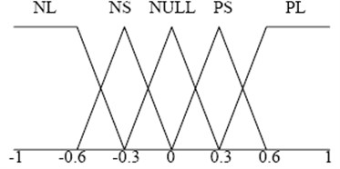
Fig. 7Membership functions for the outputs (L)
The relationship between inputs of the error and error-in-change is defined by the rule bases. The rules are expressed by if-then rules, which extract from fundamental knowledge and experience of the system and cover the input-output relations that define the control strategy. Based on the linguistic variables, the 25 fuzzy rules are defined based on the human experience. The rule-based of active suspension system is displayed in Table 1 (Bounce rule) and Table 2 (Pitch motion rule), which came from previous experience. A general form of the FLC rules can be defined as: IF and , Then .
The fuzzy inference generates the linguistic output variable with the rule base. A Mamadani method is applied in the fuzzy inference to defuzzificate outputs. A detailed analysis and description of the FLC for vehicle suspension systems can refer in [23-25]. In addition, stability of FLC is generally analyzed based on the traditional Lyapunov stability theory or extended Lyapunov theory. The details analysis of stability for the vehicle suspension systems can refer to the paper [6, 7].
Table 1Bounce rule bases
Intermediate variable | “Change-in-Error” EC | |||||
NL | NS | NULL | PS | PL | ||
“Error” | NL | PL | PL | PL | NS | NS |
NS | PL | PM | PS | NS | NM | |
NULL | PL | PS | NULL | NS | NL | |
PS | PM | PS | NS | NM | NL | |
PL | PS | PS | NL | NL | NL | |
Table 2Pitch rule bases
Intermediate variable | “Change-in-Error” EC | |||||
NL | NS | NULL | PS | PL | ||
“Error” | NL | PL | PL | PL | PS | NULL |
NS | PL | PM | PS | NULL | NS | |
NULL | PL | PS | NULL | NS | NL | |
PS | PS | NULL | NS | NM | NL | |
PL | NULL | NS | NL | NL | NL | |
4.2. Logic controller
Two types of motion are applied in this section. The first type is called translation motion (heave motion). The second one is called rotational motion (pitch motion). The input quantity force , can be obtained from logic controller in which the intermediate variables , serve as the inputs to the logic controller. It can be considered as the vibration motion of vehicle body is constructed by the resultant motion both translation along the vertical direction and rotational motion around C.G.
4.2.1. Translation motion
When a vehicle only does a translation motion, the forces from the front and the rear actuators are equal due to translation of vehicle body. The action of the front and the rear force actuators are shown in Fig. 8.
4.2.2. Rotational motion
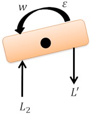
When a vehicle does pitch motion around C.G., in order to restrain the moment of inertia to reduce its pitch motion, there is an upward thrust force from the force actuator of the front suspension, while there must exist a downward drag force from the force actuator of the rear suspensions, shown in Fig. 9. For simplicity, it is assumed that the moments of thrust force and drag force are equal from front and rear suspension, respectively. By applying the analysis to both the translational motion and the rotational motion of the vehicle body, the equations of the intermediate variables and desired force are formulated as follows in Eqs. (20) to (22):
Fig. 8Action forces of vertical vibration
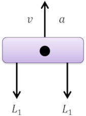
Fig. 9Action forces of pitching angle vibration
5. ADAMS full car model
The ADAMS program is multibody dynamic analysis software in automobile application. The full vehicle model is created based on the ADAMS/Car. Fig. 10 shows a full car model built in ADAMS/Car. The proposed full vehicle model in this paper consists of five subsystems: front suspension, rear suspension, steering, front tire and rear tire, where the front and the rear suspension models are, respectively, comprised of double wishbone model and parallel link suspension.
Fig. 10ADAMS 3D solid full car mode
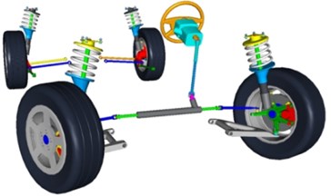
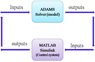
Fig. 11The principle of Co-simulation between ADAMS/Car and MATLAB
6. Results and discussion
To set up a co-simulation environment, ADAMS/Car provides two modules, ADAMS/Controls and ADAMS/Solver. The ADAMS/Controls module generates a simulation model based on the ADAMS/Car model, which can be imported into MALAB/Simulink. During a co-simulation, a closed loop between the ADAMS/Car model and control system is formed, as shown in Fig. 11. ADAMS/Car inputs of a model enter the ADAMS/Solver, which calculates the output signals from the model. The ADAMS/Solver output signals enter the control system, where MATLAB calculates the control signals, and a new iteration starts by sending the control signals and inputs to the ADAMS/Car model.
To investigate the effectiveness of the integrated control system based on FLC, a simulation mode with ADAMS/Car and MATLAB/Simulink is constructed based on the co-simulation. FLC control algorithms are added to ADMAS/Car model. The mass of vehicle, cornering stiffness, distance from center of gravity to the front and rear axles are defined. The vehicle speed and the road surface are set as well.
The full process using ADAMS/Car and MATLAB/Simulink was utilized as a control simulation environment. The parameters of vehicle model applied in the paper are given in Table 3 and these values are achieved from the ADAMS vehicle model as shown in Fig. 10. The driving speed is 50 km/h under white noise and sinusoid road surface.
Table 3Parameters used in vehicle mode
Parameters | Value | Unit | Parameters | Value | Unit |
53 | kg | 310000 | N⁄m | ||
117 | kg | 31000 | N⁄m | ||
663 | kg | 4165 | (N∙s)⁄m | ||
1067 | kg∙m2 | 4165 | (N∙s)⁄m | ||
58636 | N/m | 1.233 | m | ||
58636 | N/m | 1.327 | m |
6.1. White noise road surface
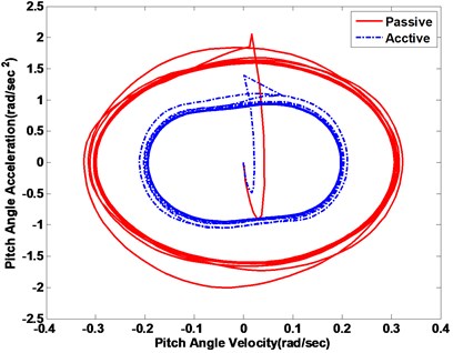
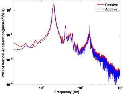
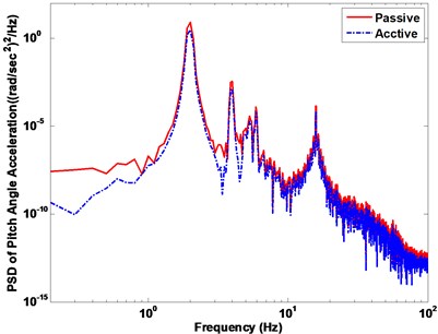
In the first subsection, the white noise road is employed to demonstrate the efficiency of controller strategy. The ride comfort performance is compared. The vertical and pitch displacement, vertical and pitch acceleration of the vehicle is used to evaluate ride comfort performance. The vehicle responses of the body acceleration and the pitch angle acceleration are compared with a passive suspension system. The vehicle vertical displacement and pitch angle are firstly represented in Fig. 12(a) and (b), respectively. The vehicle vertical acceleration and pitch angle acceleration under the disturbance of white noise road are displayed in Fig. 13(a) and (b), respectively. From the results of comparison, the active suspension has better performance to isolate road vibration. The Fig. 14 represents the phase plot vehicle body acceleration against vehicle velocity. The vertical motion is displayed in the Fig. 14(a), and Fig. 14(b) is shown the pitch motion. The FLC controller approaches obviously faster convergence with corroborates the fuzzy active suspension controllable steady state. Fig. 15 shows the vehicle body acceleration amplitude in frequency domain, in which the left of Fig. 15 is vertical motion, the right one is pitch motion. It gives that fuzzy active suspension can reduce at the key of resonance peak points between 100 and 101 Hz.
Fig. 12Vehicle displacement response with passive vs. active methods
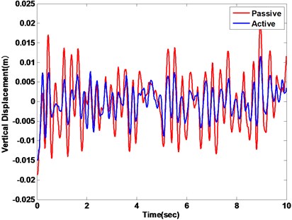
a) Vertical displacement
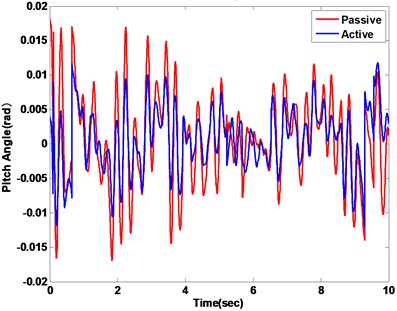
b) Pitch angle
Fig. 13Vehicle acceleration response with passive vs. active methods
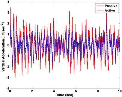
a) Vertical acceleration
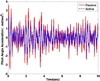
b) Pitch angle acceleration
Fig. 14Vehicle body response phase plot
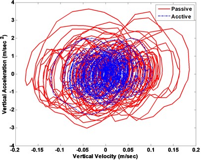
a)
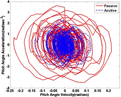
b)
Fig. 15Vehicle body acceleration response in frequency domain
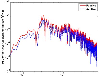
a) Vertical acceleration response
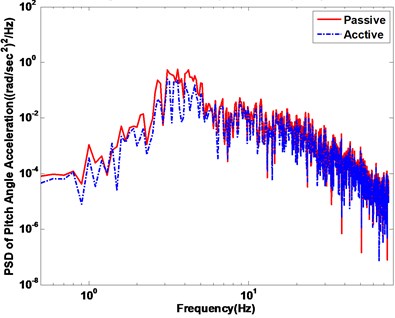
b) Pitch angle acceleration response
6.2. Sinusoid road surface
One of the input conditions, a sinusoid road input, is employed to excite the active suspension system. The vehicle vertical displacement and pitch angle are represented in Fig. 16(a) and (b), respectively. Under a sinusoid input, the responses of the vertical acceleration and the pitch angle acceleration are shown in Fig. 17.
Fig. 16Vehicle displacement response with passive vs. active methods
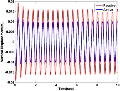
a) Vertical displacement
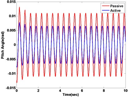
b) Pitch angle
Fig. 17Vehicle acceleration response with passive vs. active methods
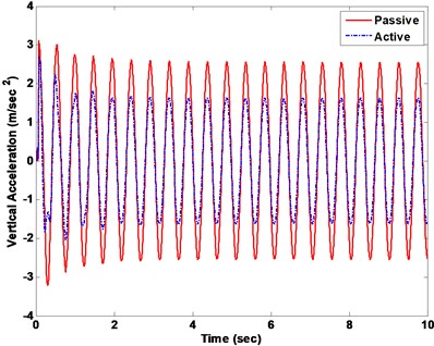
a) Vertical acceleration
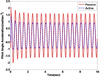
b) Pitch angle acceleration
Fig. 18Vehicle body response phase plot
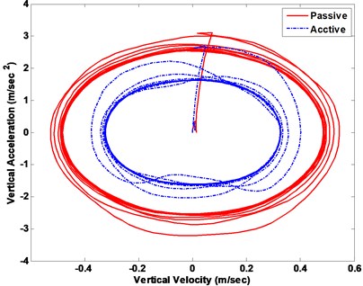
a)
b)
The phase plot displays the active fuzzy suspension can quickly converge in Fig. 18. The Fig. 19 displays the vehicle acceleration amplitude in frequency domain under the sinusoid road surface. It also indicates that the fuzzy active suspension can reduce the key resonance peak points between the 100 nd 101 Hz both the vertical motion and pitch motion. If it is exposed to ride vibrations around 9 Hz for 6-7 hours, a vehicle driver or passengers will feel a general sense of discomfort such as lower jaw symptoms, abdominal pains, need to urinate and continuous muscle contraction etc.
As before the graphs were inconclusive, the RMS values of the responses were presented shown in Fig. 20. From these figures, it can be manifested that FLC has an attractive benefits in isolating vibration from road compared with passive vehicle suspension, when the vehicle drives at the white noise and the sinusoid road conditions.
Fig. 19Vehicle body acceleration response in frequency domain
a) Vertical acceleration response
b) Pitch angle acceleration response
Fig. 20RSM acceleration of heave and pitch motion
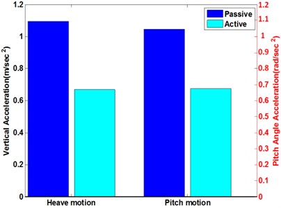
a) White noise road surface
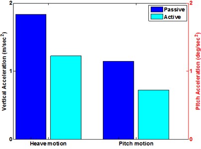
b) Sine road surface
7. Conclusions
In this paper, we have developed a combined simulation scheme for fuzzy logic control of half car suspensions to improve ride comfort of passengers based on the heave and the pitch motion. The FLC which introduces the body acceleration and suspension travel velocity as inputs and selects forces as outputs to control suspension system is feasible. And the four DOF half car model and decoupling transformations are introduced for simplicity in designing the controller. A multi-DOF nonlinear model, constructed in ADAMS/Car, is co-simulated by ADAMS/Car and MATLAB/Simulink to prove the effectiveness of the controller. It is demonstrated that our proposed active suspension design shows a good performance to minimize the heave and the pitch angle accelerations. It has been shown that the performance of ride comfort based on FLC is better than that of the passive suspension under roughness road conditions. Therefore, it has been illustrated that the controller we have designed can provide passengers’ comfort by achieving a better performance in rough road conditions.
References
-
Rasmussen G. Human body vibration exposure and its measurement. Journal of the Acoustical Society of America, Vol. 73, Issue 6, 1983, p. 2229-2250.
-
Hulshof C., Zanten B. V. Whole-body vibration and low-back pain. International Archives of Occupational and Environmental Health, Vol. 59, Issue 3, 1987, p. 205-220.
-
Reimpell J., Stool H. The Automotive Chassis: Engineering Principles. Arnold, 1998.
-
Suspension Vehicle. Wikipedia, 2008.
-
ISO 2631-1 Mechanical Vibration and Shock-Evaluation Human Exposure to Whole-Body Vibration Part I: General Requirements.
-
Chen L., Zhou, L. K., Jiang H. B., Wang R. C., Zhou K. K. Control system design and stability analysis of semi-active suspension based on fuzzy dynamic model. Journal of Mechanical Engineering, Vol. 44, Issue 2, 2008, p. 113-117.
-
Pang H., Fu W. Q., Liu K. Stability analysis and fuzzy smith compensation control for semi-active suspension systems with time delay. Journal of Intelligent and Fuzzy Systems, Vol. 29, Issue 6, 2015, p. 2513-2525.
-
Celnikeer G. W., Gedrick J. K. Rail vehicle active suspensions for lateral ride and stability improvement. ASME Journal of Dynamic Systems Measurement and Control, 1982, p. 101-106.
-
Alleyne A., Hedrick J. K. Nonlinear adaptive control of active suspension. IEEE Transactions on Control Systems Technology, Vol. 3, Issue 1, 1995, p. 94-101.
-
Ekoru J. E. D., Dahunsi O. A., Pedro J. O. PID control of a nonlinear half-car active suspension system via force feedback. AFRICON Conference, 2011, p. 1-6.
-
Kashtiban A. M., Pourqorban N., Alizadeh G., Hasanzadeh I. Nonlinear optimal control of a half car active suspension. International Conference on Computer and Electrical Engineering, 2009, p. 460-464.
-
Yahaya M. S., Johari H. S. B. O. Modeling and control of the active suspension system using proportional integral sliding mode approach. Asian Journal of Control, Vol. 7, 2005, p. 91-98.
-
Eimadany M. M., Bassam B. A. A., Fayed A. A. Preview control of slow-active suspension systems. Journal of Vibration and Control, Vol. 17, Issue 2, 2011, p. 245-258.
-
Yagiz N., Hacioglu Y., Taskin Y. Fuzzy sliding-mode control of active suspensions. IEEE Transactions on Industrial Electronics, 2008, p. 3883-3890.
-
Karnopp D. Passive and active control of road vehicle heave and pitch motion. IFAC 10th Triennial World Congress, 1987, p. 183-188.
-
Wong J. Y. Theory of Ground Vehicles. John Wiley and Sons, New York, 1978.
-
ADAMS/Car User’s Guides. Mechanical Dynamics Inc., USA, 2002.
-
Taghirad H., Esmailzadeh E. Automobile passenger comfort assured through LQG/LQR active suspension. Journal of Vibration and Control, Vol. 4, Issue 5, 1998, p. 603-618.
-
Crolla D., Yu F. Vehicle Dynamics and Control. China Communications Press, Beijing, China, 2004.
-
Uys P. E., Els P. S., Thoresson M. Suspension settings for optimal ride comfort of off-road vehicles traveling on roads with different roughness and speeds. Journal of Terramechanics, Vol. 44, Issue 2, 2007, p. 163-175.
-
Xuan D. J., Kim J. W., Nan Y. H., Kim Y. B. Time delay force control for vehicle active suspension system. Proceedings of the 26thChinese Control Conference, 2007, p. 640-645.
-
Kim J. W., Xuan D. J., Nan Y. H., Kim Y. B. A quantitative feedback control system design for the multi-axis simulator having uncertain plants. International Journal of Modeling, Identification and Control, Vol. 12, Issue 3, 2011, p. 280-289.
-
Nan Y. H., Deng C., Shi W. Comparison of the ride performance of an integrated suspension model. Journal of Vibroengineering, Vol. 16, Issue 8, 2014, p. 3699-3711.
-
Li Q., Yoshimurma T., Hino J. Active suspension with preview of large-sized buses using fuzzy reasoning. International Journal of Vehicle Design, Vol. 19, Issue 2, 1998, p. 187-198.
-
Chou J. H., Chen S. H., Lee F. Z. Grey-fuzzy control for active suspension design. International Journal of Vehicle Design, Vol. 19, Issue 1, 1998, p. 65-77.
About this article

