Abstract
The development of simulated training system (simulator) for container crane has made some progress; however, there are still problems in insufficient training function (e.g. the container spreader alignment skill training, one of the most important skill in conventional terminals) and lack of dynamic sense of immersion. In this paper, the technical status of container crane simulator is summarized and the state of art of dynamics model and its solution algorithm for container crane is reviewed. It is pointed out that establishing an accurate real-time simulation dynamics model and studying an efficient algorithm under certain calculation accuracy is the key problem of enhancing immersion, reality and training effect of the simulator. With reasonable simplification and hypothesis, the dynamic equilibrium equations of the trolley-hoisting system are established, further considering the characteristics of the mechanical and electrical transmission system of the crane and also the external mean wind load. Based on the four order Runge-Kutta method by MATLAB programming, the fast solution to the two order ordinary differential equations is realized on personal computer, and the three dimensional (3D) space swing time-history response of the container spreader can be obtained in real-time. The results of numerical calculation are consistent with the actual situation, thus, this study provides a feasible technical route for the real-time dynamics simulation in the container crane simulated training system.
1. Introduction
Simulated training system (simulator) is a kind of virtual reality (VR) system which integrates many technologies such as system dynamics simulation technology, 3D real-time visual simulation technology, sensor and control technology, multimedia and network technology, etc. [1]. Compared with the field training, it has the advantages of good safety, good economic performance, wide application range, good training effect, and the site is not limited [2]. In recent years, simulators have been rapid developed, and used in the fields of aircraft, ships, cars, trains, subway, port machinery (like container crane, as shown in Fig. 1) and other engineering machinery and vehicles [1-3].
However, if the visual, tactile and auditory simulation effects of the VR system is not consistent with actual operation, the trainee is easy to master wrong operating skills and experience, which will endanger future practical operation [4]. Due to this shortcoming, many simulators don’t have satisfactory training effect. Therefore, it is an urgent problem to enhance the simulation effect of the simulator, improve the system's immersion sense, and improve the practical training function.
Since the 1980s, Holland BOS/CAT company, USA Globalsim company and Ship Analytics MPRI company, Norway Hitec-O company, British TSI company, South Korea TSB company, Canadian Simlog company have carried out the relevant research and development work on crane simulator [5]. Among them, the MasterLiftTM ML4000 type crane simulator of the Globalsim company (as shown in Fig. 2) is one of the representatives. It’s hardware consists of an integrated control platform for many types of cranes, a teacher console, a multi degree of freedom (MDOF) excitation platform, a dome visual projection system and a realistic sound system. The visual simulation effect of the simulator looks realistic, the mixed audio is a live recording, making a strong sense of immersion [6]. The disadvantage of this simulator is that the MDOF excitation platform can only provide trainee the body feeling of motion inertia; it cannot simulate the vibration body feeling during driving in real-time.
Fig. 1The container crane in Shanghai Maritime University
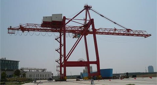
Fig. 2GlobalSim company’s ML4000 type crane simulator of MasterLiftTM series
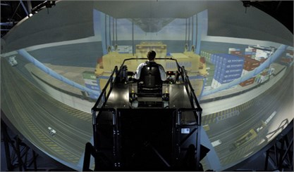
a) System panorama
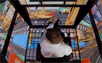
b) Visual simulation screen
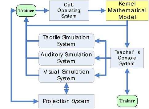
At present, in the “Along the Way” national strategy, China’s port and its equipment industry is recovering [7]. And container crane simulator has a long R&D history and practical needs in China. Shanghai Maritime University [8, 9], Water Transport Science Research Institute of Ministry of Transportation [5], Wuhan University of Technology [10], Dalian Maritime University [11], etc. have been researching container crane simulator since late 1990s. Typically, the system architecture of the simulator is shown in Fig. 3 [12].
The current status and characteristics of technology can be summarized as follows. In simulation model and solution method, the trolley – pendulum dynamic model [8, 10] was widely adopted, based on the principles of theoretical mechanics; According to the mechanical transmission theory, the transmission equations of the gantry travelling, the trolley travelling and the hoisting mechanism were deduced; Then using explicit numerical integration algorithm combined with predictor-corrector formula to calculate dynamic response. In the aspect of visual simulation, the real-time visual model was mainly established by MultiGen Creator software, and Vega or OpenGVS for graphics driven by the pre-calculated dynamic response data. In the aspect of tactile feeling simulation, Jiang et al. [9] made a beneficial attempt, where a single degree of freedom (SDOF) driver seat vibration simulation system was designed by using the servo motor and electric cylinder, which can generate the gantry or trolley travelling vibration. In the aspect of auditory simulation, basically it was recorded on site and then played back with the visual scene.
Obviously, the R&D of container crane simulator has made a lot of progress, especially the visual simulation can produce a good sense of immersion. While there are still shortcomings such as insufficient training function, poor training effect and lack of dynamic sense of immersion, specifically speaking: 1) The simulated motion is too simple to complete the training of key operations of controlling trolley and container spreader (e.g. the container spreader alignment skill training, one of the most important skill in conventional terminals) for the drivers. 2) There is still difficulty in adequately simulating driving body feeling of system vibration, and with poor coordination of simulated motion in visual scene.
To sum up, improving the kernel mathematical model of the simulator, i.e. establishing an accurate dynamics model for real-time simulation and studying an efficient algorithm under certain calculation accuracy is the key issue of achieving subsystems’ simulation synchronization, will enhance immersion, reality and training effect of the simulator.
Fig. 3System architecture of the simulator
2. The state of art of recent research
2.1. Dynamics simulation of container crane
The main function of container crane is to complete the loading and unloading of containers between ship and terminal, through the cooperative work of the metal structure and the mechanism or subsystem arranged on it, such as hoisting mechanism, gantry/trolley travelling mechanism, hoisting mechanism, power system, control system and safety subsidiary system, etc. The dynamics simulation of container crane mainly studies dynamic response and characteristics of the structure or mechanism under the operating conditions of trolley travelling, gantry travelling and also external environmental excitations.
Container crane (bridge crane) is a huge and complex structure and an integrated equipment, coupled with multi-physics domain of mechanical, electrical, control and other disciplines. It is a hot research point of port machinery dynamics simulation [13, 14]. Niu, Ouyang et al. [15] put forward a comprehensive dynamic model for the whole system of electric cranes, including the steel structure, the mechanisms, the induction motors, and their drive systems, which could simulate the steady and transient state characteristics of the crane during various operations. Electromechanical coupled system dynamics equations of the electric crane under the conditions of loading and unloading were established, based on the transient model of three phase induction motor by the application of Hamilton Principle. The effects of the tensional stiffness of the floating shaft in the high speed link of the hoisting mechanism and rotor resistance of the driving motor on dynamic responses of the system were numerical simulated and discussed [16]. Recently, in order to improve the accuracy and stability of dynamic response calculation and motion control, the nonlinear characteristics [17] of the system were considered, while it is more difficult to achieve real-time computation.
Container crane is a kind of expensive port manned equipment, with a large high-rise flexible structure, which is vulnerable to typhoons, earthquakes and other disasters. Therefore, the crane safety under the external load (wind and earthquake) of the environment is one of the main topics of dynamic simulation (or experimental) analysis [14, 18, 19]. In addition, the structural coupled vibration characteristics analysis is another important content of the crane dynamic simulation. At present, there are not so many research reports on the structural coupled vibration of the container crane and other port machinery equipment. Lu et al. [20, 21] studied the problem systematically: 1) Further developed coupled vibration theory for container hoisting equipment, and introduced a miniature scale model experiment to verify the theoretical method’s validity and reliability; 2) The container trolley (i.e. moving load) and truss bridge (i.e. structure) coupled vibration time-domain responses, inspired by stochastic self-excitation including track irregularity and hunting movement as well as environmental (wind and seismic) load, were quickly obtained by using free-interface component mode synthesis (CMS) method [20]; 3) A new technique of dual-compatibilities free-interface component mode synthesis (CMS) was derived by transforming link substructure into super element with Guyan static condensation. The new CMS technique has high calculation accuracy, can efficiently reduce degree of freedom (DOF) of the system, thus, it has a widespread application prospect in dynamic analysis of the structures containing nonlinear link components such as Lead Rubber Bearing (LRB), nonlinear spring, etc. [21]. But the computing time of above analysis is in minute or in hour, still far away from meeting the requirement of real-time simulation.
2.2. Real-time dynamics simulation of container crane simulator
The dynamics model of crane is the basis for calculating dynamic characteristics or response of the system. The key issue of real-time simulation is to improve the efficiency of calculation in the premise of ensuring the accuracy. However, the accuracy and efficiency of calculation is a natural contradiction. In spite of much progress in the dynamic simulation of container crane [12-21], the real-time dynamic simulation for container crane simulator is still to be studied.
Currently, real-time simulation technology is mainly applied to virtual construction or virtual installation [22]. Rapid and accurate motion planning of cranes directly affects the safety and productivity of operations. AlBahnassi et al. [23] developed a system framework and software modules of the crane 3D motion planning visual real-time simulation system. Hung et al. [24] proposed a configurable model which is reusable, fast-prototyping, and extendable to support real-time visualization of the various erection processes with different cranes and configurations. The developed model of the crane was divided into three modules which can be reconfigured for different erection tasks. Each module was defined using multiple rigid bodies and the joint constraints of multi-body dynamics. The proposed modeling method can also be easily adapted to existing physics engines, thus can improve the efficiency of visualization modeling. Strictly speaking, these real-time simulations are still in kinematics, still cannot be regarded as system dynamics.
In the aspect of real-time dynamics simulation, Taichi [25] established the 6DOFs trolley multi-body dynamics model for crane simulator and achieved the prediction of dynamic system performance and comfort evaluation. The real time solution results were calculated by the approximate analysis method, in the process of trolley travelling simulation with a total 91DOFs system. In this case, the real time solution was obtained by using 2 ms as numerical integration time step. Kang et al. [22] developed a mathematical model to support the simulation and visualization of cranes, composed of two sub-models, i.e. a kinematics model and a dynamic model. The kinematics model was to present the crane components controlled by the operators. The dynamic model was to present the dynamic behavior in suspended system (including the cable and rigging object), which cannot be controlled directly by the operators. A computer program that simulates and visualizes detailed crane activities was developed to verify the feasibility of these methods. Based on the trolley – pendulum dynamic model [8, 10], according to the mechanical transmission theory, the transmission equations of the gantry, the trolley and the hoisting mechanism were deduced. The system dynamic equations were established, then using explicit numerical integration algorithm combined with predictor-corrector formula to calculate the dynamic response.
The existing models [8, 10, 22, 25], for the sake of real-time dynamics simulation, are overly simplified. The system DOFs number are too small, and the structural deformation and vibration as well as interaction between mechanisms are ignored, not to mention the wind load and other external excitations. Therefore, the simplified model is unable to accurately reflect the starting and braking dynamics characteristics of the structure or mechanism, coupled vibration characteristics during travelling operations, twist characteristics of the container spreader-steel wire rope system, and so on. This is the root cause to the problems of insufficient key skills training function and lack of dynamic sense of immersion.
In summary, computational multi-body dynamics is currently an effective way to rapid calculating system dynamic characteristics and responses [26]. Multi-body dynamic model as well as the simplified mechanical model, compared with the real system or the finite element model, can greatly reduce the DOFs of the system and improve the calculation efficiency. Thus, general and special multi-body dynamics software are emerging constantly [27], like ADAMS, DADS, SIMPACK, Working Model, Recurdyn, CADAMB and so on [28]. Although these software or program [29] can obtain system dynamic characteristics or response accurately through the modeling and calculation, only the offline calculation result data is able to be exchanged with visual simulation system, so it’s not easy to do real-time interactive simulation. Therefore, feasible ways to real-time dynamics simulation of crane simulator include: 1) establishing a systemic multi-body dynamic model as the kernel mathematical model or 2) developing specialized software which can do real-time interaction with visual simulation system. Obviously, the former is more easy to be realized. On the basis of existing work and current technology analysis of container crane simulator, further considering the characteristics of the mechanical and electrical transmission system of the crane and also the external wind load, this study will focus on real-time simulation dynamics model and rapid solution algorithm for the trolley-hoisting system.
3. The dynamic equilibrium equations of the trolley-hoisting system
3.1. The establishment of 3D swing model of the trolley-hoisting system
As mentioned above, container crane is a complex system. To simplify the analysis, the following assumptions are made: 1) Ignore the stiffness and mass of the hoisting wire rope (relative to the spreader and container it is very small); 2) The container and spreader is regarded as a particle, the rotation and twist of container and the interaction between container and spreader are not taken into account; 3) Without considering the influence of coupled vibration of the trolley and boom. Besides, in the hoisting operation process, the gantry travelling mechanism is at rest.
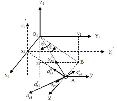
Based on the above assumptions, the simplified 3D swing model of the trolley-hoisting system at a certain moment during hoisting operation is established, as shown in Fig. 4. In Fig. 4, the moving particle represents the lifting container and spreader, and the reference systems are chosen as follows: 1) Ground fixed coordinate system (): the left rear wheel of the gantry and the ground contact point when the scene is initialized is the origin of the coordinate. axis is perpendicular to the coast line to the sea side, axis is vertical upward, axis is determined by the right-hand rule. The movement state of the crane system is determined by the coordinates of the trolley’s center point and the coordinates of the spreader’s center point (, , ) in coordinate system , where, indicates the displacement of the trolley relative to the gantry, indicates absolute displacement of the gantry. 2) Movable reference system is fixed to gantry. (In this study, the gantry travelling is stationary). 3) Movable reference system () fixed to trolley: the origin is fixed at the center of the trolley, and the three axes are parallel to the three axis of , with the same directions. In , Plane , composed of steel wire rope , axis and steel wire rope’s projection on Plane , is marked as Plane . The line is perpendicular to and through the origin. Plane is composed of and . Plane is parallel to Plane and through . The angle between and is . The angle between and is . 4) Movable reference system is fixed to . 5) Movable reference system is fixed to .
Fig. 4The simplified 3D swing model of the trolley-hoisting system
The coordinates of in the coordinate system is . From Fig. 4, we know:
According to coordinate transformation, the coordinates of in ground fixed coordinate system is (, , ), as below:
Point is the projection of in Plane . The projection length of hoisting steel wire rope in is:
The tension of wire rope is , then the projection of the on the three axis are respectively: , , .
and are translational coordinate systems, while and are rotating coordinate systems. Through acceleration synthesis, it obtains:
where, , Point is to do linear motion along the wire rope relative to ; Acceleration component of in is , along axis; Acceleration component of in is , along axis; Acceleration component of in is , , , ; Acceleration component of in is , , , .
3.2. Resistance calculation
3.2.1. The wind resistance on the container and spreader
The wind resistance is related to vertical wind area perpendicular to the wind direction and the wind pressure. The component of wind resistance in the axis and axis direction is respectively and . According to Crane Design Code (GB/T 3811-2008):
where, indicates wind coefficient; indicates the wind pressure height coefficient; is calculation wind pressure along axis, , is the wind speed component along axis; is windward area perpendicular to the axis, indicates the length of container, indicates the height of container (the wind load is mainly on the container).
Similarly, the wind resistance force in the direction of axis:
where, is the width of container; is the wind speed component along axis; the remaining symbols are the same meaning as above.
Decompose lifting weight into component perpendicular to the projection direction of wire rope and component along the projection direction of wire rope. Also decompose the inertia force and wind resistance on the lifting weight into , , and , .
3.2.2. Trolley running resistance
Trolley running resistance consists of frictional resistance and wind resistance . includes friction of wheel rolling, friction of wheel bearings, and additional friction caused by the hunting moment. Due to the additional frictional is difficult to be accurately calculated, it is usually considered by multiplying the sum of frictions of wheel rolling and bearings by the additional coefficient. Thus:
where, is wheel pressure, ; is wheel diameter; is rolling friction coefficient of wheel; is wheel bearing friction coefficient, take the value of 0.1; is wheel bearing inner diameter; is additional coefficient of trolley travelling, take the value of 1.5.
Make , then =.
With the same method in Section 3.2, the wind resistance of trolley travelling can be obtained:
Thus:
3.2.3. Gantry running resistance
Gantry running resistance:
where, is pressure on one wheel set of gantry travelling, , is lifting weight, is trolley weight, is gantry weight; is wheel diameter; is rolling friction coefficient of gantry wheel; is gantry wheel bearing friction coefficient, take the value of 0.1; is gantry wheel bearing inner diameter; is additional coefficient of gantry travelling, take the value of 1.5.
Make , , then .
3.3. Transmission equations
3.3.1. Hoisting mechanism transmission equation
During hoisting operation, the hoisting motor drive torque is . The hoisting mechanism is simplified to be a single shaft output system, then the converted load torque:
where, indicates the hoisting drum radius; indicates the transmission ratio of hoisting mechanism; indicates the transmission efficiency of hoisting mechanism.
The converted flywheel moment of the hoisting mechanism:
where, 0.2; is the flywheel torque of the hoisting motor itself.
Because , and , hoisting motor angular acceleration:
where, indicates hoisting motor speed; indicates rotation angle of the hoisting drum; is hoisting speed.
According to the mechanical characteristics of the motor:
where, is output torque of the motor; is characteristic curve slope of the hoisting motor; is idle speed of the hoisting motor without loading.
From:
The transmission equation of the hoisting mechanism can be obtained:
3.3.2. Trolley travelling mechanism transmission equation
On the drive chain of trolley travelling mechanism, use the same method of hoisting mechanism, the converted load torque:
where, is resistance force the trolley travelling subjected, indicates trolley travelling speed; indicates trolley travelling motor speed; indicates transmission efficiency of trolley travelling mechanism.
Because , , then:
where, is trolley wheel speed; is trolley wheel radius; is trolley travelling transmission ratio; the converted flywheel moment , is the flywheel torque of the trolley travelling motor itself.
According to the mechanical characteristics of the motor:
And the trolley travelling mechanism transmission equation can be obtained:
3.3.3. Gantry travelling mechanism transmission equation
The gantry travelling mechanism transmission equation is similar to the trolley’s. The converted load torque:
where, is resistance force the gantry travelling subjected; indicates gantry travelling speed; indicates gantry travelling motor speed; indicates transmission efficiency of gantry travelling mechanism.
Because , and , then:
where, is trolley wheel speed; is gantry wheel radius; is gantry travelling transmission ratio; the converted flywheel moment:
and is the flywheel torque of the gantry travelling motor itself.
According to the mechanical characteristics of the motor:
The trolley travelling mechanism transmission equation can be obtained as below:
3.4. Equilibrium equations
According to the D’Alembert’s principle, list the lifting weight’s dynamic equilibrium equation along and perpendicular to the wire rope direction in and perpendicular to the projection direction of wire rope in as follows:
By Eq. (28), the wire rope tension can be obtained:
Substitution Eq. (31) into Eq. (16) and Eq. (21), we have:
Thus, the dynamic equilibrium equations of the trolley-hoisting system in the state space can be got:
4. Solution of system dynamics equations
4.1. Numerical solution method
When the equation derivative and initial value information is known, Runge-Kutta method can eliminate the process of complex computation for solving differential equations. The classical four order Runge-Kutta algorithm is as follows:
Recursion formula:
where, indicates the slope on initial moment of the computational time step, ; indicates the slope on the middle time of the computational time step, it is determined by with Euler method, ; is also the slope on the middle time, it is determined by , ; indicates the slope on end moment, it is determined by , . Each sub step calculation error is of order, the total accumulated error of order.
4.2. Dynamics equation order reduction
The Eq. (34) can be expressed as the following form of standard two order ordinary differential equations:
Make , , , , , , , , , , the Eq. (37) can be transformed into an equivalent first order ordinary differential equation as below:
Eq. (38) can be quickly solved by four order Runge-Kutta method.
5. Case study
5.1. Main parameters
Taking a certain type of 40 ft container crane as the analysis object, the basic performance parameters of the crane are listed in Table 1.
According to Table 1 and relevant data, the main parameters of the dynamics equation in the MATLAB program are shown in Table 2.
Table 1Basic performance parameters of the 40 ft container crane
Item | Parameter | Item | Parameter | ||||
Rated load weight | Under spreader | 45 T | Motor | Gantry travel | 16×11 KW, 1750 rpm | ||
Speed | Main hoist | 40 T load | 60 m/min | Boom pitching | 1×95 KW, 1750 rpm | ||
Unload | 120 m/min | Gauge | 26 m | ||||
Trolley travel | 150 m/min | Front / Rear extension | 36 m / 12 m | ||||
Gantry travel | 45 m/min | Lifting altitude | Above track | 27 m | |||
Boom hoisting time | 5 min | Total height | 42 m | ||||
Motor | Main hoist | 2×260 KW, 900/1800 rpm | Power source | Generator | Main generator | 1625 KW | |
Trolley travel | 2×75 KW, 1750 rpm | Vice generator | 256 KW | ||||
5.2. Results analysis and discussion
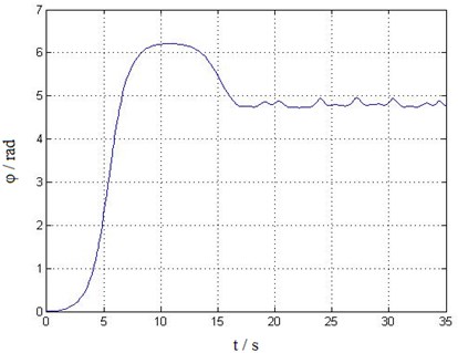
The swing angles of lifting weight were solved by MATLAB V2008 in DELL Precision 4600 (Intel 2.5 GHz, 8 GB DDR3 Memory). The average calculating time is 1.836 ms. The obtained swing angle and angular velocity dynamic responses versus time are shown in Figs. 5-8.
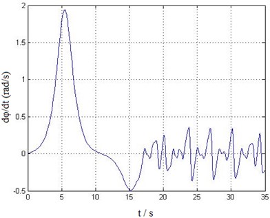
It can be seen from Figs. 5-8, the balance position of the lifting weight swing is not at the zero point, that’s because when considering trolley travelling movement and introducing transmission characteristics of various mechanisms and external wind load excitation, there exists of non-equilibrium and nonlinear in the system. This also leads to a complex transient response in the former 16 s of time history curve shown in Figs. 5-8. After 16 s, the responses gradually become steady, showing a more obvious periodic motion trend. The dynamic response results are in accordance with the actual situation, thus, it can be concluded that the established trolley-hoisting system dynamic model and the fast (near real time) solving method is correct and effective.
Table 2Main parameters’ value in the dynamics equation
Parameter | Value/Unit (Note) | Parameter | Value/Unit (Note) |
Lifting weight, m | 25813 kg (40 ft container gross weight 22000 kg, spreader weight 3813 kg) | Wind speed along axis | 20 m/s |
Hoisting drum radius | 450 mm | Trolley travelling wheel radius | 340 mm |
Hoisting mechanism transmission ratio | 31.5 | Trolley travelling mechanism transmission ratio | 39 |
Hoisting mechanism transmission efficiency | 75 % | Trolley travelling mechanism transmission efficiency | 75 % |
Characteristic curve slope of the hoisting motor | 64.58 (Motor Type YZP355M-6) | Characteristic curve slope of the trolley travelling motor | 28.5 (Motor Type YZP280M-4) |
Idle speed of the hoisting motor without loading | 1480 rpm | Idle speed of the trolley travelling motor without loading | 1480 rpm |
Flywheel torque of the hoisting motor | 225.4 Nm2 | Flywheel torque of the trolley travelling motor | 57.23 Nm2 |
Fig. 5Swing angle θ time history curve
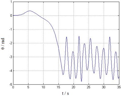
Fig. 6Swing angle φ time history curve
However, this paper aims to study real-time simulation dynamics model and solution algorithm for the trolley-hoisting system, the coupled vibration of trolley and structure as well as track irregularity and fluctuating wind load etc. random excitations are not considered in the model, therefore, there are only low frequency harmonic components in the steady responses. On the other side, the established trolley-hoisting swing model is still not able to reflect the twist and interaction between the container and steel wire ropes. The simulated dynamic response time history curves are in agreement with measured results only in general trend. The further research could be on the premise of real-time computing, to establish more accurate multi-body and multi-DOFs trolley-hoisting dynamic model, which can reflect the coupled vibration of trolley and structure under random self-excitation, and the twisting characteristics of steel wire rope, etc.
Fig. 7The angular velocity time history curve of swing angle θ
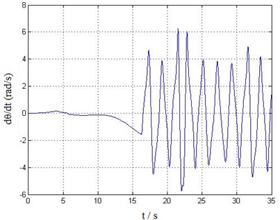
Fig. 8The angular velocity time history curve of swing angle φ
6. Conclusion
The reason why current simulated training system for container crane has problems of insufficient training function and lack of dynamic sense of immersion has been analyzed in this study. Establishing an accurate real-time simulation dynamics model and studying an efficient algorithm under certain calculation accuracy is the key issue. However, currently, on the one hand, the crane dynamics models which aims to study system dynamic response under self-excitation or external excitations are so accurate and complex that the computation time is in minute or in hour, cannot meet the requirement of real-time simulation. On the other hand, most real-time simulations for crane simulator are still in kinematics. Or the existing dynamics models are so simplified that are unable to accurately reflect the trolley-hoisting system’s dynamic responses.
To solve this contradiction, firstly, the 3D dynamics model of the trolley-hoisting system is established, then the transmission equations of the hoisting, trolley travelling, gantry travelling mechanisms are derived. The wind resistance and running resistance on the trolley and container are calculated, and then the dynamic equilibrium equations of the trolley-hoisting system are obtained, further considering internal transmission characteristics and external wind load. Through reducing the second order ordinary differential equations to a first-order one, based on the Runge-Kutta method, the quick solution to the equations is realized by MATLAB programming on personal computer, obtaining the lifting weight swing response at real-time.
The results of the simulated dynamic response time history curves are in good agreement with the actual situation, which proves that the proposed modeling method and solution algorithm provide feasible technical route to real-time dynamics simulation for the container crane simulator.
References
-
Wilson B. H., Mourant R. R., Li M., et al. A virtual environment for training overhead crane operators: real-time implementation. IIE Transactions, Vol. 30, Issue 4, 1998, p. 589-595.
-
Rouvinen A., Lehtinen T., Korkealaakso P. Container gantry crane simulator for operator training. Proceedings of the Institution of Mechanical Engineers Part K – Journal of Multi-Body Dynamics, Vol. 219, Issue 4, 2005, p. 325-336.
-
Dong Haoming, Xu Guifang, Chen Dingfang Research on overhead crane training system and its construction based on virtual reality. Proceedings – International Conference on Artificial Intelligence and Education, 2010, p. 206-209.
-
Juang J. R., Hung W. H., Kang S. C. SimCrane3D(+): A crane simulator with kinesthetic and stereoscopic vision. Advanced Engineering Informatics, Vol. 27, Issue 4, 2013, p. 506-518.
-
Liu Jin-chuan, Cheng Xin-feng, Rao Jing-chuan The development review of port crane training simulator. Hoisting and Conveying Machinery, Vol. 8, 2006, p. 1-5, (in Chinese).
-
Terminal Handling. New Crane Training Simulator for Shanghai Maritime University. International Port Technology [EB/OL]. http://www.porttechnology.org/news/new_crane_training_simulator_for _shanghai_maritime_university, 2009.
-
Jia Da-shan 2014’ review and 2015’ outlook of coastal port development. China Port, Vol. 1, 2015, p. 6-12, (in Chinese).
-
Wang Chong-hua, Liang Gang, Liang Cheng-ji The Training Simulator of Container Crane. Journal of System Simulation, Vol. 14, Issue 7, 2002, p. 904-921, (in Chinese).
-
Jiang Xiao-gang, Mi Wei-jian Design of chair’s vibration prompting system based on training simulator. Chinese Journal of Construction Machinery, Vol. 2, Issue 3, 2004, p. 319-323, (in Chinese).
-
Liu Gang, Dong Ming-wang, Wang Shao-mei A real time simulation of partial pendulum in a container crane driving simulator. Port Operation, Vol. 142, Issue 2, 2002, p. 8-10, (in Chinese).
-
Lin Jin-yao, Yin Yong, Jin Yi-cheng, et al. Equation of motion and prototype machine of container crane loading simulator system. Journal of System Simulation, Vol. 16, Issue 5, 2004, p. 931-939, (in Chinese).
-
Lu Kai-liang, Huang You-fang, Yan Wei, et al. Joint simulation of trolley vehicle-frame structure coupled vibration using ADAMS and ANSYS for container crane simulated training system. International Journal of Hybrid Information Technology, Vol. 5, Issue 5, 2013, p. 197-208.
-
Abdel-Rahman E. M., Nayfeh A. H., Masoud Z. N. Dynamics and control of cranes: a review. Journal of Vibration and Control, Vol. 9, Issue 7, 2003, p. 863-908.
-
Arena A., Casalotti A., Lacarbonara W., et al. Dynamics of container cranes: three-dimensional modeling, full-scale experiments, and identification. International Journal of Mechanical Sciences, Vol. 93, 2015, p. 8-21.
-
Niu C. M., Zhang H. W., Ouyang H., et al. A comprehensive dynamic model of electric overhead cranes and the lifting operations. Proceedings of the Institution of Mechanical Engineers Part C – Journal of Mechanical Engineering Science, Vol. 226, Issue 6, 2012, p. 1484-1503.
-
Niu Cong-min, Ouyang Hua-jiang, Zhang Hong-wu, et al. Simulation of system dynamics of electric cranes during operation of lifting mechanism. Chinese Journal of Computational Mechanics, Vol. 31, Issue 5, 2014, p. 558-564, (in Chinese).
-
Sun Ning, Fang Yongchun Partially saturated nonlinear control for gantry cranes with hardware experiments. Nonlinear Dynamics, Vol. 77, Issue 3, 2014, p. 655-666.
-
Wang Gong-xian, Li Zhe, Wang Dong, et al. Overview of test methods of seismic dynamic behavior of jumbo container cranes. Journal of Wuhan University of Technology (Transportation Science and Engineering), Vol. 38, Issue 2, 2014, p. 267-272, (in Chinese).
-
Gu Ming, Huang Peng, Wang Yong-jun Numerical simulation of mean wind loads on a container crane and its comparison with experimental results. Journal of Tongji University (Natural Science), Vol. 36, Issue 8, 2008, p. 1024-1039, (in Chinese).
-
Lu Kai-liang, Zhang Wei-guo, Liu Yuan, et al. Container vehicle-truss bridge coupled vibration analysis and structural safety assessment under stochastic excitation. Journal of Vibroengineering, Vol. 16, Issue 5, 2014, p. 3122-3136.
-
Lu Kai-liang, Ding Qiu-yi, Wang Chao, et al. A new technique of indirect component mode synthesis and model test validation for truss bridge modal analysis. International Journal of Hybrid Information Technology, Vol. 6, Issue 3, 2013, p. 33-44.
-
Kang Shih-Chung, Miranda Eduardo Numerical methods to simulate and visualize detailed crane activities. Computer-Aided Civil and Infrastructure Engineering, Vol. 24, Issue 3, 2009, p. 169-185.
-
AlBahnassi Homam, Hammad Amin Near real-time motion planning and simulation of cranes in construction: framework and system architecture. Journal of Computing in Civil Engineering, Vol. 26, Issue 1, 2012, p. 54-63.
-
Hung Wei-Han, Kang Shih-Chung Configurable model for real-time crane erection visualization. Advances in Engineering Software, Vol. 65, Issue 4, 2013, p. 1-11.
-
Taichi Shiibaa, Yoshihiro Suda Development of driving simulator with full vehicle model of multibody dynamics. JSAE Review, Vol. 6, Issue 23, 2002, p. 223-230.
-
Liu Yin, Wang Rui A cardan angular model of rigid bodies for woven fabrics based on the dynamics of multibody systems. Journal of Mechanical Engineering, Vol. 50, Issue 5, 2014, p. 102-107, (in Chinese).
-
Rong Bao, Rui Xiao-ting, Wang Guo-ping, et al. Development of studies on multi-body system dynamics. Journal of Vibration and Shock, Vol. 30, Issue 7, 2011, p. 178-187, (in Chinese).
-
Park Hong-Soek, Ngoc-Tran Le Modeling and controlling the mobile harbour crane system with virtual prototyping technology. International Journal of Control Automation and Systems, Vol. 10, Issue 6, 2012, p. 1204-1214.
-
Ku Namkug, Ha Sol Dynamic response analysis of heavy load lifting operation in shipyard using multi-cranes. Ocean Engineering, Vol. 83, 2014, p. 63-75.
About this article

This work is sponsored by Shanghai Peak Academic Discipline Project – Management Science and Engineering, this paper is supported by National Natural Science Foundation of China (51405289), Doctoral Fund of the Ministry of Education (20123121120002), Project of Shanghai Science and Technology Commission (14170501500) and also by Quality Standards and Metrology Research Project of the Ministry of Transport (2014-429-899-110), Students Technology Innovation Project of Shanghai Municipal Education Commission.
