Abstract
Searching solutions for minimizing vibration level of the metalworking machinery always remains an issue of high priority. The methods of enhancing vibration resistance may be conventionally classified as constructive and processing. Constructive methods are focused on stiffening effect measures applied to the technological system elements during construction and mounting of the system, and on the use of vibration damping equipment. Processing methods are based on cutting mode selection, optimization of tool geometry parameters, and application of process cutting fluids. The article is devoted to the basic methods of reducing vibration level of the technological system elements.
1. Introduction
The objective of reducing vibration level of the metalworking machinery elements is an issue of vital importance at any stage of the engineering and technology development [1-4], especially in the conditions of modern manufacturing and high-speed cutting of materials. It is possible to reduce vibration level of the technological system and its elements by the following methods [4-6]: constructive and processing.
The method is selected depending on the reasons that led to vibration and their parameters. In this work, we try to make a synthesis of the present constructive and processing methods of reducing vibration level of the metalworking machinery. The emphasis is made on their combined application.
2. Constructive methods for reducing vibration level of the metalworking machinery elements
Constructive methods for reducing vibration level of metalworking machinery are usually implemented by:
– mounting of anti-vibration equipment and vibration isolation elements;
– balancing of the vibration source elements and using damping elements based on various functional principles.
The use of vibration dampers [4, 7] is the most common technical solution for oscillation suppression. Therefore, we start our research of constructive methods from vibration dampers and provide a review of their design and operational characteristics.
3. Vibration damping devices
Depending on the functional principle, vibration dampers are divided into friction dampers, dynamic dampers and shock absorbers.
3.1. Friction dampers
The common structures of the friction dampers are presented in [5, 7, 8]. These vibration dampers are designed mainly for low-frequency oscillations suppression of the technological system. However, they are distinguished by a number of disadvantages, namely, low frequency bandwidth and inability to control operating parameters of the damper during processing.
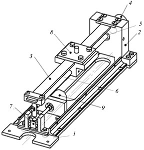
In an effort to overcome these drawbacks, the development team has designed viscous friction damping steady-rest for oscillation suppression during turning or circular grinding operations (Fig. 1).
This vibration damper [6, 9, 10] includes the rack 1 containing two hydraulic cylinders 3 with pistons 2, plungers 7, and rollers 6, which are capable to perform reciprocating motion for adjustment of the workpiece diameter by means of regulation by screws 5 located in the hydraulic cylinder cap 4.
Fig. 2 shows a scheme of the hydraulic cylinder together with the hydraulic circuit.
The hollow plungers 5 with the rollers 6 are connected to the flexible diaphragm 7 by the nut 8 and washers 9. Screws 11 and rings 10 attach the diaphragms to the body of hydraulic cylinders 2. The plungers move along the guide bushings 12 and the pins 13 in the rack 1.
The vibration damper is adjusted to a specified diameter of the workpiece by means of regulating screw 14, which is screwed into the cap 4, fixed by the locknut 15 and pivotally connected to the piston of the hydraulic cylinder 2.
Fig. 1Viscous friction based damper for the suppression of oscillations during turning or circular grinding operations
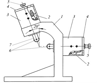
Fig. 2Construction and hydraulic circuit of the connection of hydraulic cylinders
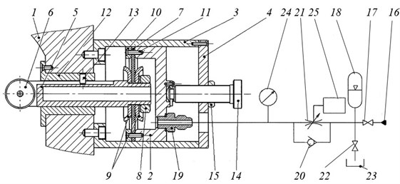
The pressure source 16 creates working pressure in the hydraulic system, which is controlled by the pressure gauge 24 (Fig. 2). The hydraulic fluid enters hydraulic cylinders through the nozzle 19, after which the valve 17 is closed. The throttle 21 adjusts the fluid flow during operation between the cylinder 2 and the hydropneumatic accumulator 18 through the check valve 20. The hydraulic fluid is drained from the hydraulic system to the hydraulic tank 23 through the connected globe valve 22.
After adjusting the technological system machine-fixture-tool-workpiece, the vibration damper is installed. Plungers are fixed to the workpiece by means of screws 14 and are fixed by locknuts 15. Vibrations arising during work on a workpiece are transmitted through the roller 6 to the plunger 5, which moves translationally along the guide bushings 12. The fluid is displaced from the cavity of the hydraulic cylinder through the fitting 19 into the hydraulic system, where the throttle 21 absorbs vibrational energy due to viscous friction. In order to return the plunger 5 to its initial position at decayed pressure in the hydraulic cylinder 2, the energy of the fluid of the hydropneumatic accumulator 18 is used.
When the level of vibration (amplitude and frequency) of the workpiece is changed, the signal measured by a vibration sensor (not shown on the scheme) is supplied to the control system 25, which changes the orifice size of the throttle 21 correspondingly.
The advantages of the damper include extended frequency range of vibration damping, and the ability to adjust the frequency of vibration damping.
The results of researches carried out during milling a loose workpiece on the real equipment (MCV-400 machining center) have confirmed prospects for the use of the proposed device. Reduction of the vibration level increased productivity by two-three times.
3.2. Dynamic vibration dampers
The common dynamic vibration dampers are designed for damping low-frequency vibrations arising in the technology system. They constitute an oscillatory system with an adjustable elastic oscillating element and a vibrational damping element. These vibration dampers have a significant drawback: inability to change the frequency of vibration damping rapidly.
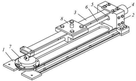
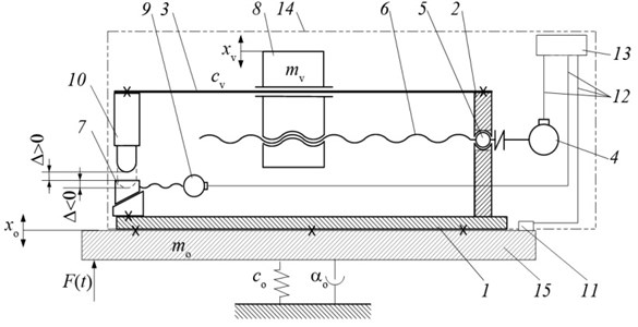
The controlled dynamic vibration damper has been designed in order to extend the damping frequency band [11, 12] (Fig. 3, 4). The absorber consists of the base 2 with a mounted elastic element 3, and a movable weight 8. The damping element 7 is set on the basement 1. The weight drive (stepping motor 4, ball bearing 5, lead screw 6) moves the load to a position, at which the natural frequency of the damper is equal to or approximates the value of the oscillation frequency of the processing equipment; thus, there is an effect of vibration damping.
Fig. 3A schematic diagram of a dynamic vibration damper
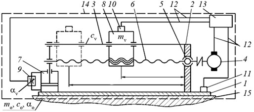
The vibration damper 14 (with base 2, elastic element 3, stepping motor 4, ball bearing 5, lead screw 6) is installed on the table of the processing equipment 15 by the base 1 (Fig. 4), forming a single vibration system with the main parameters: , , , , , – coefficients of viscous resistance, restitution, and mass respectively, referring to the object (table) and the damper.
If vibrations arise on the protected object, the movable weight begins to oscillate in the direction of these vibrations. The sensors 10 and 11 record the level of vibration of the object, and transmit this information via the information channels 12 to the control system 13. The latter gives a control signal to the movable weight drive 8.
The operating frequency range of the damper can also be controlled by adding weights and changing the damping coefficient of the damper 7.
The use of this vibration damper makes tool life 1.2-1.5 times higher, and improves surface undulation from 40 µm to 10…15 µm (MC-032 machining center).
Fig. 4A schematic diagram of a dynamic vibration damper
3.3. Vibration shock dampers
The main disadvantage of the known designs of shock dampers [7, 11, 13] is inability to control the vibration damping frequency.
A scheme of a shock damper designed for damping vibrations, which are perpendicular to the base, is presented in [14].
The design of the damper (with basement 1, base 2, elastic element 3, stepping motor 4, ball bearing 5, lead screw 6, weight 8) (Figs. 5, 6) differs from the previously discussed one by presence of the striker 10 with the stop 7 (instead of the damping element), and the gap adjustment drive 9 allowing precise tuning for the desired vibration frequency. System parameters: , , , – masses, restitution coefficients and viscous resistance coefficients of the protected object and the vibration damper, – the distance between the striker and the stop, , – the displacement functions of the object and the damper, – external disturbance.
Fig. 5A schematic diagram of a shock vibration damper
The principle of operation is similar to the operation of the device shown in Fig. 3. The vibration damper 14 (with base 2, elastic element 3, stepping motor 4, ball bearing 5, lead screw 6) is installed on the protected object 15 by the base 1 (Fig. 6). During the work of the processing equipment the weight 8 on the elastic element 3 starts vibrating, and the control system 13 (with information channels 12 and sensors 11) allows tuning the damper at the desired frequency of vibration damping.
A simple and reliable design of the damper with smaller dimensions comparatively to certain devices along with the possibility of automatic adjustment to the desired vibration frequency offer the prospect of application of the device.
The disadvantage of this damper is insensitivity to high excitation frequencies.
Fig. 6A schematic diagram of a shock vibration damper
3.4. Balancing and self-balancing
One of the reasons for the low-frequency vibration process in the system is unbalance of rotating elements [4, 5, 15, 16] due to the poor mounting of parts, their wear, inhomogeneity of the material etc.
Depending on the type of imbalance, static, torque or dynamic balancing are applied [16].
When the imbalance of rotating elements arises during operation, resulting in uneven wear of the grinding wheel, chipping cutter teeth etc., the devices for damping vibrations in a wide range of excitation frequencies (inertial dynamic dampers) should be used [7, 15, 17]. This may be accomplished, when dampers are presented by the elements capable to adjust their vibration frequency according to the excitation frequency. For instance, such characteristics [7, 15, 17] are typical for the elements capable of carrying out rolling of closed surfaces: a sphere in a spherical cavity, a cylinder in a cylindrical cavity etc. Mounting such elements to the vibrating object results in synchronization of their rolling movement with external excitation. The periodic reaction created by a rotating element resists vibration load. For example, the schemes of the self-balancing system reviewed in the works [15, 17] have proven high working reliability and decreasing vibrations by 12-19 dB while balancing grinding wheels.
3.5. Foundations and anti-vibration mounting of tools
The reasons causing technological system vibration may take effect in the presence of vibrations transmitted from the outside [11, 14, 18-20], such as those of forging machinery, powerful motors, etc. In this case, the anti-vibration mounting of the machinery or mounting equipment on the foundation is performed [19-21].
Let us review the construction of a hydropneumatic shock absorber as an example of a device reducing vibrations [22] (Fig. 7).
The hydraulic shock absorber consists of the intermediate weight 1 moving in the guides 2. The elastic coupling 4 is mounted between the intermediate weight 1 and the base 3. The cavities of elastic couplings 4 are made of high-pressure hoses, filled with fluid, and connected by the pipe 5 to the damper comprising the check valve 9 and the adjustable throttle 6, which are arranged in parallel. The damper is connected to the fluid cavity of the pneumatic pressure tank 7, whilst the gas compartment of the tank is connected to the charging valve 8 and the safety valve 10.
Before starting hydropneumatic shock absorber, the pneumatic pressure tank 7 is set at initial pressure through the charger 8. The same pressure will be in the deformed high-pressure hoses 4 filled with fluid. The safety valve is set to pressure exceeding the pressure .
When a shock load influences the intermediate weight 1, it passes on the high-pressure hoses 4 deformed in the radial direction, and the fluid is pushed out of them. The throttle 6 absorbs vibration energy by means of viscous friction arising when the fluid enters it. Return to the initial position is done by means of the energy in accumulator 7.
Controlling the average pressure in the hoses 4 allows adjusting the rigidity of the system, and change of the orifice size of the throttle allows controlling the damping level.
The use of such vibration isolator (JSC “Sibelektromotor”, Tomsk city) led to significant reduction of vibration level by 60 dB, which has significantly improved the accuracy of the protected precision equipment [23].
Similar designs of the hammer foundations [20, 21] enable reducing the dynamic soil loading by 4-5 times; damping of the vibrations caused by impulse input is performed during one cycle; dimensions of the foundations are significantly smaller comparing to the constructions not capable to control the process of damping.
Fig. 7Hydropneumatic shock absorber
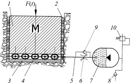
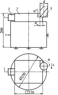
Fig. 8The arrangement of sensors
4. Processing methods of reducing vibration level of the technological system
The processing methods [1, 4, 5, 24] give general recommendations on the reduction of vibration level, and often they are not applicable in certain processing conditions due to many factors causing vibrations, such as tool geometry, cutting modes, mechanical and physical properties of the workpiece etc. Thus, there is a need for carrying out researches.
The authors have implemented into practice a testing technique that helps to reduce the level of the technology system vibration basing on:
– the lathe 1K62 [25];
– the milling machining center MCV-400 [26];
– the five-axis machining center Metrom P1000 [27].
The purpose of this technique is definition of a minimum vibration level through a variation of tool geometry and processing modes.
A hardware and software system is presented in all the cases by a portable measuring device K-5101, and a laptop with installed special mathematic software “Vibroregistrator-F” based on NI LabVIEW (OOO “Vitek”, St. Petersburg, “Vitek-Sibir”, Tomsk).
The method lies in implementing the following steps [27]:
– adjustment of the technological system and installation of the sensors at the points of measuring vibration level, namely vibration acceleration – , m/s2 (Figs. 8-10);
– development of the plan of experiment (Table 1);
– carrying out the experiment (according to the plan) by varying the cutting speed (, m/min) and the feed per tooth (, mm/tooth) with the following parameters:
• cutter material – Н10F;
• cutter diameter 10 mm;
• number of teeth ;
• helix angle of the cutter helical groove – 60°;
• circular pitch (uneven) 93°, 91°, 85°, 91°;
– analysis of the results (Fig. 6) and issuing recommendations.
Basing on the results of the experiment (six passes of cutter at different operating modes while processing workpieces made of steel 40X), the vibrational level (vibration acceleration amplitude) has been defined for each pass. Technological parameters Eq. (1) enabled to calculate the volume of the removed material for each pass of the cutter:
where – depth of milling, mm; – cutting width, mm; – cutter speed, rpm.
Fig. 9Machining center Metrom P1000
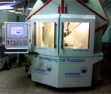
Fig. 10Working area of the machining center Metrom P1000
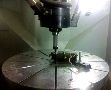
Table 1Plan of the experiment
No. of pass | Cutting modes | No. of pass | Cutting modes | No. of pass | Cutting modes | |||
, m/min | , mm/tooth | , m/min | , mm/tooth | , m/min | , mm/tooth | |||
1 | 100 | 0,02 | 4 | 120 | 0,017 | 5 | 140 | 0,014 |
2 | 0,048 | 5 | 0,04 | 6 | 0,034 | |||
As a result, a unified diagram (Fig. 11) has been designed reflecting dependence of the vibration acceleration amplitude and the amount of removed material on number of the pass. This diagram allows to determine the operating modes preferable for processing operations (with the lowest level of vibration): passes No. 1, 2 and 3.
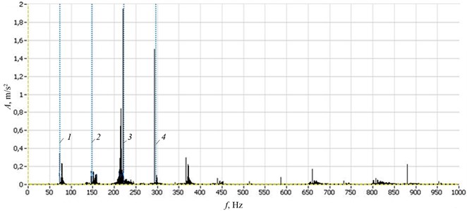
The spectrograms of vibration for two passes are shown for a visual comparison of the vibration levels at various cutting modes (Fig. 12).
Fig. 11Characteristics of technological process at ap= 5,3 mm, ae= 3 mm
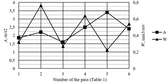
Fig. 12Spectrograms of vibration level: а) pass No. 1; b) pass No. 5, vertical dashed lines correspond to the number of teeth of the cutter (1-4)
a)
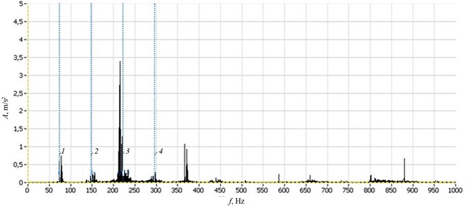
b)
This method has its limitations [28], and works well under conditions of high rigidity of the technological system elements. If the system includes non-rigid elements, as well as production modes involving the presence of low-frequency vibrations of 2-50 Hz, it is better to use constructive methods or combine them with the aforementioned processional methods.
5. Conclusions
1. While searching solutions for minimizing vibration level of technological systems during machining, an integrated approach is required that addresses the reasons causing vibration and their parameters [33-37].
2. An important factor in the design and choice of damping devices is the ability to change the frequency of the vibration damping and its range rapidly. It allows to adjust dampers quickly to the optimal working parameters while changing production modes and working conditions of the technological system.
3. The use of special hardware and software mathematical complex “Vibroregistrator-F” [29] helps identifying the reasons causing vibration, setting optimal working parameters, and maintaining control of vibration damping devices reviewed in this work with minimal time spent in a production environment.
References
-
Bolsunovsky S. A., Vermel V. D., Gubanov G. A., Kacharava I. N., Leontiev A. E. Theoretical and experimental estimation of rational technological parameters for high-performance milling as a part of automated system for aerodynamic aircraft models production tooling. Proceedings of the Samara Scientific Center of the Russian Academy of Sciences, Vol. 14, Issue 4, 2012, p. 374-379, (in Russian).
-
Cochinev N. A., Sabirov F. S., Kozochkin M. P. Software complex of collection, processing and analysis of vibration signals nkRecorder. Сertificate of State Registration of Computer Software No. 2009613214 of the Russian Federation, Vol. 69, Issue 4, 2009, p. 6, (in Russian).
-
Zharkov I. G. Vibrations in Edge Tool Treatment. Mashinostroenie, Moscow, 1986, p. 180, (in Russian).
-
Sinopalnikov V. A., Grigoriev S. N. Reliability and Diagnostics of Technological Systems. Vysshaya Shkola, Moscow, 2005, p. 343, (in Russian).
-
Boldin L.A. Machine Tools (Operational Issues). Mashgiz, Moscow, 1957, p. 260, (in Russian).
-
Gavrilin A. N., Moyzes B. B., Cherkasov A. I. Constructive methods to improve system vibration resistance. Kontrol’. Diagnostika (Testing. Diagnostics), Vol. 2, 2011, p. 82-88, (in Russian).
-
Chelomey V. N. Vibrations in Technics. Reference Book. Vol. 4. Oscillations in Nonlinear Mechanical Systems. Mashinostroenie, Moscow, 1979, p. 351, (in Russian).
-
Trofimov A. N. The Concept of Reaction Coupling in the Dynamics of Mechanical Systems and Processes of Dynamic Damping. Abstract of Dissertation of Candidate of Technical Sciences, Irkutsk, 2012, p. 19, (in Russian).
-
Gavrilin A. N., Angatkina O. O., Rozhkov P. S., Sikora E. A. Russian Patent 2475660, IPC F16 F9/30, F16 F15/027, B23 Q1/76. Viscous Friction Vibration Damper. 2013, (in Russian).
-
Gavrilin A. N., Angatkina O. O., Rozhkov P. S. Innovative developments in the field of productivity and precision improvement on the CNC machines. Kontrol’. Diagnostika (Testing. Diagnostics), Vol. 2, 2011, p. 52-55, (in Russian).
-
Zavgorodskiy V. I., Maslov A. R. Vibration resistance control of the technological system. File: ITO, Vol. 10, 2009, p. 22-25, (in Russian).
-
Gavrilin A. N., Vitko A. V., Krauin’sh P. Y., Rozhkov P. S. Russian Patent 98792, INC F16
-
Gavrilin A. N., Rozhkov P. S., Angatkina O. O., Moyzes B. B. Dynamic vibration damper with automatic adjustment to the frequency of the oscillations. Bulletin of the TPU, Vol. 318, Issue 2, 2011, p. 26-29, (in Russian).
-
Gavrilin A. N., Cherkasov A. I., Moyzes B. B. Adjustable shock absorber with improved parameters. Kontrol’. Diagnostika (Testing. Diagnostics), Vol. 13, 2013, p. 113-114, (in Russian).
-
Nesterenko V. P. Terms of Self-Balancing of a Two-Bearing System with the Help of Balls. Izvestiya Vysshikh Uchebnykh Zavedenii, Mashinostroenie, 1984, p. 63-67, (in Russian).
-
GOST ISO 1940-1-2007. Vibration. Quality Requirements for Rigid Rotors Balancing. Part 1. Determination of Unbalance Tolerance. Standartinform, Moscow, 2007, p. 29, (in Russian).
-
Nesterenko V. P., Sokolov A. P. Patent A.s.1185142, IPC G01 M1 / 36. Self-Balancing Device. 1985, (in Russian).
-
Construction Standards and Regulations: SNiP II-19-79. Foundations of Machines with Dynamic Loads: Normative-Technical Material. Izdatelstvo literatury po stroitelstvu, Moscow, 1980, p. 41, (in Russian).
-
Kucherenko V. A. Design Manual on Vibration Isolation of Machines and Equipment. Stroyizdat, Moscow, 1972. p. 160, (in Russian).
-
Belov S. V. Protective Facilities in Mechanical Engineering. Engineering and Design. Reference Book. Mashinostroenie, Moscow, 1989, p. 368, (in Russian).
-
Zalaeva S. S., Rybka O. A. Industrial Sanitation and Occupational Health. Part 1. Industrial Lighting. Vibration: Tutorial. BSTU Publishing House, Belgorod, 2008, p. 165, (in Russian).
-
Krauin’sh P. Y., Smailov S. A., Moyzes B. B., Voronko I. V., Suprunov A. U., Kuvshinov K. A. Russian patent 2298122 INC7 F16 F15/023. Hydropneumatic Absorber, No. 2005137254/11. 2007, (in Russian).
-
Gavrilin A. N., Ioppa A. V., Govorin R. A. Vibration protection of precision equipment of automated lines. Proceedings of the Regional Scientific-Practical Conference on Engineering Sciences, TPU, Tomsk, 1995, p. 23-25, (in Russian).
-
Iurkevich V. V., Skhirtladze A. G. Reliability and Diagnostics of Technological Systems. Publishing House Academia, Moscow, 2011, p. 304, (in Russian).
-
Gavrilin A. N., Moizes B. B. The method of rapid diagnosis of the machine tool for processing such workpieces as bodies of revolution. Kontrol’. Diagnostika (Testing. Diagnostics), Vol. 9, 2013, p. 81-84, (in Russian).
-
Gavrilin A. N. The method of reducing vibration during machining. Kontrol’. Diagnostika (Testing. Diagnostics), Vol. 11, 2013, p. 23-26, (in Russian).
-
Gavrilin A. N., Moizes B. B., Cherkasov A. I. Research methods of milling technology elements. Applied Mechanics and Materials, Vol. 756, 2015, p. 35-41.
-
Gavrilin A. N., Rozhkov P. S., Korovin G. I., Sikora E. A. Analysis of tool functioning state with enhanced vibration resistance in high-speed milling. XVIII International Scientific Practical Conference of Students, Postgraduates and Young Scientists on Modern Equipment and Technologies, Tomsk, Vol. 1, 2012, p. 311-312, (in Russian).
-
Gavrilin A. N., Vinogradov A. A., Serebryakov K. V. Certificate of State Registration of the computer program No. 2014618793 “Vibroregistrator-F” in collaboration with the partner organization of LLC “Vi Tech Sibir”, (in Russian).
-
F6/004. Dynamic Self-Adjusting Vibration Absorber. 2010, (in Russian).
-
Barmin B. P. Vibrations and Cutting Modes. Mashinostroenie, Moscow, 1972, p. 72, (in Russian).
-
Gavrilin A. N., Angatkina O. O., Rozhkov P. S., Sikora E. A. Mathematical model of viscous friction vibration absorber for processing such elements as bodies of revolution. Bulletin of the TPU, Vol. 321, Issue 2, 2012, p. 117-120, (in Russian).
-
Gavrilin A. N., Moyzes B. B., Cherkasov A. I. Research methods of milling technology elements. Applied Mechanics and Materials, Vol. 756, 2015, p. 35-40.
-
Colin G. Generic criteria for vibration-sensitive equipment. Proceedings of International Society for Optical Engineering (SPIE), Vol. 1619, 1991, p. 71-85.
-
Colin G. Generic vibration criteria for vibration-sensitive equipment. Proceedings of International Society for Optical Engineering (SPIE), Conference on Current Developments in Vibration Control for Optomechanical Systems, Denver, 1999.
-
Amick H., Gordon C. On generic vibration criteria for advanced technology facilities with a tutorial on vibration data representation. Reprinted from Journal of the Institute of Environmental Sciences, Vol. 40, Issue 5, 1997, p. 35-44.
-
Amick H., Gordon C. Vibration data representation for advanced technology facilities. Proceedings of 12th ASCE Engineering Mechanics Conference La Jolla, California, 1998, p. 306-309.
About this article
