Abstract
Based on free interface component modal synthesis method, the free vibration behavior of wind turbine structures is investigated. The wind turbine structure is divided into three parts including tower, wheel hub-cabin and rotor. The tower is modeled as an isotropic metal cantilever beam, the blade as thin-walled composite beam and the wheel hub-cabin as a rigid body due to its large extensional stiffness, bending stiffness and torsion stiffness compared with tower and blades. The displacements of the blades are described by thin-walled composite beam theory. Galerkin’s method is used to discretize blades and tower. Employing Lagrange method, the motion equations of blades are derived and then stiffness and mass matrices are obtained. The natural frequencies and mode shapes of the wind turbine structure are predicted by numerical simulations. Numerical results using the present model are validated by ANSYS software results.
1. Introduction
Large horizontal axis wind turbines are sophisticated dynamic systems in which structural dynamic and aeroelastic stability problems can be frequently suffered from. These problems appear because of the highly variable turbulent atmospheric wind environment that flexible composite blade system encounters, as it rotates. In order to further improve the dynamical performance of wind power generators, a comprehensive model is therefore essential.
Currently, the most widely used structural modeling method of wind turbine is multi-body dynamical method. Several multi-body dynamical formulations have been presented for the analysis of horizontal axis wind turbines [1-7]. Typically, flexible components, such as tower and rotor blades, are discretized by an FE method. In general, in order to provide an accurate system model, many degrees of freedom for each component need to be involved. Thus, the total degrees of freedom will increase significantly, which will in turn increase the computational effort, especially for such time-dependent systems as large wind power generator systems. Substructure or component modal synthesis is useful to model large and complex mechanical systems where the exact solution is not available or numerical techniques are inefficient. However, to the best of the author’s knowledge, no literature on structural dynamic modelling of a wind turbine by component mode synthesis is cited, though a recent study has been found in the dynamical analysis of the wind turbines FE based simulations for rotor blades [6].
The main problem of in the design of wind turbine is load carrying capacity and the fatigue resistance due to dynamic instabilities. As first part of the dynamical design of wind turbine, the structural modelling (no aerodynamic loads is included) and analysis of the basic dynamic properties, such as natural frequencies and mode shapes are of vital importance for further investigation of stability problems and structural integrity of the entire wind turbine. The goal of this paper is to present a simpler and less computationally expensive model in order to investigate dynamic characteristics of wind turbine. Free interface component modal synthesis method is used to calculate the natural frequency of wind turbine. The tower is modeled as an isotropic metal cantilever beam, the rotor blades as composite thin-walled closed section beam. A composite thin-walled beam theory, which is an asymptotically correct theory referred to as variational asymptotically method (VAM) [8] is applied to obtain the displacement field in the rotor. Galerkin’s approach is used for the discretization in space for blades and tower. By using the continuity conditions of the deformation, mass and stiffness matrices of these flexible components are assembled to get mass and stiffness matrices of whole wind turbine system. Natural frequencies of wind turbine are evaluated from the free vibration solution. The finite element analysis software, ANSYS is also used to calculate the natural frequencies of wind turbine in order to examine validity of the present model.
2. Wind turbine modeling
The deformations of cabin and wheel hub are very smaller than the blade and tower. So it’s reasonable to model the cabin and wheel hub as rigid body, whereas blade and tower as flexible body. The structural model and coordinate systems are shown in Fig. 1. Inertia coordinate system , which is fixed, and coordinate origin is located at the right center of wheel hub before deformation. Tower coordinate system , which describes the tower motion, and coordinate origin is located at the root of tower. And it doesn’t move during vibration. Cabin coordinate system , which describes cabin motion. The coordinate origin is located at the center of cabin, and just at the top of tower. It moves along with the tower wheel hub coordinate system , which describes the motion of wheel hub. The coordinate origin is located at the wheel hub center. And it moves with the cabin and tower. Blade coordinate system , which describes the blade motion. Its coordinate origin is located at the wheel hub and moved with the cabin and tower.
Based on the structural characteristics of wind turbine, it is divided into three parts: rotor, wheel hub and cabin, tower. This is convenient to apply modal synthesis method.
Fig. 1Wind turbine structural model and coordinate systems
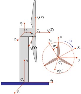
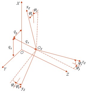
Fig. 2Inertia coordinate system and wheel hub coordinate system after deformation
3. Free vibration characteristics of subsystems
3.1. Free vibration characteristics of rotor
The wheel hub coordinate system and blade coordinate system are moveable because of the displacements of tower and cabin as shown in Fig. 2. , , are displacements and , , twist angles of wheel hub in inertia coordinate system.
Besides all above rigid displacements, the blades have elastic deformations. Let , and represent the average displacement along , , directions while represents the twist angle about -axis, and the subscript ( 1, 2, 3) identifies the ith blade. So the rotor has 6 rigid displacements and 12 elastic displacements.
3.1.1. Transformation matrix from inertia coordinate system to blade coordinate system
In order to derive the kinetic energy of rotor, the rotate transformation matrix from inertia coordinates to blade coordinates must be used.
The inertia coordinate rotates about -axis, about -axis and about -axis to the coordinate system of first blade. It rotates same angle about -, -axis to the coordinate system of second and the third blades. While rotate and about -axis to the coordinate system of second and third blades, respectively.
Letting , , , the transformation matrix from inertia to the blades’s coordinate system is:
3.1.2. Kinetic energy density of rotor
The displacement vector of any point on the first blade can be expressed in terms of the inertia coordinate system:
where , , are the displacements of any point on the cross-section of the first blade in , , direction. Based on Ref. [8], the displacement fields are assumed:
Based on the displacement vector and coordinate transformation, the velocity of the first blade is expressed as:
The kinetic energy of per unit length is:
By combining the transformation matrix with Eq. (4), Eq. (6) and Eq. (7), the kinetic energy of the first blade can be obtained. And similarly, the kinetic energy of the second blade and the third blade can also be obtained.
Thus the kinetic density of rotor takes the form:
3.1.3. Strain energy density of rotor
Based on Ref. [9], the per unit length strain energy of the first blade takes the form:
where, .
In Eq. (9), the first term is the strain energy due to deformation of the composite blade, the second and third terms are the strain energy due to rotating motion of the blade, where, is a 4×4 symmetric stiffness matrix, is the mass of per unit length, is the thickness of the blade at any point, and denote first and second differentiation with respect to , respectively, and denote first and second differentiation with respect to , respectively.
The strain energy density and of second and third blades can also be obtained just by substituting the displacement variables into Eq. (5) with their corresponding variables.
So the strain energy density of the rotor can be written as:
3.1.4. Gravitational potential energy density of rotor
The gravity acts on the blades along the inertia negative axis. The gravitational potential energy density of the first blade takes the following form:
where, can be found in Eq. (4).
Next, one can obtain the gravitational potential energy density of the second blade and the third blade .
Thus gravitational potential energy density of the rotor is:
The Lagrange density of rotor [10] can be written as:
3.1.5. Mass matrix and stiffness matrix of rotor
The mode shape of rigid motion variable , , and , , is assumed to be . And elastic deformation variable is assumed to take the standard non-rotating, non-coupling, uniform cantilever beam mode shape functions as:
where, is number of mode shapes.
Substitution the mode shape function Eq. (14) into Eq. (13), then integrating along the blade length, the Lagrange function can be obtained. Based on the Lagrange equation, the elements of mass matrix and stiffness matrix of the rotor are just the coefficients of corresponding variables, so the and can be derived directly according to the Lagrange function.
3.2. Free vibration characteristics of wheel hub-cabin and tower
The tower, wheel hub-cabin are considered as simple isotropic beams. So their vibrations dispalcements can be discribed based on the classical extension, bending and torsion beam theory. And the tower is a cantilever beam, and wheel hub-cabin can be simplified as a free-free beam.
The tower has 4 degrees of freedom by , , , , where, denotes displacements along , denotes deflection along , denotes deflection along and denotes torsion about . And its mode shape is same as in Eq. (14). While the wheel hub and cabin have 4 elastic displacements and 6 rigid displacements caused by the deformation of tower.
The motions of cabin and wheel in every direction can be expressed as:
Displacement along direction:
Displacement along direction:
Displacement along direction:
Rotation about :
where, the mode shape of rigid motion is also supposed to be , and the mode shapes of free-free beam can be represented in the form:
where, is number of mode shape.
Based on Galerkin’s method, one can obtain the mass matrix and stiffness matrix of tower, wheel hub and cabin, which are denoted by , , , .
4. Free vibration characteristic of wind turbine
By assembling the subsystem’s mass and stiffness matrices, the whole wind turbine mass and stiffness matrices take the form:
where, and are 32×32 symmetric matrices. The 32 variables are not independent. The deformations are continuous at the interface of tower and cabin, and at the interface of wheel hub and rotor. So the following relations have to be fulfilled:
By using Eqs. (21), the transformation matrix can be formed from which one can reduce and from 32 variables to 20 variables. Thus, the mass and stiffness matrices of wind turbine described as Eqs. (20) become:
The expressions for , , , , and are not shown for the sake of simplicity. From and , the generalized eigenvalue problem can be yielded. So the free vibration of wind turbine system can be studied by the eigenvalue equations.
5. Numerical examples
The blades is a thin-walled box beam made of T300/5208 graphite/epoxy composite material, while tower and wheel hub-cabin are isotropic hollow cylinder beams. The geometric and material properties of the blades, the tower and the wheel hub-cabin are given in Table 1 and Table 2, respectively. These property parameters are chosen from 2.5 MW wind turbine data. Applying Eqs. (22) to obtain the mass and stiffness matrices of wind turbine, the free vibration frequencies of the wind turbine can be calculated.
Table 1The geometric and material properties of the blades
Length 44.2 m | Ply thickness 0.05 cm |
Width 2 m | Depth 0.4 m |
Number of piles 100 | kg/m3 |
142 GPa | 9.8 GPa |
6 GPa | 4.83 GPa |
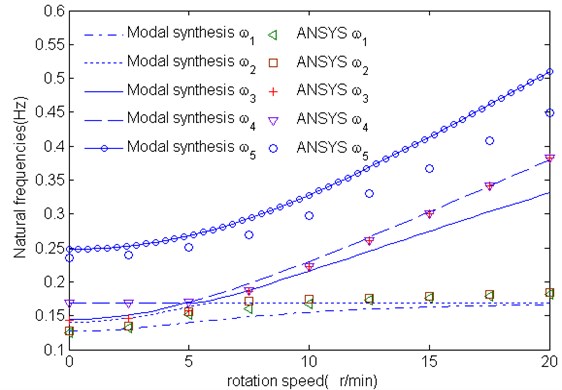
The first five natural frequencies of the wind turbine obtained by the present model in the still state are shown in Table 4. They are compared with the corresponding results of ANSYS software. For ANSYS, SHELL 99 element is chosen to discrete the blade, while BEAM44 is used to discrete the tower, wheel hub and cabin. The connects between the wheel hub and blades are assumed as rigid constraints. Gravity and rotating speed are loaded on the blades. A perfect agreement of numerical results using the present model with ANSYS results can be seen from Table 4.
Table 2The geometric and material properties of the tower
Height 80 m | Outer diameter 2.515 m |
Inner diameter 2.485 m | 200 GPa |
0.3 | kg/m3 |
Table 3The geometric and material properties of the cabin-wheel hub
Length 3 m | Outer diameter 2.3 m |
Inner diameter 2 m | 20000 GPa |
0.3 | kg/m3 |
Table 4First five natural frequencies (Hz) of the wind turbine with Ω= 0 r/min
Method | 1st | 2nd | 3rd | 4th | 5th |
Modal Synthesis | 0.1271 | 0.1396 | 0.1435 | 0.1689 | 0.2474 |
ANSYS | 0.1242 | 0.1272 | 0.1426 | 0.1686 | 0.2355 |
The variation of first five natural frequencies vs. rotating speed of rotor blades is shown in Fig. 3 from the present model with the ones from ANSYS software. As it appears from these figures, natural frequencies increase as the rotating speed is increased, because of the existence of a larger centrifugal forces at a higher rev/min, which is called as the dynamic stiffening. However, it can be noted that the effect of the rotating speed appears to be not significant for the lower-mode ones. It can also be observed that the results from the present model in general, agree well, as compared with ANSYS, at lower rotating speed. Fig. 3 shows close agreement between the present model and ANSYS results for the first mode, second mode and fouth mode. And the third mode and fifth mode depart slightly in magnitude at higher rotating speed but still have the same trend.
Fig. 3Variation of first five natural frequencies with rotating speed
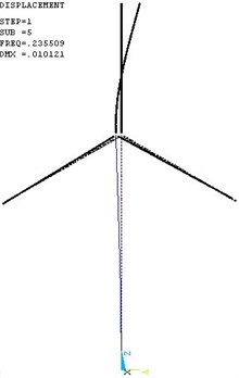
The first five mode shapes are shown in Fig. 4 to Fig. 8. The most important dynamic properties of the complete wind turbine structural systems can be seen from these figures, they are: the flap and lag vibrations of rotor blades (see Figs. 4-5), the vibration interactions of the rotor blades and tower (see Figs. 6-8).
Fig. 4The first mode shape
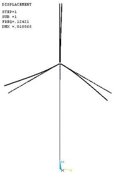
Fig. 5The second mode shape
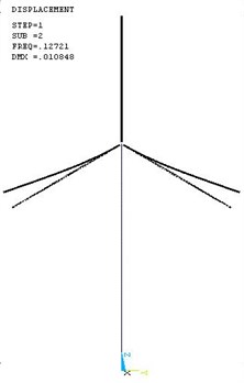
Fig. 6The third mode shape
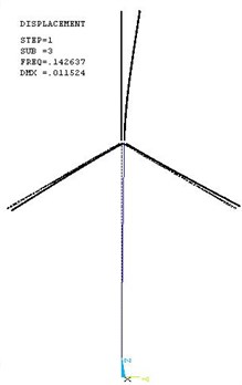
Fig. 7The fourth mode shape
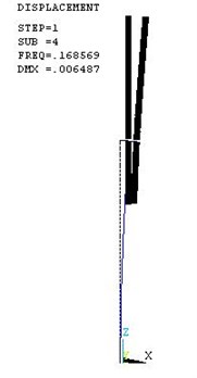
Fig. 8The fifth mode shape
6. Conclusions
This paper deals with the structural dynamical modeling of wind turbine. An analytical model capable of predicting of the natural frequencies of wind turbine has been proposed based on free interface component modal synthesis method. The present model employs thin-walled composite beam theory that can be used effectively for the analysis of tubular thin-walled composite blades. Flexible subsystems as blades and tower are discretized using Galerkin’s method that is computationally efficient compared to the traditional finite element method when applied to compute the dynamic behavior of wind turbine. Results obtained by the present model are agreement with the ANSYS results. Our study exhibits the capability of component modal synthesis method to model the wind turbine. This work is a part of a project on structural dynamics and aeroelastics of wind turbine, and the model will be extended to include aerodynamic loads arising from the imposed wind field and be used for analysis of stability problems of wind turbine.
References
-
Stol K. Dynamics modeling and periodic control of horizontal-axis wind turbines. Ph. D. Thesis, University of Colorado at Boulder, Boulder CO, USA, 2001.
-
Zhao X. Y., Peter M., Wu J. Y. A new multibodymodeling methodology for wind turbine structures using a cardanic joint beam element. Renewable Energy, Vol. 32, Issue 3, 2007, p. 532-546.
-
Lee D. H., Dewey H., Hodges P., Mayuresh J. P. Multi-flexible-body dynamic analysisof horizontal axis wind turbines. Wind Energy, Vol. 5, Issue 4, 2002, p. 281-300.
-
MaiXer P. A differential-geometric approach to the multibody system dynamics. Journal of Applied Mathematics and Mechanics, Vol. 71, Issue 4, 1991, p. 116-119, (in German).
-
Schiehlen W. Advanced Multibody System Dynamics-Simulation and Software Tools. London, KluwerAcademic Publishers, 1993.
-
Holm-Jorgensen K.,Nielsen S. R. K. A component mode synthesis algorithm for multibody dynamics ofwind turbines. Journal of Sound and Vibration, Vol. 326, Issue 3-5, 2009, p. 53-767.
-
Wang J. H., Qin D.T., Lim T. C. Dynamic analysis of horizontal axis wind turbine by thin-walled beam theory. Journal of Sound and Vibration, Vol. 329, Issue 17, 2010, p. 3565-3586.
-
Berdichevsky V. L., Armanios E., Badir A. M. Theory of anisotropic thin-walled closed-cross section beams. Composites Engineering, Vol. 2, Issue 5-7, 1992, p. 411-432.
-
Choi S. C., Park. J. S., Kim J. H. Active damping of rotating composite thin-walled beam susing MFC actuators and PVDF sensors. Composite Structures, Vol. 76, 2006, p. 362-374.
-
Zhong Y., Zhou L. Z. Basic theory of analytical mechanics. Beijing, Metallurgical Industry Press, 2006, (in Chinese).
About this article
The research is funded by the National Natural Science Foundation of China (Grant Nos. 10972124, 11272190) and Shandong Provincial Natural Science Foundation of China (Grant No. ZR2011EEM031).
