Abstract
The main objective of this paper is to investigate the influence of Pile-Soil-Structure Interaction (PSSI) on pounding responses of adjacent buildings earthquakes. Firstly, based on Penzien PSSI model and the contact element of Hertz-damp, the analytical model for pounding of adjacent buildings considering the influence of PSSI is developed. The motion equations of pounding are derived. Secondly, the numerical investigation for the pounding of two adjacent frame structures with pile-foundation is conducted and the influence of PSSI on pounding of adjacent buildings is studied. Finally, paramterical studies about the influences of soil and structural property on the response of pounding are examined. The results show that the PSSI has an obvious influence on pounding of adjacent structures with pile foundation. The property of soil and structures, such as shear-wave velocity of soil and stiffness of pile, play significant roles on the pounding of adjacent buildings.
1. Introduction
Structural pounding of adjacent buildings with insufficient separation have been observed frequently during earthquakes. Pounding may result in substantial damages or even collapse of structures. The collapse of the roof parapet due to pounding between parts of school buildings was observed in the Athens earthquake of 7 September 1999 [1]. Rosenblueth and Meli [2] reported that about 40 % of the damaged structures experienced pounding in the Mexico City earthquake of 19 September 1985, and 15 % of them leading to structural collapse. During the San Fernando earthquake (09 Feb. 1971), the structural pounding between the main building of the Olive View Hospital and one of its independently standing stairway towers led to the permanent tilting of stairway tower [3]. During the Loma Prieta earthquake (17 Oct. 1989), over 200 pounding occurrences and more than 500 buildings were observed damaged within the area of 90 km from epicenter [4].
Recently, the pounding of adjacent buildings during earthquakes has been investigated intensively. Various models for structures and collisions were proposed [5, 6]. A fundamental study on pounding of adjacent buildings was conducted by Anagnostopoulos [7]. In his analysis, structures were modeled by Single-Degree-of-Freedom (SDOF) systems and impact forces were model by the linear viscoelastic models. Maison and Kasai [8] employed the multi-degree-of-freedom models with lumped story’s mass to analyze earthquake-induced pounding between a light high-rise building and a massive low structure. In their model, a single linear spring at the roof level of the lower structure was used to model the impact force during collision. Anagnostopoulos and Spiliopoulos [9] also used lumped mass models of 5-story and 10-story buildings to conduct the parametric study on pounding-involved structural behavior. The study on multi-degree-of-freedom models of colliding structures of unequal story heights was also carried out in order to examine the effect of inter-story pounding [10]. In this case, impact elements, which were modeled as rigid body, were used to simulate contacts at different locations.
Most of studies assumed that the structures were built on fixed bases [8-10] despite the fact that many structures foundation were actually soft materials. Since the seismic response of a structure is influenced by the medium on which it is founded, the Soil-Structure Interaction (SSI) has two basic effects on structural response. Firstly, the number of degrees of freedom in model considering SSI is increased, and the dynamic characteristics are modified. Secondly, a significant part of the vibration energy of the SSI system may be dissipated either by reflected waves which is emanated back from the foundation–structure interface into the soil, or by hysteretic material damping in the soil. Therefore the systems considering SSI have longer natural periods of vibration than their counterparts with fixed-base. Moreover, the simplified system without SSI consideration ignores the reality that a structure is not subjected to the free-field ground motion. The property of ground excitation depends on the dynamic character of both the foundation soil and the superstructure.
The pile foundation is one of the most popular building foundation forms, and the effect of Pile-Soil-Structural Interaction (PSSI) has been observed by many scholars. There are many models proposed to simulate the influence of PSSI. Among these models, Penzien model is one of the most widely used methods to simulate the PSSI of pile foundation. This model is composed of pile and free field systems, and the horizontal spring-damper system is set between them. In this system, the ground motions of free field are used as the input excitation. The reliability of this model has been proved by the shake table tests of Wei et al. [11] and Lou et al. [12]. However, almost all of studies focused on the influence of buildings, and few of them discussed the influence of PSSI on pounding of adjacent buildings.
The purpose of this paper is to investigate the influences of PSSI on pounding of adjacent buildings with pile foundations. The analytical models with PSSI consideration are established and the equations of motions are developed. The parametrical study about the influence of soil and structural on pounding is also conducted.
2. Models
2.1. Model of contact element for pounding
There are two main methods, stereo-mechanism and contact element approaches, which are usually used to investigate the pounding of buildings. The stereo-mechanical approach, which is based on the equalization of pounding energy and ignores the process of pounding, is usually applied to single degree-of-freedom mass-spring systems. The contact element approach is a force-based approach, in which a contact element is activated in the pounding point once impact occurs. Generally, there are four contact element models: linear spring, Kelvin model, Hertz model and Hertz-damp model. Among them, Hertz-damp model is the most precise one in simulating the pounding-involved structural response [5, 6]. In this paper, the Hertz-damp contact element is used to simulate the pounding of adjacent structures.
Fig. 1Hertz-damp contact element
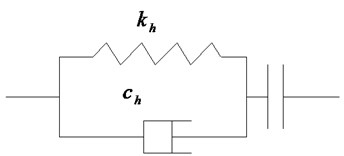
Fig. 1 shows the model of Hertz-damp contact element. A nonlinear spring is employed to simulate the pounding of adjacent building, and a nonlinear viscous damper is used to simulate the energy dissipation during the pounding. The impact force can be computed by:
where and are the displacements of two pounding adjacent buildings at the potential pounding position, respectively; is the separation distance of buildings, and is the nonlinear stiffness of impact element. Since the main purpose of this paper is to investigate the influence of PSSI on pounding, is assumed to a constant in this paper. can be obtained by:
where is the damping ratio. Assuming that the dissipated energy of structures during pounding are due to the damper, can be obtained by [13]:
Fig. 2Computational model of adjacent buildings
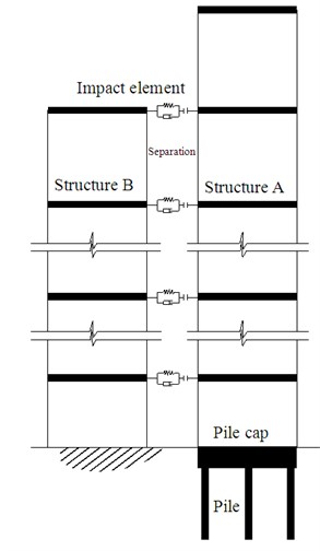
a) Adjacent buildings
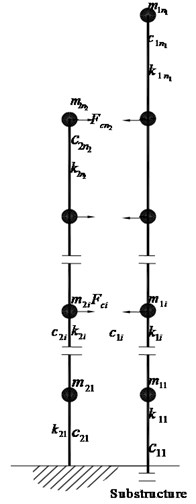
b) Model of superstructure
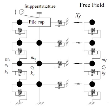
c) Model of pile
2.2. Model of adjacent structures with pile foundation
A system of two adjacent buildings and its corresponding model are shown in Fig. 2. Structure A is an -story building with a pile foundation, and Structure B is an -story building with a fixed foundation. Both the superstructure and the pile are simplified as multiple-degree-of freedom system. All of the piles are incorporated into an equivalent pile. An equivalent bending spring is applied on the location of pile platform to model the rotational stiffness. The soil surrounded the pile is simplified to equivalent spring-mass systems, and connects rigidly with the pile.
Base on the hypothesis and models, the motion equations of superstructure, substructure of Structure A can be expressed as:
where , and are mass, damping and stiffness matrices of superstructure respectively; , and are -dimensional acceleration, velocity and displacement vectors of superstructure respectively; , and are mass, damping and stiffness matrices of simplified pile model respectively; , and are -dimensional acceleration, velocity and displacement vectors of substructure respectively; , and are mass, damping and stiffness matrices of surround soil respectively; , and are respectively k-dimensional acceleration, velocity and displacement vectors of unit soil column in free field; is the acceleration of ground; and are the rotational damping and stiffness of pile cap; is the rotational angle of pile cap; and are the identity vectors for super-structure and sub-structure respectively; H is an – dimensional height vector of building floors, is the matrix of pounding force, and is the location matrix of potential pounding location. Eqs. (4)-(6) can be written to an equivalent equation:
where , and are mass, damping and stiffness matrices of system A respectively;, and are respectively acceleration, velocity and displacement vectors of Building A; is the degrees of freedom of the system, and ; is the acceleration vector of free field input. The matrices can be expressed as:
Similarly, the motion equation of Structure B is expressed as:
where , and are mass, damping and stiffness matrix of Structure B respectively; , and are acceleration, velocity and displacement vectors of Structure B respectively; is the identity vectors for Structure B. Eqs. (7) and (8) can be rewritten as:
where
And , and are the acceleration, velocity and displacement vectors of system, respectively.
2.3. Responses of unit soil column
A unit area of soil column is considered as the model of free field. Assuming that the soil of free field is divided into layers from top to bottom, the equivalent lumped mass is:
where and are the height and density of -th layer soil. The horizontal stiffness of -th layer is:
where is the shear module of th layer. The damping matrix of unit soil column is expressed in Rayleigh damping as:
where and can be calculated by:
where 1, …, ; is the damping ratio of -th layer. Thus, the dynamic motion of unit soil column is:
This motion equation can be solved by Newmark method. The result is then used excitation acceleration vector in Eq. (7).
2.4. Mass, stiffness and damping of equivalent soil column
During the vibration of pile, the soil which surrounds the pile also vibrates. Assuming the area of vibrating soil is equal to the area of pile cap, the mass of additional vibrating soil can be approximated as:
where is the density of soil; is the area of plat cap; is the height of -th layer of soil.
Based on Mindlin method, the horizontal stiffness of soil can be calculated approximately by [14]:
where, is the Young's modulus of soil in the depth of ; is the length of -th pile segment.
The horizontal damping of soil can be obtained by:
where is the radius of pile; is the height of -th layer of soil; is the velocity of wave; is the velocity of shear wave. They can be expressed as:
where is the Poisson’s ratio; is the shear modulus.
Table 1Properties of the sections
Members | Area (m2) | Inertia moment (m4) |
6~10 story beam | 175.2×10⁻⁴ | 7.88×10⁻⁴ |
1~5 story beam | 288.4×10⁻⁴ | 12.95×10⁻⁴ |
9~10 story column | 86.1×10⁻⁴ | 3.94×10⁻⁴ |
7~8 story column | 142.8×10⁻⁴ | 6.84×10⁻⁴ |
5~6 story column | 200.2×10⁻⁴ | 9.75×10⁻⁴ |
3~4 story column | 272.0×10⁻⁴ | 12.66×10⁻⁴ |
1~2 story column | 340.4×10⁻⁴ | 15.57×10⁻⁴ |
Table 2Properties of soil layers
Layer number | Thickness (m) | Poisson ratio | Mass density (g/cm3) | Shear wave velocity (m/s) |
1 | 1.0 | 0.45 | 1.99 | 190 |
2 | 3.5 | 0.40 | 1.82 | 245 |
3 | 2.0 | 0.45 | 2.04 | 206 |
4 | 3.8 | 0.40 | 1.82 | 280 |
5 | 6.5 | 0.45 | 2.06 | 351 |
6 | 10.0 | 0.40 | 1.90 | 350 |
7 | 20.0 | 0.45 | 2.00 | 400 |
3. Numerical investigation
A system of two adjacent frame structures, Structure A and Structures B, is considered and shown in Fig. 2. Structure A is a 10-story frame structure with pile foundation, and the parameters of section and soil layers are shown in Table 1 and Table 2. The mass of each story is 2×10⁵ kg. The span and the height of each story are 6 m and 4 m respectively. The dimension of foundation platform is 8 m×8 m×1 m. There are 4 reinforced concrete piles of 20 m long with section of 0.3 m×0.3 m located under each column. Structure B is a 4-story frame structure with fixed foundation. The story mass and stiffness coefficients in Structure B are 1.8×10⁵ kg and 4×10⁶ kN/m respectively. The damping ratios of structures and pounding are 1.8 % and 0.1 % respectively. The separation between two parts is 0.05 m, and the stiffness of pounding spring is 2×10⁵ kN/m. The scaled ground motion of El Centro earthquake (north-south component) with maximum acceleration of 0.2 g is used as the input excitation.
3.1. Time history of pounding
The structural responses histories of 4 cases: (1) no pounding with PSSI; (2) no pounding without PSSI; (3) pounding with PSSI; (4) pounding without PSSI, are obtained and shown in Figs. 3-10.
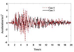
Fig. 3 shows the roof displacement of Structure A when its foundation is assumed to be fixed. It can be seen that the roof displacement in pounding case (case 4) is about 15 % smaller than that in no pounding case (case 2) when the PSSI of Structure A is not considered. The main reason is that the free vibration of Structure A is blocked by Structure B in pounding location, which results in the decrease of roof displacement. Fig. 4 and Fig. 5 are roof displacement of Structure A. They show that the influence of PSSI on roof displacement of Structure A in no pounding case (Fig. 4) is relatively small (less than 10 %), but the influence of PSSI on displacement of Structure A in pounding case (Fig. 5) is very large. The displacement in case 3 is nearly 50 % larger than that in case 4. The main reasons are: (1) when the PSSI is considered, the difference of natural frequency between Structure A and Structure B increases. Thus, the asynchronous vibration of adjacent buildings becomes violent and the pounding of adjacent buildings will happen easily; (2) when the PSSI is considered, the lateral stiffness of Structure A decreases. Hence the separation distance of adjacent buildings becomes relatively insufficient, and the pounding of adjacent buildings will be violent.
Fig. 3Response history of roof displacement of Structure A without PSSI
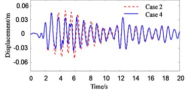
Fig. 4Response history of roof displacement of Structure A (in no pounding case)
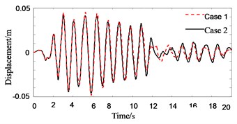
Fig. 5Response history of roof displacement of Structure A (in pounding case)
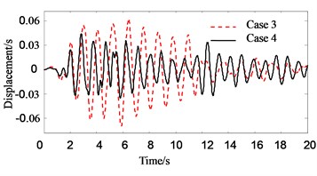
Fig. 6Response history of top floor displacement of Structure B
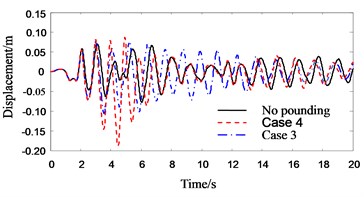
Fig. 7Response history of roof acceleration of Structure A without PSSI
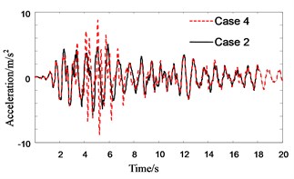
Fig. 8Response history of roof acceleration of Structure A (in no pounding case)
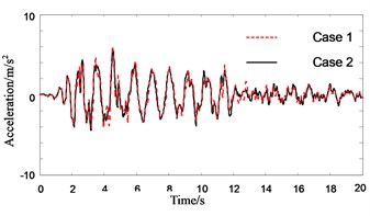
Fig. 9Response history of roof floor acceleration of Structure A (in pounding case)
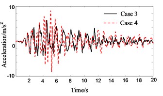
Fig. 10Response history of roof acceleration of Structure B
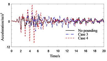
Fig. 6 shows the roof displacement of Structure B. Unlike Structure A, the roof displacement of Structure B with PSSI consideration is about 60 % smaller than that without PSSI consideration. The reason is that the Structure A becomes flexible when the PSSI is considered. Thus, the pounding force weakens and the pounding pulse wanes.
Figs. 7-9 show the response histories of roof acceleration of Structure A. From Fig. 7 it can be seen that the pounding pulse of acceleration is very obvious when the PSSI is not considered. The acceleration in pounding case is about 55 % larger than that in no pounding case. The influence of PSSI on the acceleration response in no pounding case is relatively small (Fig. 8). But it is very obvious on the acceleration response in pounding case. The roof acceleration in case 3 is 35 % smaller than that in case 4 (Fig. 9). This is probably due to the reason that the Structure A becomes more flexible and the pounding force weakens when the PSSI is considered. Similarly, the roof acceleration of Structure B in case 3 is much smaller than that in case 4 (Fig. 10).
Figs. 11-16 show the response histories of 4th floor acceleration and displacement of Structure A. They show the similar trends to those of roof floor, the only difference between them is that their peak values of 4th floor are some smaller than those of roof floor.
Fig. 11Response history for 4th floor displacement of Structure A without PSSI consideration
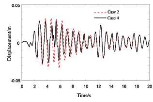
Fig. 12Response history for 4th floor displacement of Structure A in no pounding cases
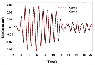
Fig. 13Response history for 4th floor pounding displacement of Structure A in pounding cases
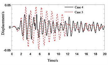
Fig. 14Response history for 4th floor acceleration of Structure A without PSSI consideration
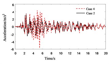
Fig. 15Response history for 4th floor acceleration of Structure A in no pounding cases
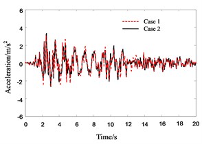
Fig. 16Response history for 4th floor acceleration of Structure A in pounding cases
3.2. Influence of separation distance
The separation distance between adjacent buildings plays an important role on their pounding during earthquake. In order to investigate the influence of separation distance on the pounding behaviors of adjacent buildings, all conditions except the separation are assumed unchanged. The response histories of the system with varied separation distance are computed.
Fig. 17 shows the relationship between the peak displacement of roof floor and separation distance. It can be seen that if the foundation of Structure A is assumed to be fixed, the pounding displacement of Structure B decreases rapidly with increasing separation distance in the beginning, and then it becomes flat gradually. When the separation distance approaches 0.08 m, the displacement tends to be a constant value. The roof displacement of Structure A increases initially, and then decreases gradually with increasing separation distance. When the separation distance approaches 0.06 m, the displacement approaches a constant value. The maximum value of displacement is observed when the separation distance is about 0.04 m. If the PSSI of Structure A is considered, the roof displacements of both Structure A and B decrease with increasing separation distance, but maximum values of roof displacement are also appear at the separation distance of 0.01 m and 0.03 m respectively. It should be noted that the maximum roof displacement of Structure B happen in about 0.13 m when the foundation of Structure A is fixed, which is much larger than that of both Structure A and Structure B in any other cases. The main reason for this observed behavior is that the roof displacement is affected by the stiffness, velocity and acceleration of structures. Between the two pounding structural bodies, the one with softer stiffness gets the larger response after pounding. When the foundation of Structure A is fixed, the stiffness of Structure B is much softer than that of A. Thus Structure B has the larger pounding responses. Generally, the larger the vibrating velocity and acceleration are, the bigger the pounding response will be. When separation distance is small, the acceleration becomes very large and the velocity becomes very small. But when separation distance is large, the velocity becomes very large and the acceleration becomes very small. When the separation distance is large enough, the pounding of adjacent buildings will not happen, and the displacement of buildings tends to a constant value. Hence, there exists a separation distance where the roof displacement has the maximum value.
Fig. 17The relationship between roof displacement and separation distance
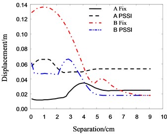
Fig. 18The relationship between acceleration of top floor and separation distance
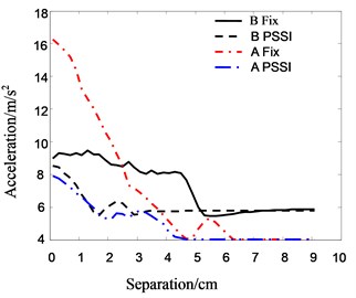
Fig. 18 is the relationship between the peak acceleration of roof floor and separation distance. It can be seen that when the foundation of Structure A is fixed, the accelerations of both Structure A and B decreases gradually with increasing separation distance initially. The acceleration responses tend to a constant value when the separation distance approaches about 0.05 m and 0.06 m in Structure A and B respectively. When the PSSI of Structure A is considered, the accelerations of both Structure A and B decrease gradually, and then tend to a constant value as separation distance increases. This trend is similar to displacement in pounding case. The main difference is that the maximum acceleration is observed when separation distance is zero. The reason is that the roof acceleration response depends mainly on the vibrating acceleration and stiffness of structures, and the vibrating acceleration has the maximum value when the separation distance approaches zero.
3.3. Influence of pounding stiffness
The stiffness of Hertz-damp pounding element, named as pounding stiffness, not only influences the pounding force of adjacent buildings, but also influences the energy dissipation during pounding. To study the influence of pounding stiffness on the pounding response of buildings, it is assumed that all conditions remain unchanged except the pounding stiffness. The responses histories of system with different pounding stiffness are computed and the maximum values of pounding displacement and the acceleration in roof are obtained.
Fig. 19 shows the relationship between the roof displacement and the pounding stiffness. It can be seen that the pounding stiffness plays a significant role on the roof displacement of Structure B when the foundation of Structure A is fixed. At the beginning, the roof displacement of Structure B increases quickly with increasing pounding stiffness. As the increase of pounding stiffness, the peak roof displacement becomes stationary. On the other side, the influence of pounding stiffness to Structure A is not very obvious. This is because the stiffness of Structure B is much smaller than that of Structure A, and it is less sensitive to the pounding stiffness. When the PSSI of Structure A is considered, the peak roof displacement of Structure A increases gradually and that of Structure B decreases gently as pounding stiffness increases. This is because the pounding displacement of smaller stiffness structure relies mainly on the stiffness of itself, and that of larger stiffness structure relies mainly on the stiffness of pounding.
Fig. 19The relationship between roof displacement and pounding stiffness
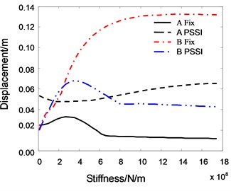
Fig. 20The relationship between roof acceleration and pounding stiffness
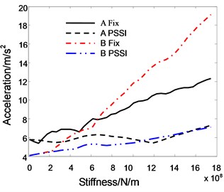
Fig. 20 shows the relationship between the peak acceleration of roof and the pounding stiffness. When the PSSI is not considered, the pounding accelerations of both A and B increase gradually with increasing pounding stiffness. When the PSSI of Structure A is considered, the influence of pounding stiffness is not obvious. It shows that the acceleration response of structure with smaller stiffness is sensitive to the pounding stiffness.
3.4. Influence of period ratio
If the periods of Structure A and B are and respectively, the period ratio is defined as . To investigate the influence of period ratio on the pounding of adjacent buildings, the stiffness of Structure A is scaled by coefficients. Thus the period ratio is changed by coefficients. Assuming that all other conditions remain unchanged, the curves of the maximum displacement and acceleration of roof floor varied with the period ratios are obtained as shown in Figs. 21-22.
From the figures it can be seen that the period ratio of adjacent buildings has a significant influence on the pounding response. As we know, the pounding of adjacent buildings is caused by their asynchronous vibration. When the period ratio approaches to 1, their vibrations are synchronous. Hence the buildings don’t collide with each other, and their responses are relatively small. When the period ratio approaches to 0.5, the displacement and acceleration response of Structure B are quite large. The maximum acceleration reaches 20 m/s2, and the maximum displacement reaches 0.3 m. It is perhaps because the vibration phases of two buildings are contrary in this case.
Fig. 21The relationship between roof acceleration and period ratio
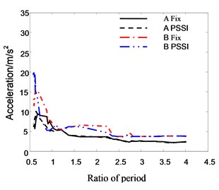
Fig. 22The relationship between roof displacement and period ratio
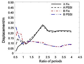
Fig. 23The relationship between the response factor of top floor in Structure A and inertia moment of pile section
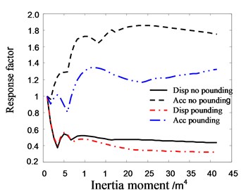
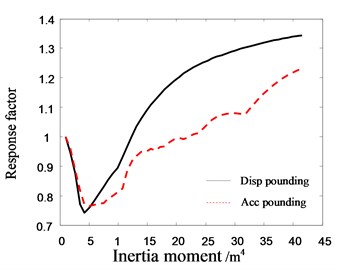
Fig. 24The relationship between the response factor of top floor in Structure B and inertia moment of pile section
3.5. Influence of pile stiffness
The stiffness of piles is one of the most important factors influence the PSSI. The response factor is defined as the ratio of structural response with different pile-cross-section to the response with pile-cross-section moment of inertia of 1 m4. Assuming that all other conditions remain unchanged, the relationship between the response factors in roof floor of structure and the pile-cross-section’s moment of inertia are computed.
Fig. 23 shows that as the increase of inertia moment, the displacement of Structure A decreases in the beginning and then stabilize gradually. The acceleration of Structure A increases in the beginning, and then approaches to constant. At the same time, the difference of response factors between pounding and no pounding increases gradually as the increase of inertia moment, which means the influence of pile inertia moment on pounding increases. The main reason is that the increase of pile inertia moment strengthens the global stiffness of structure and results in the exacerbation of structural pounding. It can be seen from Fig. 24 that the response of Structure B decreases sharply in the beginning, and then increases gradually as the increase of inertia moment. It also shows that the rigid pile can aggravate the pounding of adjacent building.
Fig. 25The relationship between the response factor of Structure A and velocity of shear wave
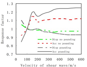
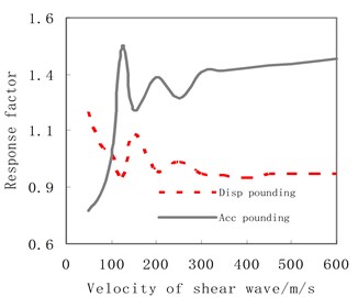
Fig. 26The relationship between the response factor of Structure B and velocity of shear wave
3.6. Influence of soil’s shear wave velocity
The types of construction sites can be classified by the equivalent shear-wave velocity and the layer thickness of soil. In order to investigate the influence of shear-wave velocity on the pounding, it is assumed that all other conditions remain unchanged and the ground is composed of a single soil type. The response factors, which is defined in this subsection as the ratio of peak responses with different soil to the response with the soil of shear-wave-velocity equaling 100 m/s, are obtained and shown in Figs. 25 and 26. It can be seen from Fig. 25 that if the pounding of structures happens, the peak roof acceleration of Structure A increases sharply with increasing of shear wave velocity initially. The increase rate reduces after the wave velocity reaches 200 m/s. When the wave velocity approaches about 400 m/s, the peak acceleration response tends to a constant value. Different from the acceleration response, the displacement of Structure A decreases with increasing of shear wave velocity at the beginning, and then the decrease rate reduces gradually. When the wave velocity approaches about 400 m/s, the peak displacement response almost remains unchanged. The reason is that the pounding responses depend on the stiffness of pounding systems. The larger the shear wave velocity of soil is, the bigger stiffness the pounding system has. Hence the pounding acceleration responses increases and the displacement response decreases with increasing of system stiffness. When the wave velocity approaches 400 m/s, the foundation of structure is nearly fixed. Thus its stiffness contribution to the system is almost unchanged. We can also see from Fig. 25 that if no pounding happens between adjacent buildings, the variation trends of acceleration and displacement as the increasing of wave velocity are similar to those of pounding cases, but the range of variation is smaller than that of pounding case. This observation shows that the free vibration responses of structure are more sensitive to soil than pounding responses.
Fig. 26 shows that the variation trends of pounding responses for Structure B is similar to that for Structure A, but the range of variation is much larger. For example, the displacement factor of Structure B is about 0.81 at velocity of 50 m/s and 1.51 at velocity of 150 m/s, while that of Structure A is 0.86 at velocity of 50 m/s and 1.22 at velocity of 150 m/s. The variation range of Structure B is more than twice of Structure A. The reason is that the stiffness of Structure B is smaller than Structure A. Hence, Structure B is more sensitive to PSSI than Structure A.
4. Conclusions
Although the influence of PSSI on vibration performance of a single building is not obvious, the influence of PSSI on the pounding of adjacent buildings is significant. PSSI can result in an increase of displacement response and a decrease of acceleration response to the flexible building, and a decrease of acceleration and displacement responses to the rigid building. The properties of soil and structures, such as shear-wave velocity of soil and stiffness of pile, play significant roles on the pounding of adjacent buildings. Therefore, the influence of PSSI can not be neglected during the design of separation distance between the adjacent buildings with pile foundation.
References
-
Vasiliadis L., Elenas A. Performance of school buildings during the Athens earthquake of 7 September 1999. Proceedings of the 12th European Conference on Earthquake Engineering, London, 2002, p. 264-267.
-
Rosenblueth E., Meli R. The 1985 earthquake: causes and effects in Mexico city. Concrete International, Vol. 8, 1986, p. 23-34.
-
Robert J. Earthquake-induced pounding between equal height buildings with substantially different dynamic properties. Engineering Structures, Vol. 30, 2008, p. 2818-2829.
-
Kasai K., Maison B. Building pounding damage during the 1989 Loma Prieta earthquake. Engineering Structures, Vol. 19, 1997, p. 195-207.
-
Li Y. M., Sun G. F. Dynamic interaction of pile-soil-frame structure. Journal of Building Struct., Vol. 23, Issue 1, 2002, p. 75-81, (in Chinese).
-
Muthukumar S., DesRoches R. A Hertz contact model with non-linear damping for pounding simulation. Earthquake Engng. Struct. Dyn., Vol. 35, 2006, p. 811-828.
-
Anagnostopoulos S. A. Earthquake induced pounding: state of the art. Proceedings of 10th European Conference on Earthquake Engineering, London, 1994, p. 897-905.
-
Maison B. F., Kasai K. Dynamics of pounding when two buildings collide. Earthquake Engng. Struct. Dyn., Vol. 21, 1992, p. 771-786.
-
Anagnostopoulos S. A., Spiliopooulos K. Y. An investigation of earthquake induced pounding between adjacent buildings. Earthquake Engng. Struct. Dyn., Vol. 21, 1992, p. 289-302.
-
Karayannis C. G., Favvata M. J. Earthquake-induced interaction between adjacent reinforced concrete structures with non-equal heights. Earthquake Engng. Struct. Dyn., Vol. 34, 2005, p. 1-20.
-
Wei X., Fan L. C., Wang J. J. Shake table test on soil-pile-structure interaction. Civil Engng. J., Vol. 35, Issue 4, 2002, p. 54-60, (in Chinese).
-
Lou M. L., Wang W. J., M H. C. Study on soil-pile-structure interaction system by shaking table model test. Journal of Tongji University, Vol. 29, Issue 7, 2001, p. 132-139, (in Chinese).
-
Lankarani H., Nikravesh P. A contact force model with hysteresis damping for impact analysis of multibody systems. Journal of Mechanical Design (ASME), Vol. 117, 1990, p. 354-374.
-
Zou L. H., Zhao R. D., Zhao J. C. Analysis of the response to earthquake of the pile-soil-isolated structure interaction. Journal of Geotechnical Engng., Vol. 26, 2004, p. 782-786, (in Chinese).
About this article
The support of the National Natural Science Foundation of China under Grant No. 51108091 is gratefully acknowledged.
