Abstract
A finite element approach to investigating the dynamic behavior of helical gear pairs (HGPs) by incorporating misalignment error and detail modifications of tip relief and face-width crowning is presented. Basing on the C code and derived tooth profile formulas, fine finite element models of helical gear pair (HGP) can be constructed parametrically. Also, all elements on the driven teeth surfaces are numbered to identify individual dynamic stresses. After analysis settings, the dynamic contact and fillet bending stresses of a theoretic HGP are first calculated. Then, the maximum stresses with misalignment error are also obtained. Finally, the effect of tooth modification on the dynamic stresses of HGPs with the misalignment errors is discussed. The result shows modification with tip relief and face-width crowning can reduce the dynamic responses caused by the impact contact of HGPs.
1. Introduction
Dynamic analyses of gears are required in the high precision, high speed, and low vibration applications. Still, to obtain gear dynamic responses is rather task even today owing that complicated considerations required such as numerous geometric design parameters, errors, manufacturing modifications, backlash, deformation, or even lubrication and wearing behaviors. Discrete models with equivalent mass, damping, and spring elements are the common approach. Only few of plentiful publications can be cited here [1-3]. Nevertheless, to pursue a deeper analysis or in multi physics coverage, discrete models hardly satisfy the sufficient requirements. Therefore, continuous geometric models are taken into consideration. One of which is detail geometric design is applied. Furthermore, with advancement of computing techniques, gear dynamics employing continuum models become attainable. Therefore, the works [4, 5] used commercialized finite element (FE) packages to find static stress and deformation of gears. Besides, using the dynamic stiffness method Huang et al [6] analyzed the tip displacement and fillet strain of a spur gear pair modeled by several non-uniform Timoshenko beams. Recently, continuum models were used in the other more gearing dynamic analyses [7, 8]. Fine element preparation of a HPG is a time consuming burden due to profile complexity, local sensitivity of contact points, modification, and errors. To obtain hexahedron elements of HGPs using tooth profile [9] and element creation for wide consideration were presented [10, 11] for gearing dynamics. Additionally, Yuksel and Kahraman [12] used an FE package to calculate the dynamic meshing forces of planetary gearing and predicted its wear on gear teeth.
Involute profile is sensitive to manufacturing and elastic errors. In practice, the negative behavior can be diminished by tooth modification. Generally, two kinds of modifications are often adopted which are applied in profile and face-with directions, respectively. A tip relief can also be viewed as the kind of profile modification to avoid tooth interference at initial contact of tooth pairs. Recently, a FE package for gears is being developing but analysis limitations remain [13]. Therefore, a FE approach using a general purpose FE software LS-DYNA is proposed here [14]. The dynamic behavior of HGPs including tip relief and crowning modifications is discussed.
2. Errors and modifications of gears
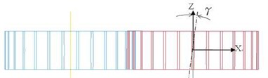
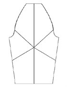
Assembly misalignment and tip interference are the very concern. Misalignment error causes edge teeth contact and makes the contact deviating from the theoretic conjugate relation. As shown in Fig. 1, angle is a misalignment error and is an angular error around -axis. Besides, tip interference happens at the moment when the mating tooth pair starts its surface contact. At that, the tooth tip of driven gear cannot understate its mesh for the conjugate tooth surface smoothly. Thus, extreme contact impact may occur.
Fig. 1A misalignment error of gear pair represented by angle γ
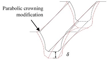
Modification is the method by applying deliberately adjusting tooth geometry to compensate the effect due to manufacturing and operation errors. Firstly, a parabolical crowning by applying the modification in the face-width direction can be defined by a crowning factor of as:
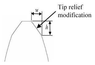
in which is the face-width, is the helical angle, and is a tool cutting depth for crowning. Then, a tip relief modification is used by relieving tooth thickness near tip region so as to smooth the tooth engagement especially at the instant of tooth meshing starting. As shown in Fig. 4(b), the pressure angle on a rack is related as:
which is the normal pressure gear of rack, is the amount of modification in the tangential direction, and is the modification in the profile direction. Fine detail tooth geometry can be determined by adjusting parameters , , and to meet design requirements.
Fig. 2Modifications of gear tooth: a) parabolic crowning; b) tip relief
a)
b)
3. Finite element models
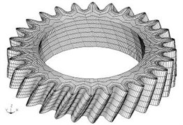
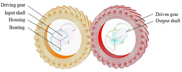
The process to tooth profile derivation and elements creation of a helical gear as shown in Fig. 3(a) are entailed in the previous work [11]. Only a briefing description is given in which a gear tooth is divided into several regular quadrilateral areas. There are six area blocks divided quadrilaterally shown in Fig. 3(b). By subsequently assigning the distances or numbers of nodes belonging to curves of the involute, fillet, tip relief, and other fractions, node distribution or density of the meshing elements can be conveniently adjusted. An example of created nodes is given in Fig. 3(c). Benefiting from the above process by using profile formula with a C code, the 3D meshing models can be effortlessly built using the above organized and regular nodes. Finally, all the element information helical gears can be shown using a preprocessor of LS-DYNA. Finally, the model of an HGP with crowning and tip relief modifications is obtained as shown in Fig. 4. The 3D element model of the gear pair is constructed using the following gear data as: normal module 3.175 mm, tooth number 28, normal pressure angle , helical angle 300, and face-width 30 mm.
Fig. 3Gear element generation: a) model of helical gear applying tip relief and crowning modifications, b) six blocks divided quadrilaterally, c) nodal distribution
a)
b)
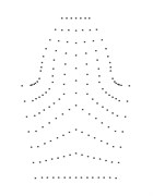
c)
Fig. 43D element model of a HGP with gears, shafts, and other components
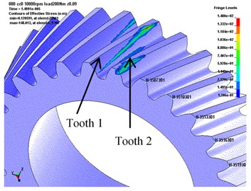
Using the FE model in Fig. 4 and assigning required inputs, gear dynamic response can be solved. Figure 5(a) shows dynamic stress distribution of the driven gear at an instant. In this study, two driven teeth will be discussed and noting them as tooth 1 and tooth 2. Actually, before dynamic response achieves a steady state, three leading teeth pairs have passed.
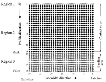
The dynamic stress of all elements on teeth is desired to investigate. Therefore, as shown in Fig. 5(b), all elements on an analysis tooth surface are expressed in an element matrix of 32 by 30 which is expressed along its profile and face-width, respectively. In the profile direction, the number is increasingly ordering from the tip to bottom. In the face-width direction, it is ordering along the face-width from the side of late mesh, called late side, to the other side called early side. The elements belong the matrix are categorized into three regions which are tip region, frank region, and fillet region shown in Fig. 5(b). At first, since the elements of the tooth tip, which are at the first row with blank circle, are tending to appear significantly large contact stress. Especially when no modification is used since the contact impact occurs caused by the tip interference. Therefore, the elements of tooth tip are separately depicted. The maximum contact stress almost occurs on this element. Besides, the second region is tooth face or flank which is the elements from row 2 to 23 illustrating with black circles. Then the third region is the gear fillet region from row 24 to 32.
In order to separately discuss the largest values of stresses, a symbol system is introduced. Then, in region 1 for the tooth tip, its largest dynamic stress for the first tooth pair is denoted as 1EA and is 2EA for the second tooth pair. When a tip relief modification is applied, this element is the first element at the start of active profile (SAP). Then for region 2, the maximum contact stress is denoted as 1E and 2E for tooth pair 1 and 2 respectively. For region 3 of the fillet stress section, 1R and 2R represent the maximum stress for tooth 1 and tooth 2 respectively.
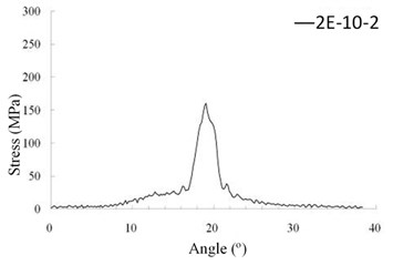
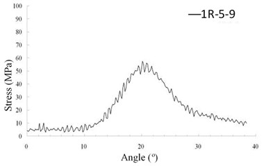
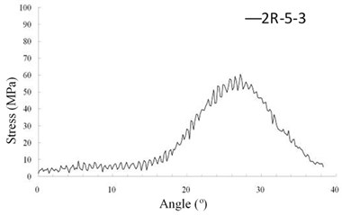
Finally, symbol representing the stresses of all elements on tooth surface of the two driven teeth can be attained. Exemplify an element numbered as “1EA-1-30”. The first symbol of “1EA” explains the element is belonging to region 1 (EA) on the first tooth (1); the second of “1” means the element is the first element along the profile direction from SAP; the 3rd symbol of “30” denotes it is the 30th element along the face-width direction. Accordingly, "1EA-1-30" indicates that the element locating in the tip region (region 1) for the first tooth pair of number 1 in the profile direction and number 30 in the face-width direction. Similarly, the element of “2E-10-2” identifies the element in the face or flank region (region 2) of the second tooth pair which is the 10th element from the tooth tip in the profile direction and is the 2nd element from the late side in face-width direction. Therefore, element “2R-5-9” is an element at the fillet region (region 3) on the second tooth of number 5 in the profile direction and number 9 in face-width direction.
Fig. 5a) 2 observed teeth on driven gear, b) element matrix of 32×30 for a tooth surface
a)
b)
4. Results and discussions
4.1. Stresses of a theoretic HGP
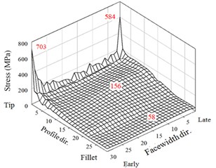
The dynamic stresses of a theoretic (no modification) HGP at 10000 rpm without misalignment error are firstly discussed. The gear data is the given for the model in Fig. 4. The behavior of two teeth pairs does not demonstrate entirely same in the dynamic analysis. Then, the von-Mises stresses of two adjacent tooth pairs are both exhibited. The dynamic contact and bending stresses of critical elements in the three regions of the two teeth are shown in Fig. 6. In addition, maxima of the dynamic stresses of the three regions are also 3D illustrated in Fig. 7 in which significant peaks are observed in the tooth tips.
The change of dynamic stresses of the driven gear for the first tooth pair during the meshing period is shown in Fig. 6(a). The maximum contact stress is 703 MPa which appears at the element of “1E-1-30” occurring at the rotation angle of 2° after the starting meshing of the first tooth pair contacting very near the early side of face-width. This largest contact stress peak is caused by the impact and singularly edging contact at the initial contact of the tooth pair during that the driven teeth tip may interfere with driving tooth flank due to the transmission error. Another significant large stress peak is 584 MPa on element “1E-1-1” at the rotation angle of 20°. The reason is similar to that at the angle of 2° but is not so shock impact. Even without considering manufacturing errors in HGPs, flexible deformation deviating the theoretically conjugating relation and inducing edge contact still cause significant tip interference.
Subsequently, dynamic contact stresses of the 1st tooth pair in the tooth flank surface (region 2) are discussed. In this region, the largest stress is 156 MPa which appears at element “1E-10-14” at the angle of 19.4°. The contact location of element “1E-10-14” is near the middle of face-width which is the near the highest point of leas tooth contact (HPSTC) and has the shortest action line. The dynamic contact stress of the element during the meshing period is expressed in Fig. 6(c). The final discussion of the 1st tooth is dynamic bending stresses at the tooth fillet in region 3. As shown in Fig. 6(e), the largest bending stress of the 1st tooth is 58 MPa appearing at element “1R-5-9” at the rotation angle 19.7° which is very close to the instant of HPSTC at which the maximum stress in the flank region abovementioned. The critical dynamic stresses of the 2nd tooth pair are also shown in Figs. 6(b), 6(d) and 6(f). Although the values between the two tooth pairs has obviously different, their changing tendency are alike. Also, the angle instants which the peaks occur are almost same.
Fig. 6The maximum bending stresses in a mesh period of theoretic HGP at 10000 rpm
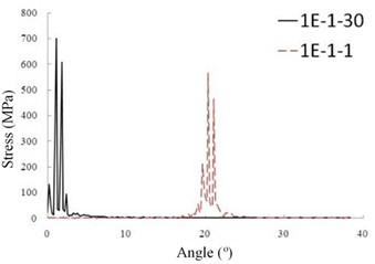
a) Tooth 1 (region 1)
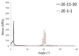
b) Tooth 2 (region 1)
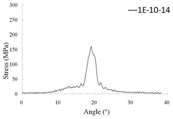
c) Tooth 1 (region 2)
d) Tooth 2 (region 2)
e) Tooth 1 (region 3)
f) Tooth 2 (region 3)
Fig. 7The maxima of dynamic stresses of theoretic HGP
a) Tooth 1 (all)
b) Tooth 2 (all)
5. Stresses of the theoretic HGP at misalignment error
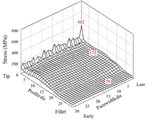
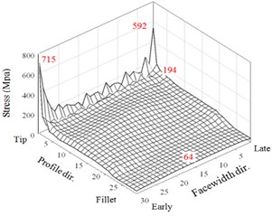
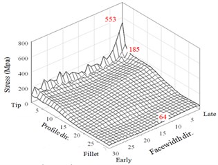
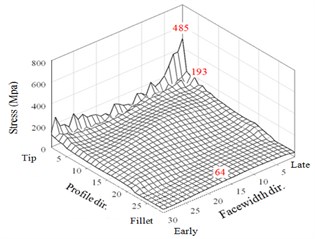
Next, the dynamic characteristics of a non-modification HGP at 10000 rpm under variant misalignment errors are discussed. Only 3D showing of their maxima for the dynamic contact and bending stresses in the three regions are 3D shown in Figs. 8(a) and 8(b).
The first case of a small misalignment 0.0053 is discussed. The HGP of a very small misalignment performs in a way similar to the results without misalignment error. There are rather large peaks appear right after the meshing starting and just before the ending. As noted in Fig. 10, the maximum stresses of the two driven teeth in the three regions of tooth tips, flanks, and fillets are 715, 194, and 64 MPa, respectively. Besides, the results of maximum stresses of the two larger misalignments are shown in Figs. 8(c)-8(f). For in Figs.10(c) and 10(d), the maximum stresses in the tooth tip, flank, and fillet regions are 533, 185, and 60 MPa, respectively. For 0.0214° in Figs. 8(e) and 8(f), they are 485, 206, and 70 MPa, respectively. Thus, the assigned misalignments do not significantly affect the maximum stresses on the frank and fillet regions except that tend to slightly increase the element stresses near the late sides. Noticeably, the maximum contact stresses are decreased with the increase of the assigned misalignment. It is surprised that the adequate misalignment can somewhat reduce impactive contact at the meshing starting for early side of the HGP. For example, it is from 703 MPa of perfect alignment HGP in Fig. 7(a) to 485 for 0.0214° in Fig. 8(e). However, the misalignment may complicate the non-modification HGP dynamic behavior. As the understanding, tooth contact pattern critically affects the dynamic transmission performance of gear systems. Therefore, variant modification techniques in the national or international standards have been established. All maximum values of the 3 regions of two driven teeth from the above analyses to the non-modification HGP considering the misalignment or not are summarized in Fig. 9 and show reduction effect of peak values of contact stress at a misalignment of 0.01374°.
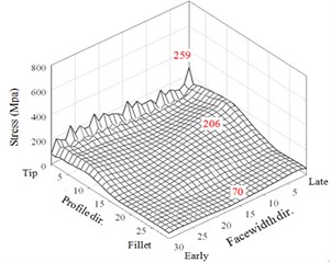
6. Stresses of HGPs applying modifications
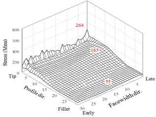
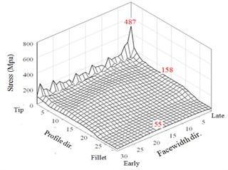
Finally, the dynamic stress of HGPs at 10000 rpm by both applying the tip relief and face-width crowning modifications are investigated. Respectively, the tip relief values are and in the profile and face-width directions formulated in Eq. (1) and the crowning factor 0.00002 in Eq. (2). The resulted maxima of dynamic surface contact stresses and fillet bending stresses of two driven teeth are shown in Fig. 10.
Fig. 83D illustration of maximum stresses of the two teeth with misalignment errors
a) Tooth 1 ( 0°, 0.0053°)
b) Tooth 2 0°, 0.0053°)
c) Tooth 1 ( 0°, 0.01374°)
d) Tooth 2 ( 0°, 0.01374°)
e) Tooth 1 ( 0°, 0.0214°)
f) Tooth 2 ( 0°, 0.0214°)
Fig. 9The maxima of dynamic stresses in Fig. 10 of the no modification HGP with misalignments
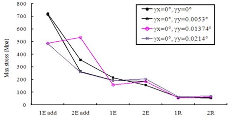
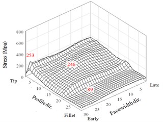
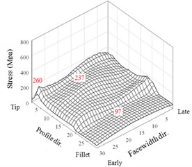
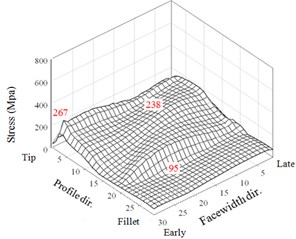
Fig. 103D illustration of maximum dynamic contact and bending stresses of two teeth for an HGP with various misalignment errors applied tip relief and crowning modifications
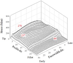
a) Tooth 1 ( 0°, 0.0053°)
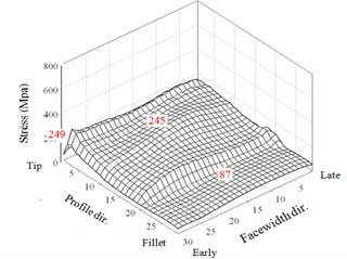
b) Tooth 2 ( 0°, 0.0053°)
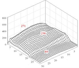
c) Tooth 1 ( 0°, 0.01374°)
d) Tooth 1 ( 0°, 0.01374°)
e) Tooth 1 ( 0°, 0.0214°)
f) Tooth 1 (0°, 0.0214°)
Fig. 11The maxima of dynamic stresses in Fig. 10 for the HGP of modification
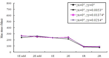
Comparing with the results of non-modification HGP shown in Fig. 8, it is observed that tip relief can effectively eliminate the very large peaks of tip contact stresses appearing at the instants near the meshing starting and ending of tooth pairs in Fig. 8. All the maxima of the dynamic contact and bending stresses of the two driven teeth in crowning HGPs are described below. For misalignment error 0.0053°, the maximum stresses in the tooth tip, face and flank, and fillet regions are 270, 237, and 89 MPa, respectively. In addition, they are 271, 231, and 86 MPa for 0.01374° and are 260, 237, and 96 MPa for 0.0214°, respectively. Comparing with the results of a non-modification in Fig. 8, Executing the tip relief and crowning modifications to the HGP has effectively decreased the flank contact and fillet bending stresses. The maximum contact stress at tooth tip is 62.1 % decreased from a value of 715 MPa to 271 MPa. Modifications with tip relief and face-width crowning can improve the impactive contact at the instants near the meshing starting and ending of tooth pairs. However, the maximum contact stresses on the tooth faces and flanks are increased from 206 MPa to 246 MPa, but not significantly. Finally, all the maximum values in this analysis to the HGP applying the tip and crowning modifications with and without considering misalignment errors are depicted in Fig. 11 and demonstrate a significantly better dynamic performance compared with the results in Fig. 9.
7. Conclusions
The dynamic behavior of surface contact and fillet bending stresses of HGPs including tooth modifications of tip relief and crowning are analyzed using an FE package. Numbering using an element matrix to identify critical maximum stresses is used. In addition to stress response history, the maxima of dynamic stresses in three regions on teeth surfaces are 3D illustrated. Even of no misalignment error, significant dynamic peaks of contact stresses of tooth pairs at the meshing start and end of a theoretic HGP are observed. It also exhibits dynamic responses of various tooth pairs in an HGP are not completely identical. Furthermore, dynamic characteristics of theoretic HGP considering various horizontal misalignment errors are discussed. Unexpectedly, certain misalignment may a little reduce impact contact at the moment of mesh starting of early side. Finally, design parameters for the tooth modifications are also given. The influences of the tip relief and crowning modifications on the dynamic stresses in HGPs with or without the assembly errors are investigated. Tooth modification with both tip relief and face-width crowning effectively improves the dynamic characteristics caused by impact contact of the HGP. An optimal study to facilitate tip relief and crowning modifications for spur and helical gear pairs incorporating the transmission errors will be further undertaken.
References
-
Yoon K., Rao S. S. Dynamic load analysis of spur gears using a new tooth profile. ASME J. Mech. Des., 118(1), 1996, p. 1-6.
-
Sfakiotakis V. G., Vaitsis J. P., Anifantis N. K. Numerical simulation of conjugate spur gear action. Comput. Struct., 79(12), 2001, p. 1153-1160.
-
Huang K. J., Wu M., Tseng J. T. Dynamic analyses of gear pairs incorporating the effect of time-varying lubrication damping. J. Vib. Control, 17(3), 2011, p. 355-363.
-
Chen Y. C., Tsay C. B. Stress analysis of a helical gear set with localized bearing contact. Finite Elem. Anal. Des., 38(8), 2002, p. 707-723.
-
Mažeika P., Didžiokas R., Barzdaitis V., Bogdevičius M. Dynamics and reliability of gear driver with antifriction bearings. Journal of Vibroengineering, 10(2), 2008, p. 217-221.
-
Huang K. J. Dynamic analyses of gear pairs with gross motion effect using a dynamic stiffness method. Proc. IMechE, Part K: J. of Multi-body Dynamics, 224(2), 2010, p. 203-210.
-
Parker R., Agashe G. V., Vijayakar S. M. Dynamic response of a planetary gear system using a finite element/contact mechanics model. ASME J. Mech. Des., Vol. 122, 2000, p. 304-310.
-
Litvin F. L., Lian Q., Kapelevich A. L. Asymmetric modified spur gear drives: reduction of noise, localization of contact, simulation of meshing and stress analysis. Comput. Meth. Appl. Mech. Eng., 188(1-3), 2000, p. 363-390.
-
Litvin F. L. Gear Geometry and Applied Theory. Cambridge U., N. Y., 2004.
-
Huang K. J., Su H. W. Approaches to parametric element constructions and dynamic analyses of spur/helical gears including modifications and undercutting. Finite Elem. Anal. Des., 46(12), 2010, p. 1106-1113.
-
Brauer J. A general finite element model of involute gears. Finite Elem. Anal. Des., 40(13), 2004, p. 1857-1872.
-
Yuksel C., Kahraman A. Dynamic tooth loads of planetary gear sets having tooth profile wear. Mech. Mach. Theory, 39(7), 2004, p. 695-715.
-
Prueter P., Parker R., Cunliffe F. A study of gear root strains in a multi-stage planetary wind turbine gear train using a three dimensional finite element/contact mechanics model and experiments. Proceedings of the ASME 2011, IDETC/CIE 2011, Washington, DC, 2011.
-
Hallquist J. O. LS-DYNA Theoretic Manual. LSTC Ltd., 1998.
About this article
