Abstract
Timber floors are prone to vibration due to the reduced modulus of elasticity of the material. Composite floors represent the most convenient solution to achieve acceptable performances and at the same time to save material and cost. In determining the natural frequency of a composite floor, the stiffness of the connection between the joined structural member is crucial. Inclined screws connections are characterized by the highest slip modulus among the mechanical fastener connections. However, the determination of the optimal inclination angle of the screws for vibration and deflection reduction remains an unexplored issue. The optimization problem is faced by means of an analytical model of beam on foundation.
Highlights
- The connection slip modulus depends on the screw inclination angle
- The natural frequency of a composite floor depend on the connection slip modulus
- Increments of natural frequency up to 35% can be achieved by varying the screw inclination angle
1. Introduction
Due to the lower density and stiffness, timber floors can exhibit greater flexibility than other construction materials leading to potential dynamic amplification of vibrations.
The low-frequency issues are related to the interaction with human activities (walking, running, e.g.), while the high-frequency ones mainly refer to the audio-frequency spectrum.
Excessive vibrations may cause a discomfort experienced by occupants, impact the performance of sensitive equipment and installations and even affect the usability of the space [1].
Composite floors might possess considerable advantages over traditional ones, including enhanced bending stiffness and dynamic response [2-4]. Often, a Cross-laminated-timber panel is added to existing joists and planking to retrofit existing floors. Cross-laminated timber panels are prefabricated solids slabs obtained by laminating together planks where adjacent layers are arranged at a right angle.
2. Problem formulation
Most of the serviceability verification proposed in literature are based on two sequential criteria. The first is stiffness based and the second is frequency-based [5].
If the deformability criterion is satisfied, the designer must also check that the first natural frequency of the floor is above a certain threshold , representing the limit between the resonant and the transient response. The human walking pace has a frequency of approximately 2 Hz. To account for the contribution of the higher harmonics, is typically prescribed by the standards as four times the walking frequency.
In designing practice, the floors are studied as simply supported beams. Their natural frequency vibration of a is given by the following well known equation:
where is the floor span and is the floor mass. For a composite floor, the flexural stiffness is determined from the mechanical and geometrical parameters of the joined members and of the connection between them:
where is the elastic modulus and and are the component section area and the component section moment of inertia respectively:
where and are the section heights of the members of the composite elements. As can be clearly seen from Eqs. (5) and (2), the effective flexural stiffness is strongly affected by the stiffness of the connection between members () and by the fasteners spacing (). Inclined screws connections are characterized by the highest slip modulus among the mechanical fastener connections [6]. However, the determination of the optimal inclination angle of the screws in layered product such as Cross-Laminated-Timber for vibration and deflection reduction remains an unexplored issue.
3. Connection stiffness model
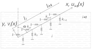
The behavior of the connection between component is reproduced via a model made of a beam on two layers of continuous elastic springs, one parallel and the other perpendicular to the sliding plane. The beam on elastic foundation model has been previously applied in [6] and is here extended to the case of screws inserted in layered products.
The field equations for each -th domain are:
where and are the axial and the transversal displacement of the -th domain, and represent the axial and flexural stiffness of the beam representing the screw. is the elastic modulus of the steel, is the section area and is the second moment of area:
where and represent the stiffnesses of the two layers of springs. The stiffness of the springs parallel to the sliding plane can be determined starting from the experimental foundation modulus deriving from embedment tests carried out parallel to the grain [6].
Fig. 1Analytical model representation
a) Subdivision into domains
b) Initial and deformed configuration of the beam representing the screw
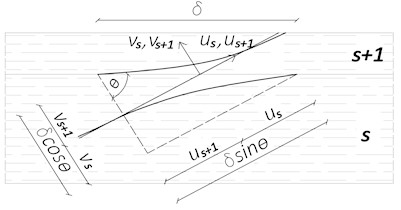
The point and the head of the screw are free and corresponding boundary conditions are described by Eqs. (9) and (12). To reproduce the relative sliding between members an internal distortion is applied to the beam on the sliding plane Eq. (10). The continuity between adjacent domains purposely introduced to account for different layer properties are ensured by Eqs. (11):
The slip modulus of the connection is given by the ratio between the component parallel to the sliding plane of the axial and shear forces of the beam and the internal distortion :
4. Validation
The model is validated on the results of standard push-out tests performed on two different configurations. The first with cross-laminated timber panel with its strong direction aligned to the underlying beam (Fig. 2(a)) and the second with cross-laminated timber panel with its weak direction aligned to the underlying beam (Fig. 2(b)).
The model proved to be accurate considering the high level of uncertainty that affect timber mechanical properties (Table 1).
Fig. 2Test setup and dimensions
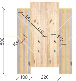
a) CLT strong direction
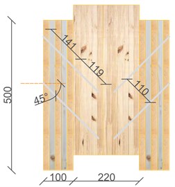
b) CLT weak direction
Table 1Comparison between experimental results and predicted values of the connection slip modulus
Configuration | Experimental slip modulus | Predicted slip modulus | Scatter |
CLT strong direction | 9.8 kN/mm | 10.8 kN/mm | 10.2 % |
CLT weak direction | 8.2 kN/mm | 10.0 kN/mm | 22.0 % |
Fig. 3 shows the internal forces of the screw in the two different configurations. Both shear and bending moment change sign into the cross laminated timber member due to the different stiffness properties of each layer.
Fig. 3Internal forces of the screw: CLT strong direction (black) and CLT weak direction (red)
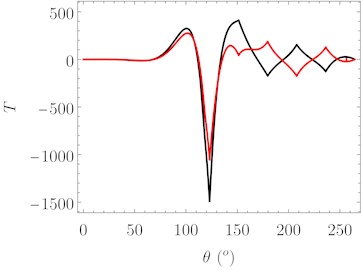
a) Shear
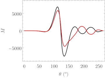
b) Bending moment
5. Optimization
The validated model is used to perform parametric studies on four different configurations: 3 layers CLT (orange circles), 5 layers CLT (blue squares), 7 layers CLT (red triangles) and 9 layers CLT (green diamons). First, the slip modulus of each of the four different configurations have been determined for varying inclination angle of the screw using the analytical model here presented (Eq. (13) and Fig. 4(a)). Then the bending stiffness of the resulting composite section has been determined according to Eq. (2). Finally, the natural frequency of the floor has been determined according to Eq. (1) and normalized with respect to the case with screw perpendicular to the sliding plane (Fig. 4(b)).
In all configuration an increase of connection slip modulus of up to 8 times of the slip modulus of a connection with a fastener perpendicular to the sliding plane is obtained (Fig. 4(a)). Corresponding increases in terms of composite floor natural frequency are shown in Fig. 4(b).
Fig. 4Slip modulus and natural floor frequency increase for varying screw inclination angle for the most common cross-laminated timber panel layouts
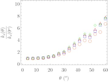
a) Normalized slip modulus of the connection
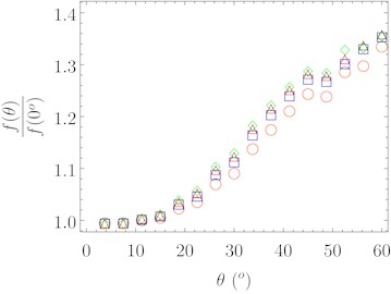
b) Normalized natural floor frequency
6. Conclusions
The dynamic behavior of composite floors made of cross-laminated-timber connected to other timber products via screws can be enhanced by inclining the fasteners. No study was found in literature dealing with the optimization of connections in layered product. In this paper an optimization is carried out using an analytical model of beam on foundation, capable of accounting for different layer orientation. A monotonic increase in natural frequency is observed. This is caused by the increased exploitation of the screw axial resisting contribution that lead to an increase in slip modulus and in effective stiffness.
References
-
A. Aloisio et al., “Vibration issues in timber structures: A state-of-the-art review,” Journal of Building Engineering, Vol. 76, p. 107098, Oct. 2023, https://doi.org/10.1016/j.jobe.2023.107098
-
P. G. G. D. Santos, C. E. J. Martins, J. Skinner, R. Harris, A. M. P. G. Dias, and L. M. C. Godinho, “Modal frequencies of a reinforced timber-concrete composite floor: testing and modeling,” Journal of Structural Engineering, Vol. 141, No. 11, Nov. 2015, https://doi.org/10.1061/(asce)st.1943-541x.0001275
-
K. Buka-Vaivade, D. Serdjuks, and L. Pakrastins, “Cost factor analysis for timber–concrete composite with a lightweight plywood rib floor panel,” Buildings, Vol. 12, No. 6, p. 761, Jun. 2022, https://doi.org/10.3390/buildings12060761
-
N. Vella, L. Gardner, and S. Buhagiar, “Experimental analysis of cold-formed steel-to-timber connections with inclined screws,” Structures, Vol. 24, pp. 890–904, Apr. 2020, https://doi.org/10.1016/j.istruc.2020.02.009
-
W.-S. Harris, R. Goldsmith, and T. Chang, “A new design method for timber floors – peak acceleration approach,” in International Network for Timber Engineering Research Meeting, 2018.
-
Y. de Santis and M. Fragiacomo, “Timber-to-timber and steel-to-timber screw connections: derivation of the slip modulus via beam on elastic foundation model,” Engineering Structures, Vol. 244, p. 112798, Oct. 2021, https://doi.org/10.1016/j.engstruct.2021.112798
About this article

The authors have not disclosed any funding.
The datasets generated during and/or analyzed during the current study are available from the corresponding author on reasonable request.
The authors declare that they have no conflict of interest.
