Abstract
This paper presents an analysis about the vibration reduction effects by a barrier in a nearly saturated soil medium. The barrier is assumed to consist in an arbitrary distribution of parallel cylindrical piles embedded in an infinite nearly saturated soil. Based on the equations governing the motion of nearly saturated soil, the complex wave numbers and amplitude ratios between the liquid phase and solid phase are first derived according to the Helmholtz decomposition theorem. With the aid of the Graff’s addition theorem, the unknown multiple complex scattering coefficients by an arbitrary configuration of piles as barriers are determined by taking an advantage of the boundary conditions at pile-soil interfaces and the linear independence of trigonometric functions. Then the corresponding expressions for the nearly saturated soil displacements at both sides of the pile rows can be obtained. The numerical results show that soil saturation degree and permeability exert significant influences on the isolation effectiveness of pile rows, and that the distance between neighboring rows is crucial for the isolation effectiveness. The isolation rules can provide useful guidelines to the design of pile rows as barriers in nearly saturated soil.
1. Introduction
Ground-borne vibrations are transmitted as waves generated by a variety of sources, such as pile driving, industrial machinery, construction blasting and traffic loads. Specifically, vibration in soft ground is an increasingly common geotechnical activity in many large cities. These vibrations often cause malfunctioning of sensitive machinery, measuring devices, discomfort to people and even lead some structures to be destroyed on their neighboring areas, which continue to challenge engineering research and practice and have received increasing attention in the recent years. Therefore, measures have to be taken to mitigate these vibrations. Rows of piles, installed in the soft soil between the vibration source and the receiver, offer a good alternative, especially when the radius of the isolating piles is comparable to the vibration wavelength.
Much work has been carried out on investigating barriers as a kind of vibration isolation system that can be used for reducing vibration amplitude. A large number of numerical studies about vibration isolation efficiency of pile rows and trenches in soils can be found in the literature. For example, Vanhoorickx et al. [1] used the topology optimization to design two-dimensional wave barriers embedded in an elastic half-space. The results show that the designs optimized for the frequency averaged insertion loss were sensitive to geometric imperfections. Avilés and Sánchez-Sesma [2] studied the scattering problem by a row of infinitely long piles in an elastic medium under incident elastic waves. Their results show that isolation barriers with stiff piles have a better screening effect than those with flexible ones. Boroomand and Kaynia [3] proposed an analytical model for the dynamic analysis of closely spaced piles under steady-state vertical vibrations and used it to demonstrate the problem of vibration isolation by piles. On the basis of a model replacing the row of piles with an effective trench, Kattis et al. [4] investigated the three-dimensional vibration isolation problem with the aid of the advanced frequency domain boundary element method. Their results show that open trenches or piles are more effective wave barriers than concrete filled ones. Kani and Hayakawa [5] addressed PC-wall piles as wave barriers for reducing ground vibration due to highway traffics; they found that the PC wall-pile barrier could reduce both surface and underground vibration by about 5 dB at a distance 25 m away from the footing of a bridge. By introducing the multi-scattering of electromagnetic waves, Xia et al. [6] put forward a new method to solve the problem of plane elastic wave scattering by an arbitrary configuration of piles. Based on the periodic theory of solid-state physics, Huang and Shi [7] proposed a new method for designing the pile barriers and performed an investigation on the mechanism of dynamic attenuation by using rows of piles. The results show that vibrations can be greatly reduced within the range of Frequency Band. Persson et al. [8] utilized a finite element to investigate the reduction in traffic-induced ground vibrations by the use of barriers. They found that infiltration of water could decrease the achieved reduction. Bordón et al. [9] used the two-dimensional numerical approach to analyze the vibration isolation analysis of thin-walled wave barriers in poroelastic soils. The results show that the efficiency of open trench-wall barriers could be evaluated neglecting their walls if they were typical sheet piles.
Besides numerical studies, both modeling tests and in-situ tests of trenches have been reported. Murillo et al. [10] conducted centrifuge modeling tests to simulate the vibrations generated by traffic and to investigate the efficiency of geofoam barriers. The results show that the isolation effectiveness of the system is mainly dependent on the barrier depth. Sivakumar Babu et al. [11] carried out field vibration tests to study the isolation effects, the results show that the proposed isolation systems with provisions of rubber mats as well as vertical cut-off trench is adequate for the range of vibrations expected from the vibrations of machines. More recently, Alzawi and Naggar [12] constructed a GeoFoam trench as a wave barrier, the results show that the GeoFoam barrier can be considered as a practical option for wave scattering and can effectively reduce the transmitted waves. Francois et al. [13] studied the dynamic soil characteristics and discussed the efficiency of a composite vibration isolating screen; they demonstrated that the stiffness contrast between the soil and the in-fill material is the key factor determining the performance of the screen. Dijckmans et al. [14] investigated the effectiveness of a sheet pile wall for reducing the railway induced vibration transmission. They found that the sheet pile wall reduced vibrations from 4 Hz upwards in a field test.
It is noted that although many problems involving vibration reduction have been considered, the studies are rather limited for dealing with the application of pile rows in nearly saturated soil for analysis of vibration reduction. Most of the existing works do not concern the practical influence of pore water in nearly saturated soil on the vibration reduction. Generally, there is under-ground water in the considered soil medium, and the existence of the water may affect to some extent, the propagation of waves in nearly saturated soil. The nearly saturated soil model superior to the elastic one is a good choice to be used for the analysis of vibration reduction by pile rows.
To examine the vibration reduction effect of pile rows as barriers in nearly saturated soil, there is a need to take into account realistic material parameters of the soil medium. The isolation model of pile rows as a barrier for in-plane shear waves in nearly saturated soil was proposed first. It was assumed that the piles had a circular cross section and were embedded in a homogeneous nearly saturated soil. The soil displacement field was determined by solving the unknown multiple scattering coefficients by an arbitrary configuration of piles with the aid of the Graff’s addition theorem and appropriate boundary conditions. The model validation was performed by a comparison of the numerical results with previous papers. In addition to that, a parametric study was conducted to investigate the effect of varying soil characteristic parameters and barrier geometry.
2. Governing equations for nearly saturated soil
With the displacement of the soil skeleton and the displacement of the pore fluid with respect to the soil skeleton in the Cartesian coordinate system, the coupled equations that govern the motion of a nearly saturated medium can be expressed as [15-17]:
where, , , , ; and are the Lame’s constants of the bulk material, is the porosity; , , in which , and are compression coefficients of soil grains, soil skeleton and pore fluid, respectively, is the saturation degree, is the pore fluid pressure; , in which , and are mass densities of soil grains, water and air, respectively; , is the acceleration of gravity and is the permeability coefficient of the medium; “” represents the derivative with respect to time.
The Helmholtz decomposition theorem allows one resolving the displacement fields as superposition of longitudinal and transverse vector components:
In the case of steady state, the time factor is shared by all the variables. Thus, omitting the time dependency, and substituting Eqs. (3) and (4) into the field Eqs. (1) and (2), two sets of coupled equations are obtained as:
where ; is the Laplacian operator.
The above Eqs. (5) and (6) may be manipulated to yield Helmholtz equations:
where in nearly saturated soil, , and designate the complex wave numbers of the fast longitudinal wave ( wave), slow longitudinal wave ( wave) and shear wave, respectively, which are given by:
where:
Employing Eq. (7), with some manipulations, the potentials , , and can be expressed as:
where the amplitude ratios , and between liquid phase and solid phase are given by:
3. Multiple scattering of in-plane shear waves by arbitrary configuration of piles
An arbitrary distribution of parallel cylindrical piles in nearly saturated soil is considered. In this nearly saturated soil, the fast longitudinal, slow longitudinal and shear waves propagate with phase velocities , and , respectively. The goal of this section is to determine the scattered wave fields by these piles when an in-plane harmonic shear wave is incident normal to the pile axis. When the length of the piles is infinite, the problem is then a two-dimensional one. denotes the center of the th pile, (, ) are the polar coordinates of with as origin. If is an observation point, its coordinate is (, ) in the coordinates system centered at .
Fig. 1Incident in-plane shear waves and reference systems for each pile
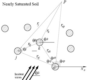
Consider an incident in-plane shear wave of amplitude , angular frequency , and incidence angle in a solid matrix, which propagates toward an arbitrary pile as shown in Fig. 1. Such an incident wave may be represented in the reference system (, ) attached to the pile as:
where ; is the wave number of shear waves; is the Bessel function of the first kind and order ; , is total pile numbers. It should be noted that the time factor has been omitted in the right-hand side of Eq. (13) and will be suppressed everywhere throughout the text for the sake of simplicity.
Since the polarized direction of particle movement of shear wave is perpendicular to the axis of the pile, its scattering becomes a plane problem. The coupling phenomenon would happen during the scattering process, and the scattered wave fields , and by piles will occur. According to the method of separation of variables, the scattered waves , and in the solid matrix by the th pile by employing the Fourier-Bessel series can be written as:
where and designate the complex wave numbers of the wave and wave, respectively; is the Hankel function of the first kind and order , representing an out-going wave that satisfies the Sommerfeld’s radiation condition at infinity; and , , , , and are complex coefficients to be determined from boundary conditions.
The total wave field in the solid matrix can be expressed as:
where , and represent the wave wave and shear wave by the th pile, respectively, which can be expressed in terms of the reference system (, ) attached to this pile.
The fluid potential function in saturated soil can be given by:
where ( 1, 2,3) represents the amplitude ratio between the fluid and solid potential functions.
If , with the aid of the Graff’s addition theorem, the Hankel function of Eqs. (14)-(16) can be transformed into a cylindrical coordinate system (, ):
According to Eqs. (17) and (18), the total wave fields in the solid matrix near the th pile can be rewritten as follows:
The displacement components of the skeletal frame and the fluid with regard to the solid and stress components in nearly saturated soil, by using the scalar potential functions , , and , can be derived as:
If the pile is considered as an elastic medium, then , . Thus, the calculation formula for wave numbers inside piles can be simplified as:
where and are the longitudinal and shear wave numbers inside the piles, is the Lame’s constant of piles, and and are the mass density and shear modulus of piles, respectively.
Since the pile is elastic, part of the incident waves are refracted by the pile surface and form a type of standing wave in the piles. The refracted waves inside the th pile can be given by:
where , , and are unknown coefficients to be determined from boundary conditions.
For the purpose of determining the unknown scattering coefficients, we assume that the piles and soils are perfectly bonded. In addition, the interfaces between the piles and soils are impermeable. Therefore, the boundary conditions can be represented as:
where , (1, 2,…, ); is the radius of the th pile.
Substituting the solid potential function Eqs. (17), (18) and the fluid potential function Eqs. (19), (20) into Eq. (24), the displacement and stress components of nearly saturated soil at each interface between the pile and soil can be obtained. Then taking into account the boundary conditions at the pile-soil interfaces and utilizing the linear independence of the trigonometric functions, ten infinite linear systems of algebraic equations in the unknown scattering coefficients can be derived:
where 1, 2,…, 5; 1, 2,…, ; ,…, 0, 1,…, ; - are coefficients associated with the Bessel function and the Hankel function.
Once the complex scattering coefficients through in the systems of Eqs. (32) and (33) are solved, the scattering wave field can be obtained. Then the total wave field can be determined. Thereafter the corresponding displacements of nearly saturated soil at both sides of the pile rows may be calculated.
4. Numerical analysis of isolation effectiveness
The material properties of soil are presented in Table 1, which are taken from Ref. [17] and Ref. [18]. For numerical calculation convenience, we assume that each pile is made of C20 concrete, which has a circular cross-section and has the same radius 1.0 m, the same Young’s modulus 2.55×10¹⁰ Pa, the same Poisson’s ratio 0.2 and the same mass density 2.4×10³ kg/m3. The number of piles 9. In addition to those, consider the case in which an incident in-plane shear wave of unit amplitude propagates normally to the direction , as illustrated in Fig. 2.
Table 1Material properties of nearly saturated soil
Parameters | Values |
Mass densities of soil grains | 2.65×10³kg·m-3 |
Mass densities of water | 1.0×10³ kg·m-3 |
Mass densities of air | 1.29 kg·m-3 |
Shear modulus of bulk material | 2.61×10⁷Pa |
Poisson’s ratio | 0.23 |
Porosity | 0.45 |
Compression coefficients of soil grains | 2.8×10⁻¹¹ Pa-1 |
Compression coefficients of pore fluid | 4.5×10⁻¹⁰ Pa-1 |
Compression coefficients of soil skeleton | 2.8×10⁻¹² Pa-1 |
Pore fluid pressure | 1.0×10⁵Pa |
Fig. 2Two rows of piles and rectangular coordinate system
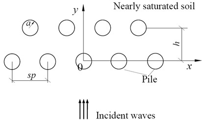
To evaluate the isolation effectiveness of the barrier system, the amplitude reduction ratio is introduced, which is the ratio of the displacement amplitudes at the point in the presence and in the absence of the barrier. Moreover, the Bessel expansion order is truncated at 8 so as to meet the accuracy.
It is noted that if the parameters , , , for the nearly saturated soil are assumed to tend to zero, the nearly saturated soil is reduced to a quasi-elastic medium. Additionally, when the distance is assumed to be 0, the double rows become a single one. In order to verify the accuracy of the present solution scheme, a comparison with existing solutions for isolation problems of elastic waves is presented. It can be observed from Fig. 3 that the numerical results of this study are close to those of Avilés and Sánchez-Sesma [2].
Fig. 3Comparative study of obtained results
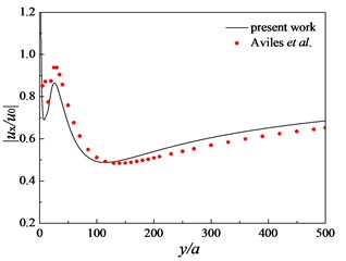
Fig. 4Meshing diagram
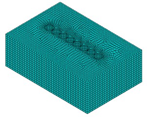
Fig. 5Comparison of present solutions and FEM solutions
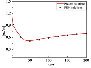
Another validation was performed using a finite element software called Open Sees, which was an open system for vibration simulation provided by the Pacific Earthquake Engineering Research Center [19]. There were 32896 elements in the model (see Fig. 4). Eight-node hexahedral element Brick UP was implemented for the nearly saturated soil. Each node had 4 degrees-of-freedom (DOF): DOFs 1 to 3 for solid displacement and DOF 4 for fluid pressure. The corresponding material was Fluid Solid Porous Material which coupled the responses of two phases: fluid and solid. Eight-node brick element stdBrick was implemented for the concrete pile. The use of ND Material Elastic Isotropic was made as the corresponding material. To eliminate the spurious reflections of radiating waves, the classical viscous boundary condition was used. A time-harmonic shear wave of unit amplitude which propagated normally to the row of piles was taken as the excitation strategy. The following parameters for pile and soil were used in the FEM simulation: 2.55×10¹⁰ Pa, 2.4×10³ kg/m3, 0.2, 8, 2.0 m, 0, 1.0, 10-9 m/s. Other parameters for simulation were the same as those in Table 1. It can be seen from Fig. 5 that excellent agreement is noted between the two solutions.
Fig. 6 displays the variation of amplitude reduction ratio along the dimensionless distance before and after the rows of piles for 16 Hz. As seen in the figure, the amplitudes of soil will fluctuate dramatically at the area close to the pile rows. In front of the barrier, the amplitudes of soil are magnified after the pile installation. However, in the presence of the pile rows, the figure also clearly reveals a considerable reduction of amplitude in a wide area behind the barrier, which indicates that the pile rows perform like a unit instead of a set of independent piles.
Fig. 6Variation of amplitude reduction ratio near pile rows: f=16 Hz, Sr=1.0, kd=10-9 m/s, sp=3.0 m, h=2.5 m
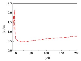
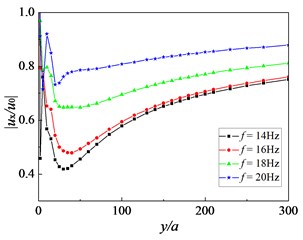
Fig. 7Influence of frequency of incident waves on amplitude reduction ratio: Sr=1.0, kd=10-9 m/s, sp=3.0 m, h=2.5 m
In the following, the influence of certain parameters, such as the frequency of incident waves and intrinsic permeability of nearly saturated soil, on the isolation effectiveness of pile rows is investigated.
Fig. 7 shows the amplitude reduction ratio as a function of the dimensionless distance for the exciting frequencies of 14, 16, 18 and 20 Hz behind the pile rows. It can be seen from the figure that the amplitude reduction ratio changes greatly as the dimensionless distance from the pile rows is less than 200. Moreover, the minimum value of the amplitude reduction ratio decreases and the optimum isolation range moves back away from the pile rows as the frequency decreases, and the isolation effectiveness of the pile rows is improved. For the cases considered, the pile rows reduce the amplitude reduction ratio 0.52 when the exciting frequency is 16 Hz. It is also concluded that the isolation effectiveness of pile rows is sensitive to the exciting frequency of incident waves.
Fig. 8 presents the influence of the saturation degree on the isolation effectiveness of the pile rows. It can be observed that the isolation efficiency of pile rows is optimal when the saturation degree 1.0. At the meantime, the amplitude reduction ratio shows some instability when the saturation degree varies from 0.95 to 0.8. The cause might be that the water content in soil reduces when the saturation degree decreases, and the propagation path for and waves in this kind of soil is more complex than that in the saturated soil, which also affects the amplitude reduction ratio of pile rows.
The influence of soil permeability on the isolation effect of the pile rows is examined next. The permeability coefficient of nearly saturated soil takes the following different values: 1.0×10⁻⁵m/s, 1.0×10⁻⁷m/s, 1.0×10⁻⁹m/s, 1.0×10⁻¹⁰m/s and 1.0×10⁻¹¹m/s. All the other parameters for the nearly saturated soil, the incident waves and pile rows assume the same values as above. The variation of the amplitude reduction ratio for different values of the soil permeability coefficient is given in Fig. 9. The minimum amplitude reduction ratio reduces when the permeability of soil decreases, and the isolation efficiency of pile rows would get better. The reasons for this are as follows. When the soil permeability is low, such as silt, the wave in nearly saturated soil will play an important role. While the soil permeability is high, such as fine sand, the wave in nearly saturated soil will play an important role.
The pile spacing between neighboring piles is an important parameter for the barrier design of vibration isolation by rows of piles. Fig. 10 plots the variation of the amplitude reduction ratio versus for the cases of the pile spacing 2.5 m, 3.0 m, 3.5 m, 4.5 m and 5.5 m, respectively. As the pile spacing decreases, the distance between neighboring piles reduces. Since there are three kinds of waves ( wave, wave and shear wave) in nearly saturated soil during the wave propagation process, the multiple scattering effect among piles will become much stronger. The isolation effectiveness of pile rows for 2.5 is better than that for 5.5.
Fig. 8Influence of saturation degree on amplitude reduction ratio: f=16 Hz, kd=10-9 m/s, sp=3.0 m, h=2.5 m
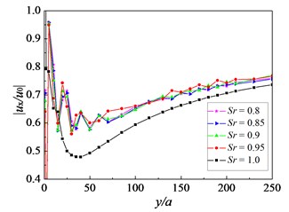
Fig. 9Influence of soil permeability on amplitude reduction ratio: f=16 Hz, Sr=1.0, sp=3.0 m, h=2.5 m
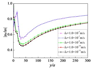
Fig. 10Influence of pile spacing on amplitude reduction ratio: f=16 Hz, Sr=1.0, kd=10-9 m/s, h=2.5 m
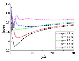
Fig. 11Influence of distance between two neighboring rows on amplitude reduction ratio: f=16 Hz, Sr=1.0, kd=10-9 m/s, sp=3.0 m
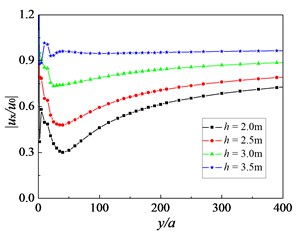
Fig. 12Contour of amplitude reduction ratio for two rows of piles as isolation barrier: f=16 Hz, Sr=1.0, kd=10-9 m/s, sp=3.0 m, h=2.5 m
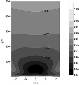
Fig. 11 illustrates the impact of the distance between two neighboring rows on the isolation effectiveness by double-row piles. The minimum value of amplitude reduction ratio increases with the increase of distance . The isolation efficiency of double-row piles would get worse. This is because the distance between two rows of piles is so far that the pile rows behave like two sets of independent obstacles. The multiple scattering effect between these two rows of piles will become weak. In other words, the row number will have an important influence on the isolation efficiency of the barrier. In order to get better isolation effectiveness for two rows of piles, it requires choosing an optimal distance between two rows of piles.
To give a clearer picture of the isolation phenomenon, Fig. 12 shows a contour diagram of the amplitude reduction ratio behind the pile rows. The figure depicts the situation of the isolation area and shows that with the distance behind the pile rows enlarged, the adjoining isolines get farther to each other. Obviously, the isolation effectiveness increases firstly, then diminishes from the centerline (). Furthermore, the optimal isolation position occurs at the center of the screened zone, which means that the isolation effectiveness at the center of the screened zone is better than that at the edge.
5. Conclusions
The performance of a protective barrier is a key issue in the design of civil environment engineering. This paper focuses on the vibration isolation by pile rows in nearly saturated soil. The effect of pile rows in nearly saturated soil on wave scattering is explored analytically. Then, the influence of a few parameters such as soil saturation degree and permeability on the isolation effectiveness is numerically investigated and discussed. Based on the present work, the following general conclusions may be drawn:
1) Soil saturation degree exerts significant influence on the isolation effectiveness of the pile rows. A larger saturation degree of soil can preferably attenuate the energy of incident waves, which might result in better isolation effectiveness for the pile rows.
2) Soil permeability is also a vital factor affecting the isolation effectiveness. Decrease of the soil permeability coefficient will enhance the isolation effectiveness in the area behind the pile rows.
3) The distance between neighboring rows is crucial for the isolation effectiveness. Generally, decreasing the distance between neighboring rows in the appropriate range can achieve better isolation effectiveness.
4) The isolation effectiveness at the center of the screened zone is different from that at the edge, the optimal isolation position occurs at the center of the screened zone.
References
-
Vanhoorickx C., Sigmund O., Schevenels M., Lazarov B. S., Lombaert G. Topology optimization of two-dimensional elastic wave barriers. Journal of Sound and Vibration, Vol. 376, Issue 8, 2016, p. 95-111.
-
Avilés J., Sánchez-Sesma F. J. Piles as barriers for elastic waves. Journal of Geotechnical Engineering, Vol. 109, Issue 9, 1983, p. 1133-1146.
-
Boroomand B., Kaynia A. M. Vibration isolation by an array of piles. International Conference on Soil Dynamics and Earthquake Engineering, Karlsruhe, Germany, 1991, p. 683-691.
-
Kattis S. E., Polyzos D., Beskos D. E. Modelling of pile wave barriers by effective trenches and their screening effectiveness. Soil Dynamics and Earthquake Engineering, Vol. 18, Issue 1, 1999, p. 1-10.
-
Kani Y., Hayakawa K. Simulation analysis about effects of a PC wall-pile barrier on reducing ground vibration. Proceedings of the International Offshore and Polar Engineering Conference, Honolulu, HI, United States, 2003, p. 1224-1229.
-
Xia T. D., Sun M. M., Chen C., Chen W. Y., Xu P. Analysis on multiple scattering by an arbitrary configuration of piles as barriers for vibration isolation. Soil Dynamics and Earthquake Engineering, Vol. 31, Issue 3, 2011, p. 535-545.
-
Huang J. K., Shi Z. F. The application of periodic theory to rows of piles for horizontal vibration attenuation. International Journal of Geomechanics, Vol. 13, Issue 2, 2013, p. 132-142.
-
Persson P., Persson K., Sandberg G. Numerical study of reduction in ground vibrations by using barriers. Engineering Structures, Vol. 115, Issue 5, 2016, p. 18-27.
-
Bordón J. D. R., Aznárez J. J., Maeso O. Two-dimensional numerical approach for the vibration isolation analysis of thin walled wave barriers in poroelastic soils. Computers and Geotechnics, Vol. 71, Issue 1, 2016, p. 168-179.
-
Murillo C., Thorel L., Caicedo B. Ground vibration isolation with geofoam barriers: Centrifuge modeling. Geotextiles and Geomembranes, Vol. 27, Issue 6, 2009, p. 423-434.
-
Sivakumar Babu G. L., Srivastava A., Nanjunda Rao K., Venkatesha S. Analysis and design of vibration isolation system using open trenches. International Journal of Geomechanics, Vol. 11, Issue 5, 2011, p. 363-369.
-
Alzawi A., Hesham EI. Naggar M. Full scale experimental study on vibration scattering using open and in-filled (GeoFoam) wave barriers. Soil Dynamics and Earthquake Engineering, Vol. 31, Issue 3, 2011, p. 306-307.
-
Francois S., Schevenels M., Thyssen B., Borgions J., Degrande G. Design and efficiency of a composite vibration isolating screen in soil. Soil Dynamics and Earthquake Engineering, Vol. 39, 2012, p. 113-127.
-
Dijckmans A., Ekblad A., Smekal A., Degrande G., Lombaert G. Efficacy of a sheet pile wall as a wave barrier for railway induced ground vibration. Soil Dynamics and Earthquake Engineering, Vol. 84, Issue 5, 2016, p. 55-69.
-
Biot M. A. Theory of propagation of elastic waves in a fluid-saturated porous solid. Part I: Low-frequency range; Part Ⅱ: High-frequency range. Journal of the Acoustical Society of America, Vol. 28, Issue 2, 1956, p. 168-178.
-
Biot M. A. Mechanics of deformation and acoustic propagation in porous media. Journal of Applied Physics, Vol. 33, Issue 4, 1962, p. 1482-1498.
-
Vardoulakis I., Beskos D. E. Dynamic behavior of nearly saturated porous media. Mechanics of Materials, Vol. 5, 1986, p. 87-108.
-
Stoll R. D., Kan T. K. Reflection of acoustic waves at a water-sediment interface. Journal of the Acoustical Society of America, Vol. 70, Issue 1, 1981, p. 149-156.
-
Jeremic B., Zhao C., Taiebat M., Dafalias Y. Numerical simulation of fully saturated porous materials. International Journal for Numerical and Analytical Methods in Geomechanics, Vol. 32, Issue 13, 2008, p. 1635-1660.
About this article

The work presented in this paper is supported by the National Natural Foundation of China (No. 51578425, 51108349, 51622810), the National Key Research and Development Program of China (No. 2016YFC0800201) and the State Scholarship Fund of China.
