Abstract
An iron alloy coating with gradient transition was sprayed on F304 stainless steel substrate by plasma spraying method and with a gradient material obtained by the material performance simulation software, and the effect of gradient transition on the microstructure, hardness and wear resistance of the coating was analyzed by comparing with the non gradient transition coating. The results show that both the gradient coating and the non gradient coating have wavy layered structure and are formed by highly flattened deformed particles overlapping each other. Micro metallurgical bonding was observed between the coating particles, and oxides were observed between the coating and the substrate, between the flat particles and inside the flat layer. The coating microstructure includes austenite phase, ferrite phase and carbides. The surface hardness of the gradient coating and the non gradient transition coating are basically similar, but there are obvious steep drop steps between the section hardness of the non gradient coating and the substrate hardness, while the section hardness of the gradient coating and the substrate hardness change gently, and the section hardness of the gradient coating is slightly lower than that of the non gradient coating. The wear rate of gradient coating is similar to that of non gradient coating at 400 °C, but it is lower than that of non gradient transition coating at 350 °C. The reason for reducing hardness changes and improving wear resistance of the coating may be related to the improvement of the microstructure and plasticity of the coating by the gradient layer, but more research is needed.
Highlights
- The surface hardness of transition coating with gradient is similar to that of transition coating without gradient, both are about 490HV, but the cross-section hardness of transition coating without gradient is significantly higher than that of transition coating with gradient.
- There is a steep decrease in hardness between the non gradient transition coating and the substrate, while the change in hardness between the cross-section of the gradient transition coating and the substrate is gentle.
- The wear rate of transition coatings with gradient transition and without gradient transition coating is similar at 400°C, but at 350°C, the wear rate of gradient transition coating is slightly lower than that of no gradient transition coating.
1. Introduction
The sealing surface of third-generation nuclear power nuclear grade valves is widely used to replace Stellite alloy with iron based alloy to reduce radiation dose during maintenance of nuclear power units. However, during manufacturing and operation, a large number of welding cracks and brittle cracks have occurred on the sealing surface of iron based alloys. The reasons are mainly related to the welding defect and thermal stress during the manufacturing and operation of the sealing surface [1-5]. The valve sealing surface is one of layered structure. In order to regulate the structure, performance, and stress of the layered structure, gradient transition methods have been developed [6, 7] and applied to molds, rollers, high-temperature boiler tubes, hydrogenation reactors, and other components [8-12]. In order to solve the problem of welding cracks on the iron based alloy sealing surface of nuclear grade valves, this paper evaluated and selected several gradient materials for valve sealing surface through material performance simulation calculation software in the previous studies. In this paper, based on these gradient materials, the sealing surface with gradient transition is prepared by plasma spraying, and compared with the structure and performance of the non gradient transition sealing surface, in order to obtain the structure and performance behavior of the gradient transition valve sealing surface.
2. Test method
2.1. Gradient materials
In the preliminary calculation of this paper, Norem02 alloy, a typical iron-based alloy material for nuclear-grade valves, and F304 stainless steel, a valve material, were selected as calculation materials. The two material compositions are shown in Table 1. Using JMatPro software, the equilibrium phase, carbide, characteristic parameters (density, linear expansion coefficient, thermal conductivity, Young's modulus, Poisson's ratio and specific heat capacity) and Physical and chemical properties (strength, hardness). According to the evaluation, the two mixtures of 30%F304+70%Norem02 and 60%F304+40%Norem02 can be used as candidate gradient materials. Mix F304 and Norem02 powders prepared in proportion, and grind them in a ball mill for 16 hours to obtain a mixture with a particle size of 50 mesh as the test material. The composition of the test materials is shown in Table 2.
Table 1Chemical composition of Norem02 Alloy and F304 Stainless Steel (wt,%)
Material | C | Mn | Si | Cr | Ni | N | Mo | Fe |
Norem02 | 1.23 | 4.30 | 3.38 | 25.40 | 4.00 | 0.17 | 2.00 | Bal. |
F304 | 0.08 | 2.00 | 0.75 | 18.00 | 8.00 | 0.10 | 0.00 | Bal. |
Table 2Spray powder and their composition
Spray powder number | Proportion (%) | Chemical composition (%) | ||||||||
F304 | Norem02 | C | Mn | Si | Cr | Ni | N | Mo | Fe | |
F0 | 0 | 100 | 1.23 | 4.30 | 3.38 | 25.40 | 4.00 | 0.17 | 2.00 | Bal. |
F3 | 30 | 70 | 0.89 | 3.61 | 2.59 | 23.18 | 5.20 | 0.15 | 1.40 | Bal. |
F6 | 60 | 40 | 0.54 | 2.92 | 1.80 | 20.96 | 6.40 | 0.12 | 0.80 | Bal. |
2.2. Coating preparation
APS-3000K plasma spraying machine is used to spray coating on F304 stainless steel base material with thickness of 6 mm. The coating arrangement is shown in Fig. 1. The F000 sample does not contain a gradient layer and all use Norem02 powder. F330 contains one gradient material F3, and F630 contains two gradient materials F6 and F3. Before spraying, the surface of the substrate is first degreased, and then the surface is roughened by sandblasting. Spray current is at 450 A, spray voltage 60 V, spray distance 110 mm, powder feeding speed 25 g/min, the main gas flow rate 40 L/min, and the gas pressure 0.6 MPa, the secondary air flow rate 1.0 L/min and the gas pressure 0.6 MPa. The single layer thickness of the coating is 0.2 mm, and each sample is sprayed with 3 layers, with a total coating thickness of 0.6 mm. The morphology of the actual prepared sample is shown in Fig. 2.
3. Test results and analysis
3.1. Microstructure observation
A fast-moving wire electric discharge cutting machine was used to cut the sample for microstructure observation perpendicular to the scanning direction of the sprayed layer. After the samples were ground and polished, the chemical wetting method was used to display the structure, using aqua regia as the substrate etchant, and nitric acid solution as the coating etchant. A Zeiss Axio Observer A3 inverted microscope and a Zeiss Sigma 300 field emission scanning electron microscope were used to observe the microstructure, and a Rigaku Rapid IIR micro-area XRD diffractometer was used to analyze the phase.
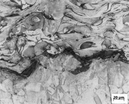
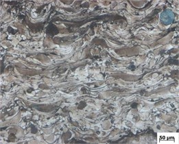
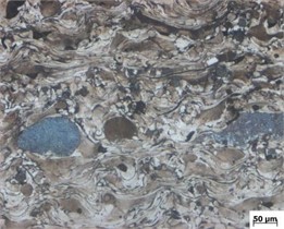
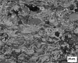
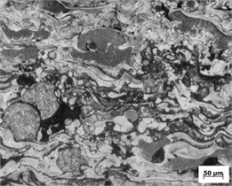
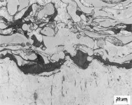
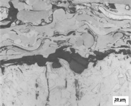
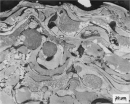
The cross-sectional morphologies of F000, F330 and F630 coatings are shown in Fig. 3, Fig. 4 and Fig. 5, respectively. The coating has a wavy layered structure as a whole, consisting of highly flattened deformation particles overlapping with each other. There is a micro-metallurgical combination between the coating particles, the particles are basically spread out, and the coating is relatively dense.
Fig. 1Coating layout and sample number
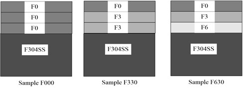
Fig. 2Morphology of sprayed sample
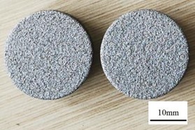
Fig. 3Microstructure of F000 sample
a) Fusion line area
b) Second layer
c) Third layer
Fig. 4Microstructure of F330 sample
a) Fusion line area
b) Second layer
c) Third layer
Fig. 5Microstructure of F630 sample
a) Fusion line area
b) Second layer
c) Third layer
There is a relatively obvious black substance between the substrate and the first layer of coating (Fig. 3(a), Fig. 4(a), Fig. 5(a)), and there are also small black oxides between the coatings (Fig. 3(b), Fig. 4(b), Fig. 5(b)). Energy spectrum analysis shows that they are iron oxides. Although the surface of F304 was sandblasted before spraying, during the spraying process, part of the oxide is involved in the interior of the particle during the particle surface and internal convection, while another part of the oxides gathered and solidified on the particle surface to form a thin oxide layer. The molten particles mixed with oxides spread and solidify on the substrate, forming coatings containing oxide inclusions between flat particles and within the flat layer. There are still a small amount of incompletely melted raw material powder in some coatings (Fig. 3(c), Fig. 5(c)). These powders have insufficient deformation and are in an unmelted (Fig. 5(c)) or semi molten state.
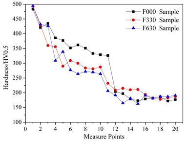
3.2. Hardness measurement and analysis
The hardness measurement was conducted using the MH-5 digital microhardness tester, and the measurement results are shown in Fig. 6. Among them, measuring point 1 is located on the spraying surface, and measuring points 2 to 20 are located on the vertical cross-section of the coating. Measure point 2 at a distance of 50um from the coating surface, and measure every 50 um thereafter. From Fig. 7, it can be seen that the surface hardness of the coating is significantly higher than that of the coating cross-section. When there is no gradient transition material (F000 sample), there is a sharp decrease in hardness between the coating and the substrate, while when gradient materials are used, the difference in hardness between the coating and the substrate is significantly reduced. Comparing the gradient transitions of F3+F3 and F6+F3, the hardness of the F330 transition layer is slightly higher than that of F630.
The hardness of the coating cross-section is related to the type and quantity of carbides in the coating. During the preliminary simulation calculation, the content of carbides in F3 was significantly higher than that in F6. Under the same other conditions, the carbide content was the reason why the hardness of the F330 gradient layer was slightly higher than that of F630.
Fig. 6Hardness measurement results of different deposited layers
3.3. Wear resistance test
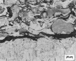
Conduct high-temperature wear test using HT-1000 high-temperature friction and wear testing machine. The test time was 30 min, the rotation speed was 64.9 r/min, the friction track radius was 3.5 mm, and the load was 15 N. The sample was heated from room temperature to 350 °C and 400 °C for 7 minutes and 8 minutes, respectively, before entering the insulation stage. For SiN balls with a diameter of 6.0mm, there is no lubrication. The wear rate is calculated according to Eq. (1):
where: – wear rate, mm3/ (N·m); – riction load, N; – wear volume, mm3; – friction distance, mm.
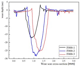
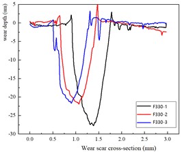
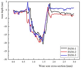
The friction and wear results shown in Fig. 7. Fig. 8 are the cross-sectional profile of the friction and wear track of the sample at 400 °C high temperature. From Fig. 7 and Fig. 8, it can be seen that at 400 °C, the wear rate of coatings containing gradient materials is similar to that of coatings without gradient materials; At 350 °C, the wear rate of non gradient coatings is slightly lower than that of coatings with gradient transitions. It shows that the wear resistance of the coating can be improved after the gradient coating is adopted. According to literature [8], the abrasion resistance of plasma spraying coating is not only related to the macro hardness, but also related to the plasticity, brittleness and cohesive strength of the coating. A coating with a good combination of toughness and brittleness has higher wear resistance. The mechanism by which this gradient material affects the wear resistance of the coating is a topic that needs to be studied in the future.
Fig. 7High temperature friction and wear test results
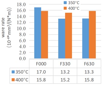
Fig. 8Cross-sectional profile of worn track at 400 °C
4. Conclusions
There is no significant difference in the morphology of the coatings with gradient transition and without gradient transition, and both have a wavy layered structure as a whole, which is composed of highly flattened deformed particles overlapping each other. There is a micro-metallurgical combination between the coating particles, the particles are basically spread out, and the coating is relatively dense. Oxide can be observed between the coating and the substrate, between the flat particles and inside the flat layer. The phases in the coating include austenite phase, ferrite phase and carbides.
The surface hardness of transition coating with gradient is similar to that of transition coating without gradient, both are about 490 HV, but the cross-section hardness of transition coating without gradient is significantly higher than that of transition coating with gradient. There is a steep decrease in hardness between the non gradient transition coating and the substrate, while the change in hardness between the cross-section of the gradient transition coating and the substrate is gentle.
The wear rate of transition coatings with gradient transition and without gradient transition coating is similar at 400 °C, but at 350 °C, the wear rate of gradient transition coating is slightly lower than that of no gradient transition coating. The mechanism of this phenomenon may be related to the improvement of the plasticity and strength of the coating by the gradient layer, but more research is needed.
References
-
K.-C. Tsai, S.-L. Jeng, and J.-Y. Huang, “Prevention of delayed cracking of iron based hardfacing welds,” Engineering Failure Analysis, Vol. 48, No. 2, pp. 210–217, Feb. 2015, https://doi.org/10.1016/j.engfailanal.2014.11.025
-
Z. Que, M. Ahonen, I. Virkkunen, P. Nevasmaa, P. Rautala, and H. Reinvall, “Study of cracking and microstructure in Co-free valve seat hardfacing,” Nuclear Materials and Energy, Vol. 31, No. 6, p. 101202, Jun. 2022, https://doi.org/10.1016/j.nme.2022.101202
-
W. Zhu et al., “Analysis and improvement of cracking in ironbase alloy hardfacing layer,” (in Chinese), Electric Welding Machine, Vol. 51, No. 11, pp. 122–127, 2021, https://doi.org/10.7512/j.issn.1001-2303.2021.11.23
-
Y. Ding, R. Liu, J. Yao, Q. Zhang, and L. Wang, “Stellite alloy mixture hardfacing via laser cladding for control valve seat sealing surfaces,” Surface and Coatings Technology, Vol. 329, pp. 97–108, Nov. 2017, https://doi.org/10.1016/j.surfcoat.2017.09.018
-
Q. Sun et al., “Cause analysis of cracks on surfacing sealing surface of nuclear grade valve,” (in Chinese), Hot Working Technology, Vol. 50, No. 17, pp. 157–162, 2021, https://doi.org/10.14158/j.cnki.1001-3814.20202275
-
M. Sathish, N. Radhika, and B. Saleh, “A critical review on functionally graded coatings: Methods, properties, and challenges,” Composites Part B: Engineering, Vol. 225, p. 109278, Nov. 2021, https://doi.org/10.1016/j.compositesb.2021.109278
-
M. H. Nie, P. F. Jiang, Y. X. Zhou, Y. L. Li, and Z. H. Zhang, “Studies on the 316/NiTi functionally gradient ultra-thick coatings fabricated with directed energy deposition: Microstructure, crystallography and wear mechanism,” Applied Surface Science, Vol. 630, No. 1, p. 157497, Sep. 2023, https://doi.org/10.1016/j.apsusc.2023.157497
-
X. Ma et al., “Research Progress of Fe-based Alloy Coating Prepared by Plasma Spraying,” (in Chinese), Hot Working Technology, Vol. 46, No. 4, pp. 38–41, 2017, https://doi.org/10.14158/j
-
Z. Sun et al., “Microstructure evolution and high temperature resistance of Ti6Al4V/Inconel625 gradient coating fabricated by laser melting deposition,” Materials and Design, Vol. 191, No. 6, p. 108644, Jun. 2020, https://doi.org/10.1016/j.matdes.2020.108644
-
M. Subramanian et al., “Heterogeneous creep deformation behavior of functionally graded transition joints (GTJs),” Welding in the World, Vol. 65, No. 8, pp. 1633–1644, Aug. 2021, https://doi.org/10.1007/s40194-021-01124-0
-
R. V. Mendagaliev et al., “Direct Laser Deposition of Austenitic and Martensitic Steel Gradient Layers,” Metals and Materials International, Vol. 29, No. 5, pp. 1555–1562, May 2023, https://doi.org/10.1007/s12540-022-01306-5
-
M. K. Imran, S. H. Masood, M. Brandt, S. Bhattacharya, and J. Mazumder, “Direct metal deposition (DMD) of H13 tool steel on copper alloy substrate: Evaluation of mechanical properties,” Materials Science and Engineering: A, Vol. 528, No. 9, pp. 3342–3349, Apr. 2011, https://doi.org/10.1016/j.msea.2010.12.099
About this article

Jiangsu Province Natural Science Foundation Project BK20221244.
The datasets generated during and/or analyzed during the current study are available from the corresponding author on reasonable request.
The authors declare that they have no conflict of interest.
