Abstract
An experimental protocol was developed to predict the service period of polyethylene pipes under high loads. This paper presents the results of field test of chimney demolition loading to polyethylene pipeline, and compared with the numerical simulation. Combined with the practical engineering situation, the ground impact load first propagates to the explosion-facing side of the pipeline, and the effect was found to decrease as the applied stress decreased, however, under high impact load, ring strain tends to be greater than axial strain. The test data such as vibration velocity and frequency are processed to determine the damage characteristics needed to protect the pipeline from damage. Finally, the safety assessment of pipeline under impact load was determined by yield criterion.
Highlights
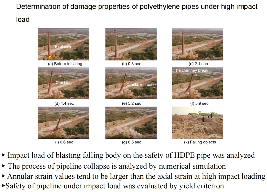
- Impact load of blasting falling body on the safety of HDPE pipe was analyzed
- The process of pipeline collapse is analyzed by numerical simulation
- Safety of pipeline under impact load was evaluated by yield criterion
- Annular strain values tend to be larger than the axial strain at high impact loading
1. Introduction
With the development of our country, it is becoming more and more important to protect the environment from pollution, and a large number of industrial chimneys have been abandoned. To save land resources, the abandoned chimneys were pulled down. The mechanical method and blasting are the two common ways for chimneys demolition. For taller chimneys, demolition by blasting will be safer and more efficient. But blasting demolition will bring a lot of negative effects, such as blasting flying stone, dust, noise, earthquake effect. Among them the biggest influence is the earthquake effect. Seismic effects are mainly composed of shock waves from explosions and vibration waves, which are generated when a building collapses and touches the ground. The city’s underground pipelines are intricate. High density polyethylene pipe (HDPE) pipes are widely used in municipal sewage transportation due to its good corrosion resistance, impact resistance, environmental protection and low cost. At present, the damage of urban pipelines is mainly caused by third-party reasons. Among them, the impact load generated by demolition blasting is larger in amplitude than that of urban subway tunnel blasting and deep foundation pit blasting vibration and natural earthquakes, and it is easier to damage the pipeline. If the ground impact load caused by the demolition of the chimney is too large, the pipeline will be ruptured and the sewage will leak, rendering inconvenience to residents and contaminate the surrounding soil. Therefore, it is of great practical engineering significance and scientific research value to study the dynamic characteristics of pipelines under the impact load caused by demolition and blasting of tall chimneys and evaluate the safety of pipelines.
At present, the research of domestic and foreign scholars in demolition blasting mainly focuses on the damage effect of explosive on the object itself. For example, Kazunori Fujikake [1] studied the residual resistance strength of reinforced concrete columns in buildings and the strength of reinforcing bars in the columns during demolition by blasting. Koji Uenishi [2] took blasting demolition of pier of a highway bridge as an example and verified the accuracy of the numerical model in simulating the change of mechanical properties of reinforcement in the process of blasting demolition by using field test data. Sun et al. [3] analyzed the obtained data by removing the cylinder in the 56 m high frame structure and proposed the concept of stress transient model that can be used for numerical simulation.
However, the seismic effect of the impact load caused by blasting demolition should be paid more attention to. The seismic effect is mainly composed of the shock wave caused by explosive explosion and the vibration wave caused by the falling object touching the ground, the latter being the main component. The mechanism of earthquake caused by blasting, vibration caused by ground collapse and natural earthquake damage to buildings (structures) is similar. This damage is caused by the sudden release of a large amount of energy and the propagation of elastic waves in the earth’s crust. But the frequency and energy amplitude between the three are different. Zhu et al. [4] proposed that the frequency of collapse impact load is between the frequency of blasting vibration (15-45 Hz) and the natural seismic frequency (2-5 Hz), which is generally 2-22 Hz. Zhong et al. [5] found that when the excitation frequency was 4 Hz-9 Hz, the peak strain of PE pipeline was the most obvious, suggesting that the natural vibration frequency of HDPE pipeline was less than 10 Hz. Therefore, the collapse impact load is more likely to cause the pipe resonance damage.
In terms of pipeline response characteristics under impact load, many scholars have studied pipeline response and failure characteristics under natural geological hazards by means of laboratory model test and numerical simulation [6-9]. Zhu et al. [10] has carried out 52 impact tests on seamless low-carbon steel pipe, and proposed the dynamic inelastic response and failure prediction of pipe under mass impact. Deng et al. [11] used discrete element software to simulate the dynamic response of buried pipelines caused by high-speed falling rock mass impacting the ground. It is proposed that the pipeline is more likely to undergo large deformation when the pipeline depth is increased and the non-sticky sand is filled. Yu et al. [12] proposed a numerical modal prediction method for pipeline deformation by simplifying the seabed soil into rigid bodies. Jiang et al. [13] applied finite element software to simulate the response characteristics of the pipeline under the impact load, and revealed the influence of various mechanisms on the response of the pipeline. According to this, these impact loads are mostly caused by natural geological disasters, such as landslide, collapse, debris flow and so on. These engineering geological disasters are mostly located far away from urban areas and most of the pipelines are steel pipes or cast-iron pipes. However, demolition blasting engineering are mostly concentrated in urban areas, and the pipeline types are complex. Therefore, it is of certain practical engineering value to study the impact load of blasting collapse on pipeline.
This paper mainly studies the dynamic performance of adjacent buried HDPE pipeline under the impact load of chimney demolition blasting. Firstly, the stress of pipeline under impact load is obtained by using Hertz collision formula and Boussinesq equation, and the peak surface vibration velocity is predicted (Section 3). Then, the data of maximum impact load, earth pressure and vibration velocity on the surface, as well as the vibration velocity and dynamic strain of the pipeline are processed. The propagation law of blasting impact load in demolition is analyzed, and the reliability of theoretical analysis results is verified by monitoring data (Section 4). Finally, the pipeline safety was evaluated with Von Mises yield criteria (Section 5).
2. Materials and methods
2.1. Theoretical solution of impact load and vibration velocity
Compared with the blasting vibration, the impact load generated by the blasting falling body has greater strength, longer duration and lower frequency, and it is more harmful to the protection target. Assuming that the soil is linear elastomer and the impact load of demolition blasting is considered as elastic collision, the Hertz collision theory can be used to obtain the maximum impact load under the action of the center of gravity. Combined with the theory of semi-infinite space elastomer, the Boussinesq equation is used to calculate the stress state formula of pipeline under impact load.
The impact load generated by blasting demolition body can be defined as the impact load generated by heavy weight falling from a height to touch the ground. The removed body and soil can be regarded as two elastic spheres and respectively. The impact load caused by falling weight m1 can be calculated by Hertz collision theory formula. The form is shown in Eq. (1) [14]:
where: – maximum surface impact load, MPa. , – the mass of two bounces, kg; – the instantaneous velocity before the collision, m/s; – constant. It can be obtained from the following Eq. (2-4):
where: , – the radius of the two bounces, m. , – the modulus of elasticity of the two bounces, MPa; , – the Poisson’s ratio of the two bounces.
Because the stiffness of the removed body is much greater than that of the soil, the soil is regarded as a semi-infinite elastic solid. Therefore, it can be regarded as → ∞, → ∞, → ∞ [15]. Therefore, Eqs. (2-4) can be expressed as:
2.2. Load analysis of pipeline
By using the semi-infinite space elastomer theory and the Boussinesq equations, the stress acting on the pipe in all directions can be calculated [16]. A schematic diagram of pipe pressure is shown in Fig. 1. The calculation formulas of tangential stress , axial stress and plane shear stress under the impact load are respectively shown in Eq. (7-9):
where: – the maximum load on the soil surface, MPa; – tangential stress of pipeline, MPa; – axial stress of pipeline, MPa; – shear stress of pipeline plane, MPa; – distance from the top of the pipe to the surface, m; – horizontal distance from tube top to operation point, m. – Poisson’s ratio of bounce 2 (soil mass).
Fig. 1Schematic diagram of pipeline stress under impact load
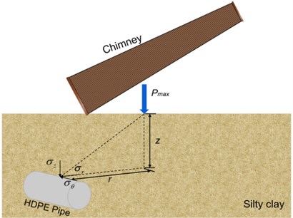
Under the high-speed impact load of a falling object, the vertical force on the pipeline is not only the impact load, but also the dead weight stress map of the upper soil. By using the semi-infinite space elastomer theory and Boussinesq equation, the vertical (or annular) stress acting on the pipeline by impactor can be calculated, as shown in Fig. 1. The radial stress at the pipe vertex under impact load is shown in f Eq. (10):
where: represents radial stress of pipeline under impact load, MPa; represents the maximum load on the soil surface, MPa; represents distance from the top of the pipe to the surface, m; represents horizontal distance from tube top to operation point, m.
The position of the water line shall be taken into account in the calculation of the earth pressure acting on the pipeline. In this project, the water level line is under the pipe, and the earth pressure applied on the pipe is a constant load generated by the weight of the soil. The radial stress of the pipeline under the action of earth pressure can be calculated as follows:
where: represents radial stress of pipeline under the action of overburden pressure, MPa; represents silty clay volumetric weight, MPa; represents distance from the top of the pipe to the surface, m.
Since the pipeline force is related to buried depth , combined with Eq. (10-11), the radial force received by the pipeline is shown in Eq. (12) [17]:
where: represents perforation coefficient, which is a coefficient related to the buried depth of pipeline. It can be evaluated as shown in Table 1.
Table 1Comparison of theoretical and measured data
Pipeline buried depth / m | 0-0.3 | 0.3-0.6 | 0.6-0.9 | >0.9 |
1.5 | 1.35 | 1.35 | 1.15 |
2.3. Surface vibration velocity
There is no unified formula to calculate the collapse vibration velocity caused by the collapse of a structure. At present, a researcher at the institute of mechanics, Chinese academy of sciences, is generally used for calculation [18]. According to the regression analysis of the measured vibration monitoring data of similar projects in Wuhan by Wuhan blasting company, 3.37 and 1.66 were calculated:
where: – collapse vibration velocity, cm/s; – mass of falling member, kg; – gravitational acceleration, m/s2; – height of gravity center of collapse, m; – failure strength of surface medium, MPa; – the distance from the measuring point to the center of the impact, m; , –attenuation parameter.
3. Demolition blasting test
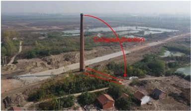
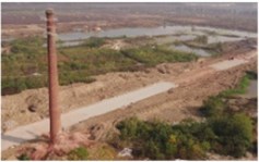
Currently, because of the many advantages of HDPE pipes, it is widely used in Wuhan urban water supply and drainage systems. The demolition blasting project is located near the brick and tile village of No. 1 team, Xingou Town, Dongxihu District, Wuhan City. Due to urban road reconstruction, a 50 m high brick chimney needs to be demolished. The surrounding environment of the demolished object is relatively simple, as shown in Fig. 2. The east side of the chimney is 218 meters from the house; The south side is open, with no building within 200 meters. The west side of the chimney is 53 meters from the house. Therefore, in order to achieve the purpose of safety and efficiency, it can be demolished by blasting.
Fig. 2Aerial view of the surrounding environment
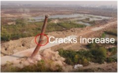
The specific collapse process of chimney demolition and blasting is shown in Fig. 3. According to Fig. 3, dust from the inner wall of the chimney began to fly out from the mouth of the chimney after the detonation of 0.3 seconds. After detonation for 2.1 seconds, the chimney became unstable and began to collapse due to the destruction of the center of gravity. At 4.4 seconds, the chimney continued to collapse and cracks appeared in the middle. When the chimney breaks in 5.2 seconds, the crack gradually increases and continues to collapse. The chimney broke into two parts in 5.9 seconds. After 6.6s, the lower part of the chimney continued to collapse, and the upper part shifted to the bottom of the chimney due to inertia. The chimney collapsed at 8.5 seconds. The demolition blasting lasted 8.5 seconds. The removal of waste materials is shown in Fig. 3(k).
3.1. Test parameters
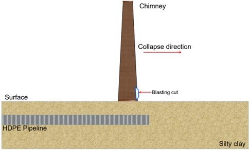
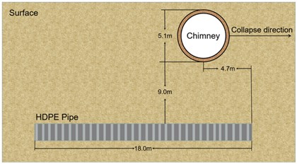
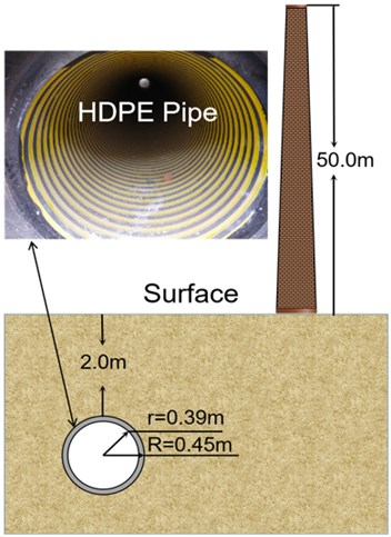
The blasting chimney is a brick structure. The total height of the chimney is 50 m. The outer radius of the bottom is 2.55 m, the inner radius is 1.5 m, and the wall thickness is 1.05 m. Chimney density 1600 kg·m-3, collapse mass 7×10⁵ kg, collapse height 20 m. Next to the chimney is an HDPE sewage pipe buried in the ground. The soil layer embedded in the pipe is a typical silty clay layer of Wuhan stratum, with a depth of 2 m. The vertical distance between the chimney and the pipeline axis is 9 m. The direction of the chimney collapse is parallel to the direction of the pipeline axis. The outside diameter is 90 cm and the inside diameter is 78 cm. The total length of the pipeline is 18 m, and the length of each of the three sections is 6 m. The pipe interface is socket type, and the thickness of rubber ring at the pipe interface is 0.5 cm. The spatial position relationship between pipe and chimney is shown in Fig. 4. The dimensions of pipes and chimneys are shown in Fig. 5.
Fig. 3Demolish collapse flow
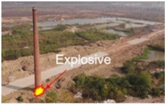
a) Before initiating
b) 0.3 sec

c) 2.1 sec

d) 4.4 sec
e) 5.2 sec

f) 5.9 sec

g) 6.6 sec

g) 8.5 sec

k) Falling objects
Fig. 4Schematic diagram of the relationship between pipe and chimney position
The temperature in the pipe is 20 ℃. The environment temperature in the pipe is 20 ℃. Pipeline physical parameters: Poisson’s ratio 0.46; density 936 kg·m-3, Young’s modulus 834.9 MPa, ring stiffness 8kN·m-2, strength limit 31.6 MPa, elongation 116 %.
Because the chimney adopts the directional collapse scheme and the collapse distance is allowed, the blasting cut is arranged at the bottom of the chimney. The incision shape was positive trapezoid, the central angle of the incision was 216°, and the incision height was 1.5 m. The 2# rock emulsion explosive is adopted, the hole diameter is 40 mm, the depth is 70 cm, the spacing is 50 cm, the row spacing is 50 cm. The single hole charge is 300 g.
Fig. 5Chimney and pipe size and space position, a) planform, b) sectional view
a)
b)
3.2. Monitoring scheme and arrangement of measuring points
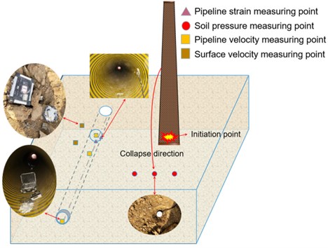
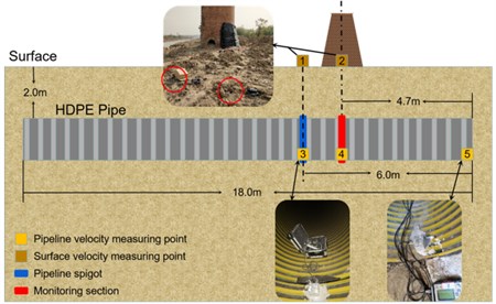
The purpose of this experiment is to obtain the change of earth pressure, the change of velocity of the pipe and the soil above the pipe, and the change law of dynamic strain of the pipe under the impact load caused by demolition blasting and collapse of the chimney. For the purposes mentioned above, the main test items include: pipeline dynamic strain (), pipeline particle vibration velocity () and earth pressure (), and particle velocity above the pipeline (). The point space diagram of each monitoring item is shown in Fig. 6.
Fig. 6Schematic diagram of monitoring points
3.2.1. Soil pressure
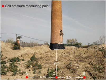
In order to study the change characteristics of earth pressure caused by the collapse of chimney demolition to the ground, three earth pressure boxes were embedded under the center of gravity of the collapsed object. Three earth pressure boxes were buried at equal distances, with a spacing of 2.5 m. The middle earthen box is at the center of the chimney collapse. The line of the earth pressure cells is perpendicular to the established collapse axis, and the line is 20 m away from the chimney. The buried earth pressure box is shown in Fig. 7. The whole bridge of the earth pressure box is connected, and DH5956 dynamic signal acquisition instrument is used for data acquisition.
Fig. 7Soil pressure test point
3.2.2. Dynamic strain
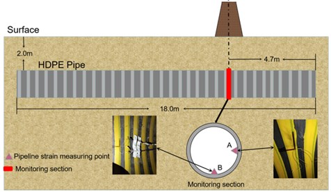
In order to study the stress and strain state of pipeline under blasting vibration, a monitoring section is set in the numerical model. The monitoring section is located at the shortest distance from the chimney, 4.7 m from the pipe ends. Two measuring points are arranged along the annular direction of the pipeline, and the annular strain gauge and axial strain gauge were arranged at each measuring point. There were 4 strain gauges in total. As shown in Fig. 8. The strain gauge with length of 80 mm and resistance 120 Ω is instrumented on the pipeline and connected with a quarter of the bridge to DH5956 with a measuring accuracy of 10 microstrain and sampling rate 20000 Hz/channel.
Fig. 8Dynamic strain test point
3.2.3. Vibration velocity
In order to study the vibration velocity change of the particle, including particles on the surface and in the pipeline. The tc-4850 blasting vibration meter was selected as the vibration velocity measurement system. Due to the influence of soft soil properties on vibration propagation and monitoring, a special support device is used to fix the sensor o TC-4850, as is shown in Fig. 7. The device can connect vibration sensors to soil particles, and the sensor will not be loose and unable to collect data during the process of vibration wave propagation.
Three vibration velocity measuring points are arranged in the pipeline, which are located at the pipe end (measuring point 5) inside the pipeline, the closest position to the center of the chimney axis (measuring point 4) and the pipe joint interface (measuring point 3). Two measuring points are placed on the surface above the pipeline, namely, ground measurement point 1 is directly above measurement point 3, and ground measurement point 2 is directly above measurement point 4. All points are shown in Fig. 9. Because there is a sewage well at the position of the pipe opening, the vibration velocity measuring point is not arranged on the ground directly above the pipe opening.
Fig. 9Vibration velocity test point
4. Analysis of test results
4.1. Soil pressure
Combined with the principle of soil pressure test, the soil pressure measured in the test is the product of the strain of the soil pressure box and the constant coefficient , the unit is MPa. Therefore, the earth pressure curve obtained by data processing is shown in Fig. 10.
Fig. 10Soil pressure test results
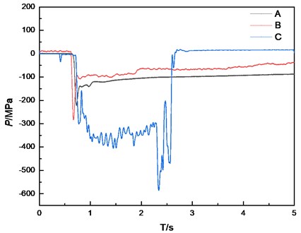
It can be known that the impact load at the center of gravity of chimney collapse is the largest, with a value of 590.3 MPa. There is little difference in the peak value of impact load on both sides, and its value is smaller than the center of the pipeline. All monitoring points are subjected to compressive stress. According to curve C, the acting time of impact load is about 2 seconds and reaches its peak value when it is close to 2.5 seconds. However, curve AB shows that at the chimney edge, the impact load is a three-stage change law, which first reaches the peak value and then gradually decreases and finally tends to equilibrium.
4.2. Dynamic strain
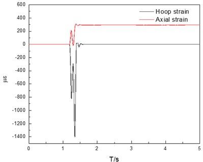
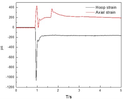
Due to the low frequency and long duration of impact load, the collected data need to be de-noised. The dynamic strain of each measurement point of the pipeline after denoising is shown in Fig. 11. According to the results shown in the Fig. 11, the point dynamic strain at A above the pipeline is smaller than that at B on the explosion-facing side of the pipeline, and the annular strain at both points is larger than the axial strain. Annular is compressive strain, axial is tensile strain. The maximum microstrain of the circumferential strain at point A is 1403, and the maximum microstrain of the circumferential strain at point B is 1065. Due to the propagation characteristics of caving impact load, its propagation law under the surface is similar to blasting seismic wave, both of which are dominated by P wave incidence. Combined with the practical engineering situation, the vibration shock wave first propagates to the explosion-facing side of the pipeline, and the effect on the top of the pipeline is relatively weak.
Fig. 11Dynamic strain test results, a) measuring point A, b) measuring point B
4.3. Vibration velocity
As a reflection of the energy when the blasting seismic wave passes through the medium, the vibration velocity is the most intuitive measurement data in vibration monitoring. According to the experimental protocol mentioned above, the monitoring data of collapse vibration velocity of demolition blasting is obtained. The vibration velocity and dominate frequency of each direction of the 5 measuring points are listed as shown in Table 2. According to the statistical results in the table, it can be seen that: 1) The internal vibration velocity of the pipeline is greater than the surface vibration velocity; 2) Main frequencies in all directions are concentrated between 5 Hz-20 Hz; 3) The vibration velocity and dominate frequency of the particle in the direction in the pipeline are greater than and direction, while the vibration velocity of the particle in the direction at the surface is smaller than and and the frequency is greater than and . This is because the impact vibration wave operating point is located at the surface, so the surface is easier to be affected by the surface wave, so the horizontal direction of the vibration speed is greater than the vertical direction. However, the shock vibration wave propagates the body wave in the soil, so the particle vibration velocity has more influence in the vertical direction.
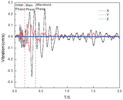
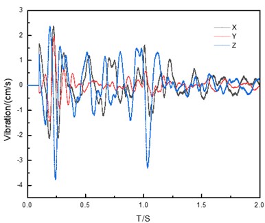
The vibration velocity waveforms of surface measurement point 1 and pipeline measurement point 4 are shown in Fig. 12(a) and 12(b). The vibration shock wave generally consists of three stages in the propagation process, namely the initial phase, the main phase and the aftershock phase. Combined with Fig. 12(a), it can be seen that the collected data of vibration shock wave conforms to the theory.
Table 2Statistics of vibration velocity results
Measuring point | / (cm/s) | / Hz | / (cm/s) | / Hz | / (cm/s) | / Hz | / (cm/s) |
1 | 0.353 | 10.336 | 0.13 | 11.142 | 0.008 | 17.937 | 0.377 |
2 | 0.143 | 6.768 | 0.05 | 6.079 | 0.007 | 16 | 0.152 |
3 | 2.26 | 8.163 | 0.829 | 13.937 | 3.365 | 40.816 | 4.137 |
4 | 2.367 | 12.8 | 1.967 | 10.695 | 3.762 | 11.364 | 4.860 |
5 | 1.77 | 5.743 | 1.935 | 5.682 | 4.215 | 6.873 | 4.964 |
Fig. 12Vibration velocity results, a) measuring point 1, b) measuring point 4
4.4. Validation for theoretical analysis by example and numerical simulation
The data of the project case is put into the theoretical calculation formula mentioned above. This is equivalent to a sphere with a radius () of 4.71m, depending on the mass and density of the chimney. The initial velocity of the ball () at the moment of free fall is 98 m/s. The elastic modulus () of silty clay is 5 MPa.
According to Eq. (6), the maximum impact load generated by this project is 684.3 MPa. Combined with the pipeline stress state Eq. (7-12), the different stresses on the pipeline can be obtained, as shown in Table 3. According to the surface vibration velocity prediction formula, the combined vibration velocity at the actual surface monitoring point 1 and 2 can be calculated as 0.451 cm/s and 0.178 cm/s, respectively.
Table 3List of stresses
Type of stress | Tangential stress | Axial stress | Radial stress | Shear stress |
Value / MPa | 0.022 | 0.052 | 0.61 | 0.0002 |
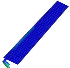
The process of numerical simulation is as follows. Firstly, the numerical model of pipeline collapse is adopted to obtain the pressure of pipeline collapse to the ground. Secondly, the surface pressure is obtained according to the location of pipeline collapse, and the pressure is applied to the pipeline model for calculation. The specific numerical model parameters are shown as follows.
The pipe is high-density polyethylene, and it is a viscous-elastic material. This material can be modeled by *MAT_ PLASTICITY_POLYMER. This is an elastic-plastic material model that can define an arbitrary stress-strain curve and arbitrary strain rate dependency. Furthermore, the model can simulate the exact brittle response of the polymer at high strain. The stress-strain curve used in this study is obtained by [19]. The equation can be expressed as:
The physical and mechanical parameters are determined by experiments, other parameters in the equation are determined by Reference and shown in Table 4.
Table 4Parameters in Kwon constitutive equation
0.015 | –22.29 | 33.41 | 0.0149 | 0.001 | 15.50 |
35.517 | 0.077 | 0.32 | 30.66 | 0.4953 | 1.80 |
The calculation parameters used in the numerical simulation are based on laboratory mechanical tests. All materials in the model are simplified to be isotropic and homogeneous without considering the material fracture, rock mass joints, and discontinuities. *MAT_DRUCKER_PRAGER is used to model the silty clay [20]. The frictional angle and cohesion determine the yield surface. The modified Drucker-Prager yield surface is used in this material model enabling the shape of the surface to be distorted into a more realistic definition for soils. The yield surface is expressed as:
where is the shear strength, is the mean stress, is the internal friction angle, is the cohesion.
*MAT_PLASTIC_KINEMATIC material model is used for strong weathered sandstone and stemming. To manage the material failure, the PK material model is used in conjunction with the secondary created material failure criterion model *MAT_ADD_EROSION of LS-DYNA. The constitutive formula is as follows:
where is the yield stress, is the initial yield stress, and are the strain rate parameters, is the strain rate, is the effective plastic strain, is the plastic hardening modulus, is the hardening coefficient:
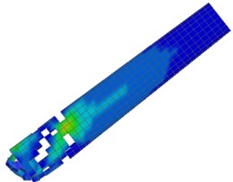
where is the tangent modulus and is Young’s modulus. The physical and mechanical parameters of soil, rock, and stemming are shown in Table 5. The numerical simulation process of chimney collapse is shown in Fig. 13.
Table 5Physical and mechanical parameters
Material | Density / g·m-3 | Elastic modulus / GPa | Shear modulus / GPa | Poisson’s ratio | Cohesion / MPa | Internal friction angle/° | Tensile strength / MPa |
HDPE pipe | 0.941 | 0.758 | 0.26 | 0.40 | – | – | 31.6 |
Silty clay | 1.98 | 0.11 | 0.044 | 0.33 | 0.035 | 15 | 0.028 |
Chimney | 1.8 | 12 | – | 0.15 | – | – | 1.5 |
Fig. 13Numerical simulation process of chimney collapse

a) 0 sec

b) 4.4 sec
c) 5.2 sec
d) 6 sec
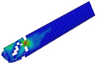
e) 6.6 sec
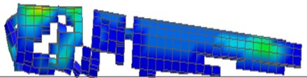
f) Falling objects
The maximum impact load and surface combined vibration velocity obtained by theoretical calculation are compared with the actual engineering test results and numerical simulation results, as shown in Table 6. It can be found that the value obtained by theoretical calculation is slightly larger than the actual monitoring data. The reason is that the discontinuity of soil during the propagation of shock wave is not considered in the theoretical calculation, which results in energy loss. So the vibration amplitude is reduced. And in the actual blasting process, the chimney collapse form is not the whole collapse. Therefore, theoretical calculation is larger than actual monitoring data. However, the error between them is less than 20 %, so the theoretical results are reliable.
It needs to be explained that: a. Combined with the actual situation, the amplitude of impact load decreases rapidly with the increase of horizontal distance from the pipe, and the frequency also decreases with the increase of distance from the action center of impact load. Therefore, the probability of failure due to resonance in the far zone is small. b. In the near region, the shock load frequency is similar to the natural vibration frequency of the pipeline, so when the amplitude of energy reaches the strength limit of the pipeline, the pipeline is easy to be destroyed. Therefore, the impact load calculated by Eq. (6-12) is reasonable. 3. It is assumed that the ground plane of the project chimney collapse is a horizontal semi-infinite space elastomer.
Table 6Comparison of theoretical and measured data
Type of dynamic response parameter | Theoretical calculation | Actual monitoring | Error / % | Theoretical calculation | Numerical simulation | Error / % |
/ (cm/s) | 0.451 | 0.377 | 19.6 | 0.451 | 0.41 | 9.09 |
/ (cm/s) | 0.178 | 0.152 | 17.1 | 0.178 | 0.172 | 3.37 |
/ MPa | 684.8 | 590.3 | 16.0 | 684.8 | 659 | 3.76 |
5. Assessment of pipeline safety
Since it is not convenient to monitor the pipeline directly in the actual project, the vibration velocity can only be monitored on the surface. Combined with the above monitoring data, it can be seen that the vibration velocity of the pipeline is much higher than that of the ground. Therefore, before the actual project starts, the safety of the pipeline needs to be evaluated. If the critical value of the pipeline strength is reached, the damping facilities should be added in time to ensure the safety of the pipeline around the project.
The HDPE pipe monitored by blasting demolition test has good impact resistance. Since the pipeline under impact load is more likely to be damaged in the annular direction, the maximum allowable circumferential strain of the pipeline can be determined according to rule 4.4.6 [21]. That is, under the combined action of polyethylene pipe, the calculation of the maximum vertical deformation should meet the following conditions:
where: is the maximum vertical deformation of polyethylene pipe under the combined action; is the calculated diameter of the pipe.
Then, the maximum allowable annular compression and tensile strain are both 5 %.
Compared with other material pipeline, it is obvious that the permissible strain of HDPE pipeline is bigger than others. As mentioned above, the strength limit of the pipeline is only 31.6 MPa, that is, when the pipeline reaches the maximum allowable strain, the stress has exceeded the strength limit, so it is unreasonable to judge the safety state of the pipeline by the strain alone. Considering that the failure mode of HDPE pipe is yield failure, the failure behavior of HDPE pipe is determined by the Von Mises yield criterion. According to the Mises yield criterion, Mises equivalent stress shall not exceed yield stress , as shown in Eq. (15) [22]:
where: is Mises equivalent stress, is the first principal stress, is the second principal stress, is the third principal stress, is the yield stress.
The relationship between yield stress and strain rate of HDPE pipe satisfies the Eyring equation [23], that is, the relationship between yield stress and logarithmic strain rate satisfies the following equation:
where: is the strain rate.
The annular strain and axial strain at strain measuring point 2 were differentiated once to obtain the strain rate of the pipeline. The maximum strain rate is 0.04 s, and the yield stress 26.18 mPa is obtained by applying Eq. (16).
According to the values of the three stresses and shear stresses on the top of the pipe calculated above, the shear stress is much smaller than the stress in the three directions. Therefore, it can be considered that the first principal stress at the top of the pipe is radial stress , the second principal stress is axial stress , and the third principal stress is tangential stress . The equivalent stress is 0.51 MPa. The yield stress of HDPE pipe is much less than that of HDPE pipe, so the pipe under impact load generated by demolition blasting engineering is safe.
It needs to be explained that: a) The calculation assumes that the soil is linearly elastic and homogeneous, and there is no relative slip of the pipe soil under the action of blasting seismic waves. The pipeline material is nonlinear viscoelastic and satisfies isotropy; b) The calculation object is the pipe location of the directly buried pipeline, without considering the interface, bend and so on. According to the requirements of the specification, the weak links such as interface and bend are processed by means of flange, sleeve and hot melt, so that the strength is greater than that of the pipe body. Therefore, it is reasonable to take the tube body as the research subject to calculate its control vibration velocity.
6. Conclusions
Through field monitoring of demolition blasting engineering and theoretical analysis and numerical simulation, the influence of vibration load on HDPE bellows is studied. The main conclusions are as follows:
1) The impact load frequency of collapse vibration ranges from 5 Hz to 20 Hz, which is between the natural earthquake and the blasting vibration frequency. The surface vibration velocity above the pipeline is much lower than the surface vibration velocity inside the pipeline, and the surface vibration velocity waveform consists of obvious initial vibration phase, main vibration phase and residual vibration phase.
2) The vibration shock wave mainly propagates in the form of surface wave and in the form of body wave under the surface. The strain on the blasting side of pipeline is greater than that on the top of pipeline.
3) The maximum impact load obtained by theoretical calculation is close to the actual vibration velocity on the surface of the pipeline, and the dynamic response calculation of the pipeline based on the theory is basically reliable.
4) Combined with Von Mises yield criteria, it is safe to dismantle pipelines under blast impact load. At the same time, the method proposed in this paper is based on the Theory of Semi-infinite space Elastomer, which has certain limitations in the stochastic calculation of the load form. If the load form can be extended to the actual random wave model, the reliability of the obtained data will be clearer.
References
-
K. Fujikake and P. Aemlaor, “Damage of reinforced concrete columns under demolition blasting,” Engineering Structures, Vol. 55, pp. 116–125, Oct. 2013, https://doi.org/10.1016/j.engstruct.2011.08.038
-
K. Uenishi, H. Takahashi, H. Yamachi, and S. Sakurai, “PC-based simulations of blasting demolition of RC structures,” Construction and Building Materials, Vol. 24, No. 12, pp. 2401–2410, Dec. 2010, https://doi.org/10.1016/j.conbuildmat.2010.03.002
-
J. Sun, Y. Jia, Y. Yao, and X. Xie, “Experimental investigation of stress transients of blasted RC columns in the blasting demolition of buildings,” Engineering Structures, Vol. 210, p. 110417, May 2020, https://doi.org/10.1016/j.engstruct.2020.110417
-
B. Zhu, N. Jiang, C. Zhou, X. Luo, Y. Yao, and T. Wu, “Dynamic failure behavior of buried cast iron gas pipeline with local external corrosion subjected to blasting vibration,” Journal of Natural Gas Science and Engineering, Vol. 88, p. 103803, Apr. 2021, https://doi.org/10.1016/j.jngse.2021.103803
-
Zhong, Gong, Han, and Li, “Monitoring the dynamic response of a buried polyethylene pipe to a blast wave: an experimental study,” Applied Sciences, Vol. 9, No. 8, p. 1663, Apr. 2019, https://doi.org/10.3390/app9081663
-
N. Jiang et al., “Safety criterion of gas pipeline buried in corrosive saturated soft soil subjected to blasting vibration in a coastal metro line,” Thin-Walled Structures, Vol. 180, p. 109860, Nov. 2022, https://doi.org/10.1016/j.tws.2022.109860
-
S. K. Ghosh, W. Johnson, S. R. Reid, and T. X. Yu, “On thin rings and short tubes subjected to centrally opposed concentrated loads,” International Journal of Mechanical Sciences, Vol. 23, No. 4, pp. 183–194, Jan. 1981, https://doi.org/10.1016/0020-7403(81)90044-8
-
T. Wu, N. Jiang, C. Zhou, X. Luo, H. Li, and X. Chang, “An innovative test equipment with rate-dependence in interface damage and its operation under cyclic loading,” Review of Scientific Instruments, Vol. 92, No. 8, p. 085104, Aug. 2021, https://doi.org/10.1063/5.0056150
-
M. Saber, D. W. J. Tanner, W. Sun, and T. H. Hyde, “Determination of creep and damage properties for P92 at 675 °C,” The Journal of Strain Analysis for Engineering Design, Vol. 46, No. 8, pp. 842–851, Nov. 2011, https://doi.org/10.1177/0309324711413012
-
C. S. Ng and W. Q. Shen, “Effect of lateral impact loads on failure of pressurized pipelines supported by foundation,” Proceedings of the Institution of Mechanical Engineers, Part E: Journal of Process Mechanical Engineering, Vol. 220, No. 4, pp. 193–206, Nov. 2006, https://doi.org/10.1243/0954408jpme97
-
X. J. Deng, S. F. Xue, and X. H. Tong, “Numerical simulation on response of buried pipeline induced by rock-fall transverse impaction,” Journal of China University of Petroleum (Edition of Natural Science), Vol. 33, No. 6, pp. 111–115, 2009.
-
J.-X. Yu, Y.-Y. Zhao, T.-Y. Li, and Y. Yu, “A three-dimensional numerical method to study pipeline deformations due to transverse impacts from dropped anchors,” Thin-Walled Structures, Vol. 103, pp. 22–32, Jun. 2016, https://doi.org/10.1016/j.tws.2016.02.006
-
F. Jiang, S. Dong, Y. Zhao, Z. Xie, and C. Guedes Soares, “Investigation on the deformation response of submarine pipelines subjected to impact loads by dropped objects,” Ocean Engineering, Vol. 194, p. 106638, Dec. 2019, https://doi.org/10.1016/j.oceaneng.2019.106638
-
D. Gugan, “Inelastic collision and the Hertz theory of impact,” American Journal of Physics, Vol. 68, No. 10, pp. 920–924, Oct. 2000, https://doi.org/10.1119/1.1285850
-
M. Liu and M. Yang, “Modeling the behavior of natural gas pipeline impacted by falling objects,” Engineering Failure Analysis, Vol. 42, pp. 45–59, Jul. 2014, https://doi.org/10.1016/j.engfailanal.2014.03.008
-
P. A. Clarkson and M. D. Kruskal, “New similarity reductions of the Boussinesq equation,” Journal of Mathematical Physics, Vol. 30, No. 10, pp. 2201–2213, Oct. 1989, https://doi.org/10.1063/1.528613
-
“Guidelines for the design of buried steel pipeline,” USA, The American Society of Civil Engineers, 2005.
-
D. Z. Liu, Practical Manual of Engineering Blasting. Beijing: Metallurgical Industry Press, 1999.
-
R. T. Moura, A. H. Clausen, E. Fagerholt, M. Alves, and M. Langseth, “Impact on HDPE and PVC plates – Experimental tests and numerical simulations,” International Journal of Impact Engineering, Vol. 37, No. 6, pp. 580–598, Jun. 2010, https://doi.org/10.1016/j.ijimpeng.2009.12.004
-
G. Oettl, R. F. Stark, and G. Hofstetter, “A comparison of elastic-plastic soil models for 2D FE analyses of tunnelling,” Computers and Geotechnics, Vol. 23, No. 1-2, pp. 19–38, Jul. 1998, https://doi.org/10.1016/s0266-352x(98)00015-9
-
“Technical specification for outdoor buried polyethylene (PE) water supply pipeline engineering,” DBJ52T 039-2017, 2017.
-
X. Luo, S. Lu, J. Shi, X. Li, and J. Zheng, “Numerical simulation of strength failure of buried polyethylene pipe under foundation settlement,” Engineering Failure Analysis, Vol. 48, pp. 144–152, Feb. 2015, https://doi.org/10.1016/j.engfailanal.2014.11.014
-
P. S. He, Mechanical Properties of Polymers. Hefei: Press of University Science and Technology of China, 2008.
About this article

The study was sponsored by the Hubei Key Laboratory of Blasting Engineering Foundation (Grant No. HKLBEF202001) and the National Natural Science Foundation of China (Grant No. 41807265 and Grant No. 41972286), and Natural Science Foundation of Hubei Province (2021CFB541).
